Korea Aerospace Research Institute (KARI) is performing pre-phase development of a lunar explorer which is targeted to be launched in early next decade. This preparation includes development of a simulator to be used in the design of mission, in the development of key technologies such as guidance, navigation, and control (GNC)during lunar transfer, lunar orbit and lunar landing.
Simulator in the space program provides virtual environment that space vehicle is expected to confront during the mission period but hard to realize in the ground.For the lunar landing mission, lunar surface environment should be added to test safe landing performance. Landing algorithm especially for GNC and related hardware components can be tested rigorously using the simulator.
The following chapters describe simulator development objectives and requirements, simulator architecture,and trade study results for selecting simulator components. Characteristics of currently available lunar digital elevation maps (DEM) for lunar terrain regeneration are also summarized.
2. REQUIREMENTS FOR SIMULATOR DEVELOPMENT
Different kinds of simulators are used in each spacecraft development phase depending on required functions of the simulation. In the case of COMS program which is a geostationary satellite for communication,ocean and meteorology, KARI used functional validation bench for attitude and orbit control system validation,software test bench for compatibility test between data handling system and flight software, and dynamic satellite simulator system for validation of satellite operation (Lee et al. 2007, Koo et al. 2009).
KARI is developing a simulator for the lunar exploring mission. Primary objectives of developing simulator to be developed are 1) to analyze dynamic behavior of explorer in lunar orbit or in landing environment, 2) to verify GNC algorithm, and 3) to provide test environment for the technology development of vision-based lunar landing. Vision-based landing technology includes autonomous decision of landing site, hazard detection and avoidance during landing phase.
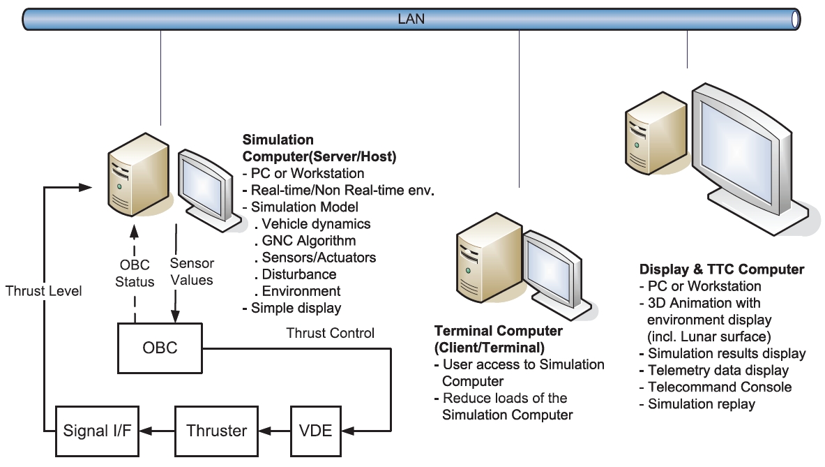
To derive requirements for developing simulator, possible use cases of the simulator are considered and they are software based simulation, processor in the loop simulation (PILS) / hardware in the loop simulation (HILS), and supporting ground-based flight test. Fig. 1 shows an example of PILS/HILS configuration among the use cases. Simulator consists of three computers: simulation computer, remote terminal computer, and display and telemetry, telecommand (TTC) computer. Simulation computer solves dynamic equations of models. Execution mode of the simulation computer can be either real-time or non real-time. Interfaces with the hardware in the simulation loop are also provided in that computer. User can access simulator from the remote terminal computer as well as from the simulation server. Three-dimensional (3D)-graphics requires much computational resources
thus 3D-graphics is processed in separate display and TTC computer. Each computer communicates through the Ethernet.
Like other space programs, lunar explorer development program is expected to be a long time project. Simulator needs to be improved during the project period with matureness of explorer design. Following concepts are considered as baseline for the simulator to be a useful tool during the whole lunar exploring mission:
3. SIMULATOR ARCHITECTURE DESIGN
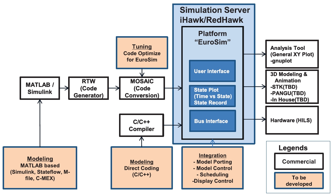
Simulator architecture suggested in this paper is shown in Fig. 2. A simulation platform, EuroSim, is located in the middle of the architecture. Model based modeling program, MATLAB/Simulink, is used for initial model generation. Models generated in MATLAB/Simulink are translated into C/C++ codes using the Real-Time Workshop (RTW). These codes are transformed to codes that can be used in EuroSim by using program MOSAIC, model-oriented software automatic interface converter. User can also generate models directly in the EuroSim environment using C/C++ programming language.
EuroSim provides basic plot functions for simulation result analysis. Additional plot function can be provided using the gnuplot program. Software for 3D-graphics representation of the simulation results and terrain display will be implemented on a separated computer.
European Space Agency (ESA) defined simulation standards simulation model portability (SMP) 1 and SMP2 to overcome the problem of model incompatibility between different simulators used for space programs (ESA 2002, European Space Operations Centre 2005). Platform in a simulator provides framework for simulation. There are several simulation platforms available and some of them support SMP1 and SMP2 standards. EuroSim, SIMSAT, SimVis, Basiles are simulator platforms that support SMP.
Among these platforms, EuroSim and SIMSAT are considered as candidates for the simulator under development.
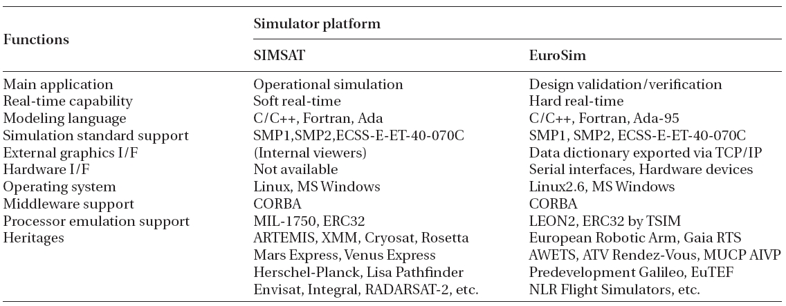
Table 1 shows summary of comparison between EuroSim and SIMSAT about the functions necessary in developing a simulator (Lee 2008). Comparison shows SIMSAT has merits of full support for SMP2 standard and has good features for operational simulator whereas EuroSim has merits of real-time support and external hardware interfaces. EuroSim has some limitations in supporting SMP2 but has advantage of supporting hard real-time, and supporting interface with various hardware such as MIL-1553, RS-422/232, etc. (DutchSpace 2008). Real-time performance of EuroSim partially depends on the specification of computer hardware and operating system but it is described that follows can be achieved on the EuroSim: maximum scheduler frequency of 1,000 Hz, maximum clock jitter less than 50 μsec, maximum interrupt latency less than 200 μsec (Vries 2006). Considering the objectives of developed simulator, EuroSim was selected as simulation platform.
One of the most important processes in implementing a simulator is modeling of vehicle and environments. Vehicle model includes spacecraft dynamics, actuator and sensor models. A simulator needs to provide tools for
[Table1.] Comparison of simulator platforms (Lee 2008).

Comparison of simulator platforms (Lee 2008).
generating model and ways for integrating these models into the simulator platform. In this research, widely used model based analysis tool, MATLAB/Simulink, is selected as a modeling tool.
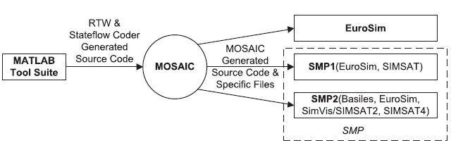
Model developed under MATLAB/Simulink can be translated into C/C++ codes by using RTW. But these codes cannot be used directly in the EuroSim. MOSAIC program is used for automatic code conversion into the form that can be used in the EuroSim. MOSAIC also provides code conversion to SMP1 or SMP2 compatible format. Automatic code conversion can eliminate errors that can be introduced by manual translation. Fig. 3 shows role of MOSAIC in the code conversion.
This approach enables spacecraft engineer to work with MATLAB/Simulink during the algorithm development, and to convert developed models later into codes that can be used in the simulation platform when real-time or PILS/HILS test is necessary.
Plot of simulation results can be initiated by pressing TestAnalyzer button on the EuroSim graphic user interface. Most of the necessary plots can be obtained from intrinsic plot functions. If more plot functions are needed, user can access various functions of gnuplot program through the command window of EuroSim.
Three dimensional-graphic expression of the simulation results can help understanding position or attitude of spacecraft. In case of lunar orbital mission, necessary 3D-graphics function will be almost the same with that of earth centered satellite case except central body is the moon instead of the earth. However, in case of lunar landing mission, regeneration of lunar terrain and visualization of the motion of the lander relative to that terrain are very important. Therefore 3D-graphics module in the developed simulator should have capability of 3D-graphics of general satellite and capability of generating 3D lunar surface based on real altitude data of the moon.
Method of implementing 3D-graphics function in the simulator is not fixed yet. But it is considered that developed 3D-graphics module will be used to display landing scenarios and to analyze landing performance of the explorer. We expect that the simulator will be applied for testing GNC algorithm in autonomous and soft landing. The simulator can also be used for developing or testing hardware for safe, hazard detection and avoidance during the landing.
Terrain of the moon can be generated in the simulator using DEM data which is obtained from previous lunar exploring programs. There are several published DEMs but SELENE DEM from Japan Aerospace Exploration Agency (JAXA) and Lunar Reconnaissance Orbiter (LRO) DEM from National Aeronautics and Space Administration (NASA) provide most high resolution data.
SELENE DEM is based on the results of Laser ALTimeter (LALT) measurement of SELENE mission. It provides lunar surface altitude data of 16 pixel/deg in both longitude and latitude direction for lunar global. For the area near the north and south poles which is most interesting
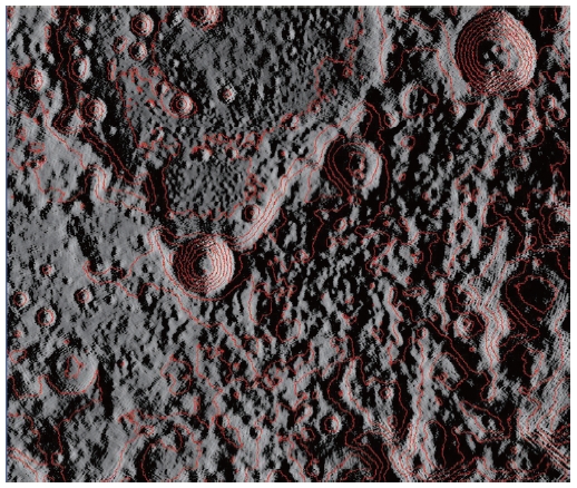
area for next lunar landing missions regardless of lunar exploration programs, higher resolution data is available. For the area above latitude of 80° in both north and south hemisphere, DEM data resolution of 30 pixel/deg, 128 pixel/deg are available in longitude and latitude direction, respectively. Fig. 4 shows lunar surface near north pole using SELENE data, LALT_GT_NP_IMG.IMG, with aid of program Jim’s Lunar Terminator Visualization Tool. Zoom factor of 30 is used and contour represents altitude with interval of 500 m.
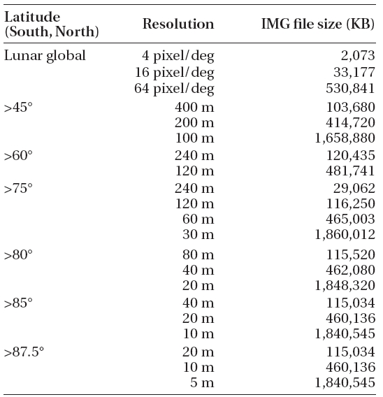
LRO DEM data is based on the results of Lunar Orbiter Laser Altimeter (LOLA) measurement of LRO mission. LRO data is being processed and it is announced that data will be updated every three months through NASA Planetary Data System (PDS). Resolution of LRO DEM for lunar global is 64 pixel/deg which corresponds to 0.47375 km/pixel. For the north and south pole area above 87.5° latitude, resolution of altitude data is 5 m/pixel. Table 2 shows available resolutions of DEM from LRO LOLA with lunar latitude.
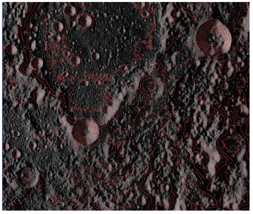
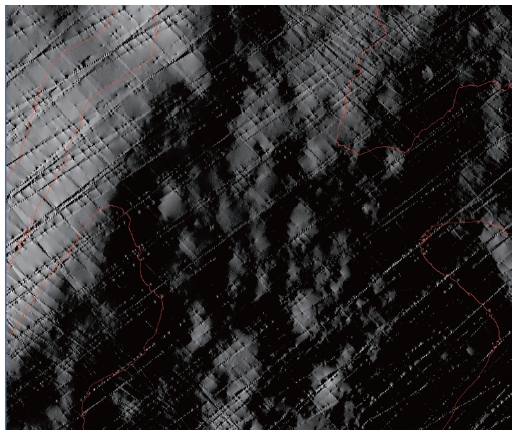
Fig. 5 shows lunar surface near north pole using LRO LOLA data IDEM_875N_5M.IMG. Zoom factor of 30 is used and contour represents altitude with interval of 500 m which is the same condition with Fig. 4. When compared with SELENE DEM data, terrain image generated by using LRO LOLA DEM contains more shapes, which implies more detailed surface shape. Because LRO LOLA data provides 5 m/pixel data on the pole area, terrain image can be magnified more. Fig. 6 is obtained by increasing zoom factor to 300 which is ten times magnified
[Table 2.] LRO LOLA DEM data resolutions with lunar latitude.

LRO LOLA DEM data resolutions with lunar latitude.
image from Figs. 4 and 5. In Fig. 6, some artifactitious shapes of terrain are observed. These shapes are related with different measurements in each observation track. It implies there is restriction in using high resolution LOLA DEM data directly and implies additional data processing is necessary to remove artifactitious shapes for using high resolution LOLA DEM data.
In this paper, top level requirements for simulator development that will be used for lunar explorer development including orbiter and lander is derived from the possible use cases of the simulator and from the consideration of model reusability, expandability, and connectivity. A simulator based on existing simulator platform is suggested. Simulator under development is comprised of EuroSim as a platform providing simulation framework, MATLAB/Simulink as a modeling and analysis tool, MATLAB/RTW and MOSAIC as an automatic code generation and conversion tool to the EuroSim adoptable format. Module for 3D-graphic display of simulation results with regenerated lunar terrain will be added to the simulator. Characteristics of available lunar DEM for lunar surface generation in the simulator environments are studied.
In the following research, lunar explorer dynamic model including vehicle, actuators and sensors which will be defined from explorer design, and environments of space and lunar that effect on explorer dynamics will be implemented and integrated into the simulator system.