There are many optical microscopes that obtain high resolution images for various purposes. In the field of biomedical optics, high resolution images are used for disease diagnosis. As the resolution becomes higher, image quality becomes clearer and image-based research can precisely verify various biological mechanisms [1]. The fluorescence microscope is commonly used in biotechnology because various metabolisms can be detected using different fluorescence dyes. The confocal microscope is widely used these days for in-vivo medical imaging, because it has a relatively higher resolution than conventional optical microscopes as well as a very fast acquisition speed [2]. The confocal microscope is also capable of three-dimensional (3D) image acquisition of sample structures, so it is widely used for obtaining in-vivo medical images to diagnose specific diseases [3].By deciphering high resolution images, doctors can diagnose certain diseases at an early stage. There are also many other optical microscopes that have multi-functionalities for various images, but those optical microscopes have limited capability for in-vivo images because of their size and working mechanisms.
In order to increase accessibility to the human body and obtain in-vivo images conveniently, the endo-microscope has been proposed. The in-vivo confocal endo-microscope has a small objective lens that is connected to a normal confocal microscope through a fiber bundle [4-5]. In-vivo detection of cervical intraepithelial neoplasia was demonstrated using a confocal endo-microscope [6]. A two-photon endo-microscope was also proposed for mouse brain imaging[7]. Since an ultrafast pulse laser goes through group velocity dispersion (GVD) in dispersive media like a lens or fiber bundle, pre-chirping is needed for the two-photon endomicroscope[8]. An ultra-thin fiber scanning endo-microscope has been also proposed for endoscopic use, but its magnification is very low, so it cannot obtain a high resolution image [6]. Because they have so many advantages, endomicroscopes are being studied all over the world [9]. However,in many cases, it is very difficult to acquire diffraction limited images because the lens in the endo-microscope has to be so small [10]. Since the numerical aperture (NA) of the lens is inversely proportional to the lens diameter, it is difficult to realize a small objective lens with a high NA.
In this paper, we introduce a design method for a multimodal confocal endo-microscope. A small endoscopic probe is made of a GRIN lens and the probe is connected to the multi-modal confocal microscope to make the endo-microscope.An image guide fiber bundle (SUMITOMO, IGN-08/30)is used to connect the probe to the confocal microscope.Fluorescence and reflectance images are obtained using the proposed endo-microscope and the image quality is compared to the same sample images obtained using an aspheric lens. Fluorescent images of mouse lung and kidney dyed with fluorescein sodium are obtained ex-vivo using the proposed endo-microscope and a reflectance image of the standard target is obtained to evaluate the system performance.Although most of the biological samples in this paper are imaged ex-vivo, the test results confirm that the proposed endo-microscope can be used for in-vivo imaging. The performance of the endo-microscope is evaluated by analyzing the obtained images. Further studies should be done for pre-clinical trials, but this research confirms the possibility of in-vivo imaging for medical diagnosis.
II. DESIGN OF THE MULTI-MODAL CONFOCAL ENDO-MICROSCOPE
The proposed endo-microscope is intended to be used for acquiring images of cell structures for medical diagnosis.Since the structure of a cell is changed when it is infected with certain diseases, early diagnosis is possible if a high resolution cell structure image is available. In order to diagnose diseases with medical imaging, the lateral resolution and field of view (FOV) of the optical system should be less than 4 ㎛ and larger than 400 × 400 ㎛. The resolution of the optical system is proportional to the optical power of the objective lens.
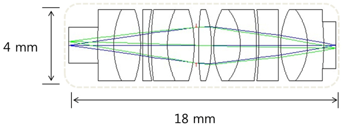
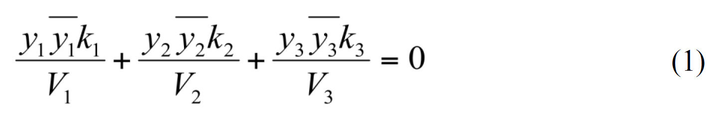
Unfortunately, optical aberrations of the lens become more severe as the optical power of the lens increases. In order to correct aberrations and improve lens performance,we split one lens into two or more lenses. Adding a negative lens and meniscus lenses decreases the total optical aberrations[11]. We split the lens until each of the lenses had the proper optical power while the total optical power kept the same value. After splitting the lenses three times, we reached the proper design result, which constituted four lenses. An Amici type objective lens design is introduced for the probe lens design, because of its high performance and optical power. Four lenses replace commercial lenses to decrease the cost of the probe. However, since the aberrations are still severe and the imaging performance is poor, it is impossible to use this lens combination as an endo-microscope probe. Three other lenses are inserted between each commercial doublet lens to decrease the optical aberrations of the probe, and those three lenses are designed through a lens design optimization process. The constraints are the total length of the optical system, the number of lenses and the lens diameter, etc., and the curvature of the lens, the material properties of the glass and the distance between the lenses are selected as variables.Optimization is performed mainly to minimize chromatic aberrations and spherical aberrations. By adjusting the Abbe number and the partial dispersion of each lens, chromatic aberrations and spherical aberrations can be corrected [12].With some assumptions and derivations, the conditions for apochromatic lens are given by equation (1) where k is Refractive power, y is Marginal ray height, ? is Full-field chief ray height and V is Variance of a material.
By changing the material of three customized lenses that are inserted between four commercial lenses, the chromatic
[TABLE 1.] Result of the optimization process of the probelens design
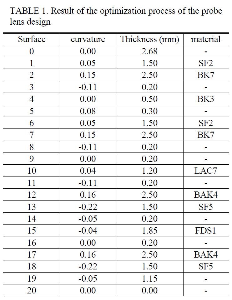
Result of the optimization process of the probelens design
aberrations of the probe are decreased significantly. FIG. 1 and Table 1 show the result of the optimization of the probe.
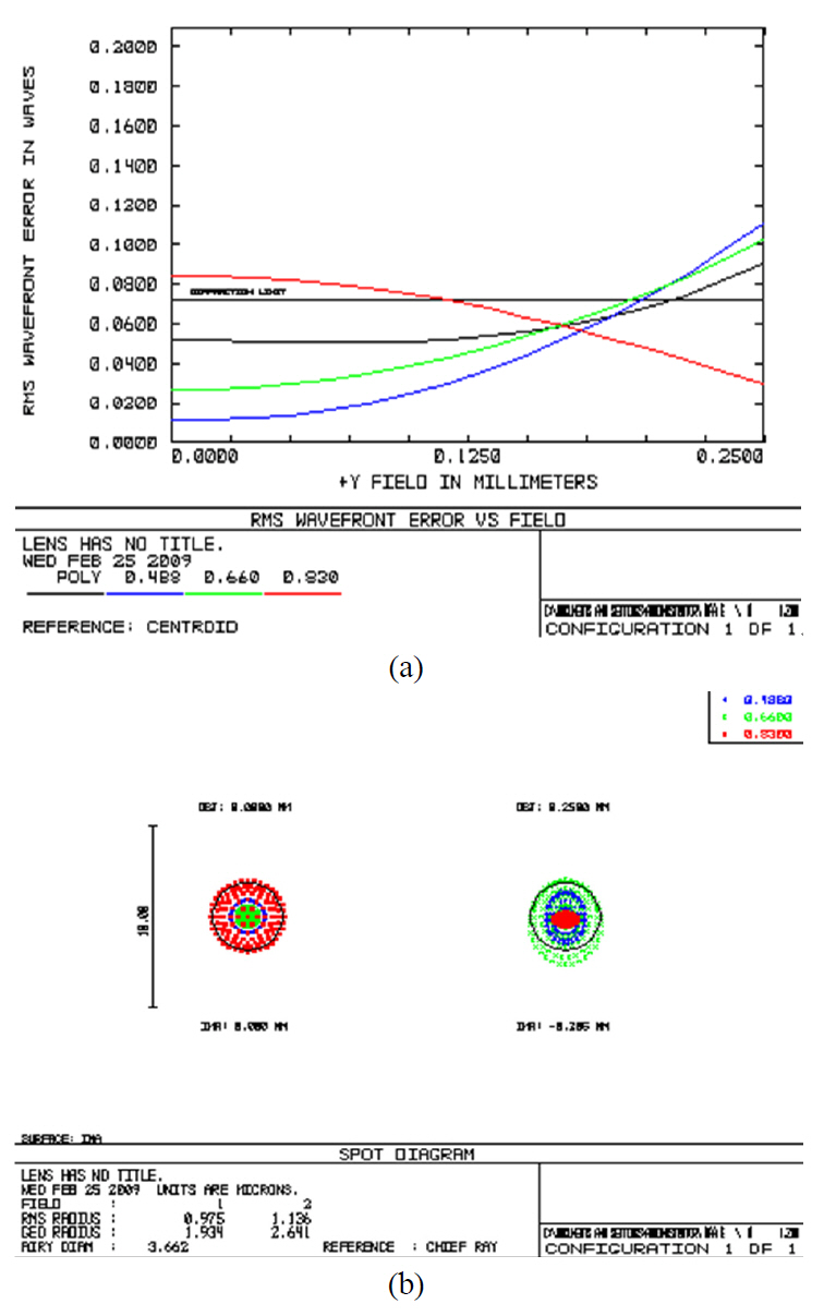
The proposed endo-microscope probe has better optical properties than conventional single lenses or the GRIN lens (Gradient Index lens). Although the size of the GRIN lens is small enough to be used for an endo-microscope,the chromatic aberrations are very severe so the image quality is poor when the probe is used for a multi-modal microscope.FIG. 2 shows the optical properties of the proposed endo-microscope probe. Fig. 2 (a) shows the RMS wavefront error along the field angle and (b) is a spot diagram of the probe. The optical properties of the system exhibit better performance when the RMS wavefront error is lower than the diffraction limit and the spot diagram is concentrated inside of the diffraction limit circle. FIG. 2 shows that the proposed probe has acceptable optical properties to be used for a confocal endo-microscope probe.
There are three kinds of scanning mechanisms for endomicroscopes.The first type uses a fiber bundle for connecting the small probe with the microscope. The second type uses
a MEMS scanner for optical scanning [13]. MEMS technology is widely used for optical systems because it has many applications for optical components like optical grating.Moreover, a MEMS scanner can be made small enough to be compatible with an endo-microscope. The third type uses fiber dynamics for scanning [14]. Since the image guide fiber bundle type microscope has the advantages of safety and robustness, the proposed endo-microscope is designed to function as the first type of endo-microscope.
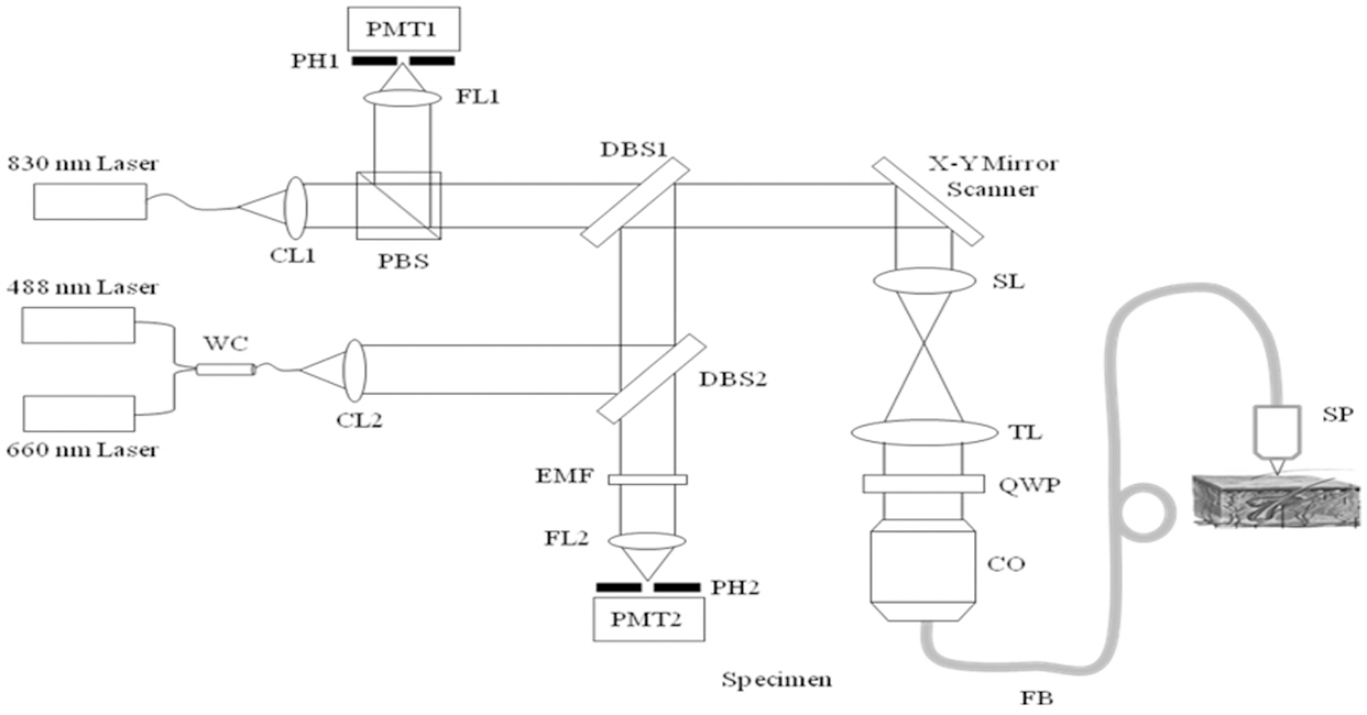
The schematic diagram of the proposed endo-microscope is illustrated in FIG. 3. A normal multi-modal confocal microscope is used for the base system. The multi-modal confocal microscope has 488 nm and 660 nm lasers for the fluorescence mode and a 830 nm laser as a reflection microscope. Since the microscope uses two different laser sources for the fluorescence mode, a dichroic beam splitter and emission filter are used to detect different fluorescence signals from the samples.
Reflection A reflection microscope uses a polarization state for excitation and detection. The linearly polarized beam state is rotated by 90° by passing through a quarter wave plate during the excitation and emission. The polarizing beam splitter separates the emission beam so that the detector can detect the reflected beam only. An X-Y scanning mechanism is inserted inside the confocal microscope and it scans the surface of the fiber bundle. As the focal spot moves on the surface of the fiber bundle the excitation light moves along the core and illuminate the sample through the probe. Emission or reflected light is refocused on the surface of the fiber bundle by the small probe and is transited to the other side along the fiber. By detecting the light signal of each core, the confocal microscope constructs images.
The Rayleigh criterion is generally accepted as the standard for lateral resolution of an optical system. The lateral resolution is represented by
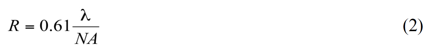
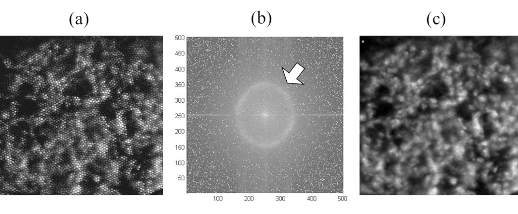
The NA of the probe at the sample space is 0.25, so the lateral resolution is about 1.6 ㎛ (at a 660 nm wavelength),but the lateral resolution of the endo-microscope is about 3.3 ㎛. Since the magnification factor of the probe is 1.2 and the distance between the two cores in the transition area of the fiber bundle is 4 ㎛, the distance between two dots in the image is 3.3 ㎛, which is the resolution of the endo-microscope. Because of a pixilation problem, the final image of the endo-microscope contains the fiber bundle image. Since the fiber cores in the fiber bundle have the same size and are arranged with a particular pattern, the fiber bundle image can be extracted from the image by optical processing.FIG. 4 shows the spatial frequency of the fiber bundle after the Fast Fourier Transform. The arrow represents the spatial frequency of the fiber bundle and the frequency component is removed by a Gaussian filter, so that the fiber bundle image is removed from the endo-microscope images.
III. EXPERIMENTAL RESULTS FOR THE ENDO-MICROSCOPE
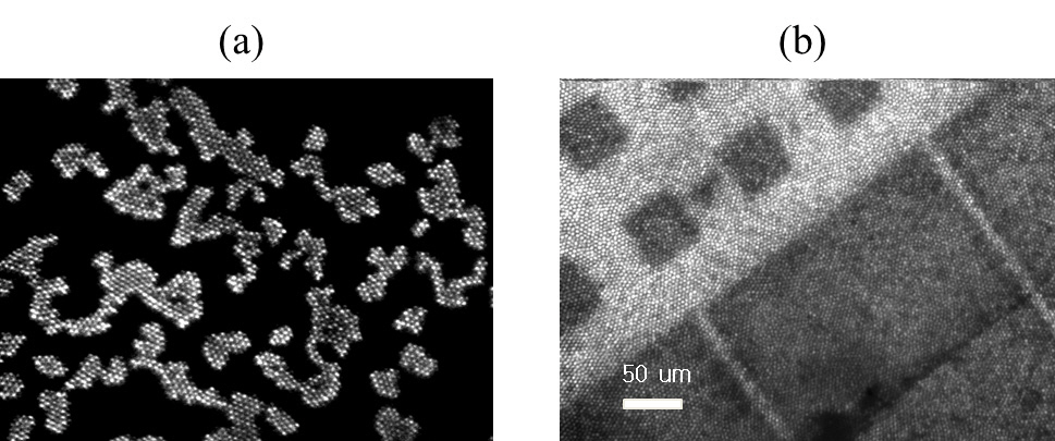
Fluorescein sodium and acridine orange were used as fluorescence dyes. Since fluorescein is a nontoxic dye, it is normally used for bio-medical imaging. Since most of fluorescence dye has an excitation wavelength within the visible wavelength range, an 830 nm laser is used as reflection microscope. FIG. 5 shows the endo-microscopic images of the fluorescence and reflection modes. The sample for the fluorescence endo-microscope is a fluorescent bead with a diameter of 6 ㎛, whose center wavelength of the emission is 515 nm (InSpeck Green Microscope Image Intensity Calibration Kit, Invitrogen) (see FIG. 5 (a)). The reflection sample is a standard target with a square of 50 ㎛ and a line of 10 ㎛ (see FIG. 5 (b)).
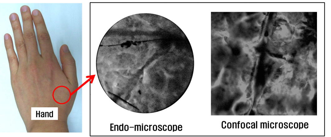
An in-vivo endo-microscopic image of a human hand is compared with another image of a human hand using the confocal microscope (FIG. 6). The FOV of the two images were adjusted to have the same scale. Because of legal issues, we were limited to investigating only the possibility of in-vivo medical imaging in this research. Further studies
should be performed after solving the legal issues.
FIG. 4 presents an ex-vivo image of mouse lung. As mentioned above, the fiber bundle consisted of 30,000 cores,and the final image of the sample had a pixilation problem.The fiber bundle pattern was removed by optical processing.The performance of the proposed endo-microscope was evaluated by analyzing the acquired images. The lateral and axial resolutions are illustrated in FIG. 7. The lateral resolution of the probe is limited by the distance between the two fiber cores at the image transition area of the bundle.Since the distance between the two cores was 4 ㎛, the lateral resolution of the endo-microscope was about 3.3 ㎛. The original lateral resolution of the probe with the NA of 0.3 was smaller than 3.3 ㎛, but the real value is meaningless for the nyquist frequency of the fiber bundle.
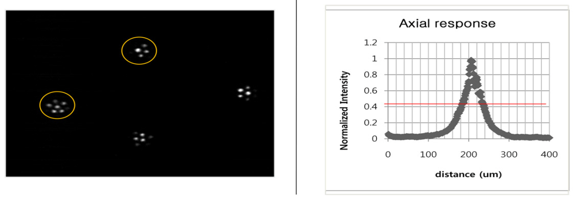
To measure the lateral resolutions of the probe, we used a fluorescent bead with a diameter of 6 ㎛. Since the diameter of the bead was 6 ㎛, the bead is represented with three or four dots (six maximum) by the endo-microscope (see FIG. 7 (a)). The axial resolution was evaluated by measuring the intensity profile of the reflected light while moving a plane mirror along the optical axis. The full width at half maximum (FWHM) value was selected to evaluate the axial resolution. The axial resolution was about 50 ㎛,which is quite large for optical sectioning of the specimen,but this meets the desired specifications of the probe.
We proposed a multi-modal confocal endo-microscope that is capable of fluorescence and reflection imaging. In the reflection imaging mode, a laser with a wavelength of 830 nm was used. In the fluorescence imaging mode, two lasers with wavelengths of 488 nm and 660 nm were used.A small endo-microscopic probe was designed to decrease chromatic and spherical aberrations and was connected to a multi-modal confocal microscope with an image guide fiber bundle. In-vivo images of a human hand and ex-vivo image of a fluorescent bead and mouse lung were obtained by the fluorescence mode confocal endo-microscope. A standard target with squares of 50 ㎛ and lines of 10 ㎛ was used to obtain the image of the reflectance mode. Reflectance and fluorescence images were obtained with a GRIN lens and an aspheric lens and were compared with the proposed endo-microscope probe. The proposed endo-microscope probe showed better image quality in sharpness and contrast. The optical performance of the endo-microscope was evaluated by analyzing acquired images of the fluorescent bead and standard target. The proposed endo-microscope had a lateral resolution of 3.3 ㎛, which was the sampling rate of image with respect to the probe magnification factor and the fiber bundle core distance and axial resolution of 50 ㎛. The proposed multi-modal confocal endo-microscope had an image acquisition speed of 30 frame/sec, which was fast enough to get real time in-vivo images. Although most of images in this research were ex-vivo, it will be possible to get in-vivo medical images using the proposed endomicroscope by reducing the lens size and the length of the fiber bundle. Because of the current regulations for medical application, it is difficult to apply the proposed endo-microscope system to the human body right now, but approval of the proposed confocal endo-microscope is in progress. Further research to miniaturize the endo-microscope probe while increasing the optical performance should be achieved for clinical trials and commercialization of the confocal endomicroscope.