검색 전체 메뉴
PDF
맨 위로
OA 학술지
Effect of Fiber Dispersion and Self-phase Modulation in Multi-channel Subcarrier Multiplexed Optical Signal Transmission
  • 비영리 CC BY-NC
  • 비영리 CC BY-NC
ABSTRACT
Effect of Fiber Dispersion and Self-phase Modulation in Multi-channel Subcarrier Multiplexed Optical Signal Transmission
KEYWORD
Subcarrier multiplexing , Dispersion , Self-phase modulation , Radio-over-fiber , (060.2330) Fiber optics communications , (060.2360) Fiber optics links and subsystems , (060.4510) Optical communications
  • I. INTRODUCTION

    Radio over fiber (RoF) technology has received much interest in order to accommodate demands for increased bandwidth and diversity of services [1?2]. The advantage of RoF technology is the use of an optical fiber with low loss and wide bandwidth for signal transmission. The use of RoF technologies can reduce the size of radio base stations (RBSs) because each RBS needs only a device for optical-to-electrical conversion. Moreover, since the radio modulation unit is located at the control station (CS), the RBSs can use the same frequency band to transmit their radio signals.

    RoF technology is often considered one of the simplest solutions to providing future wireless broadband access, and an RoF system including wireless communication systems has recently been proposed [3]. In multi-service environments,the transmission capacity and the number of users in a RoF network can be increased by using sub-carrier multiplexing(SCM) technology that enables multiple RF signals to be transmitted simultaneously over fiber-optic links.

    However, when either the subcarrier frequency or the required transmission distance is large, the quality of the signal becomes degraded due to the impairment from the optical fiber channel such as the fiber nonlinearities [4] and the dispersion-induced power penalty (DIPP) that alters the first null point of the fiber transmission response dependent upon the subcarrier frequencies and transmission distance[5]. Although the self-phase modulation (SPM)-induced fiber dispersion compensation effect in millimeter-wave optical transmission systems has been investigated [6,7], the analysis has been limited to transmission systems with a single subcarrier. In this paper, we investigate, for the first time to our knowledge, the combined effect of fiber dispersion and SPM in multi-channel optical SCM transmission systems by theoretical analyses and numerical simulations.

    We performed simulations of a two-channel SCM signal and calculated the RF power of the subcarrier signals under various SCM transmission environments, including the effects of fiber dispersion and SPM. From the simulated data, we investigate the effect of the optical modulation index (OMI),fiber launching power, and SCM channel spacing on the transmission of SCM signals.

    The objective of this paper is to theoretically investigate the combined effect of fiber chromatic dispersion and SPM in optical multi-channel SCM transmission systems.The transmission distance at P3dB after the SMF link with the fiber dispersion and SPM effects can be increased by applying higher fiber launching power into the fiber channel link. However, this gain can be degraded in multichannel environments by the interaction among the subcarrier signals especially at higher fiber launching power. Because it is very difficult to distinguish the origin of these effects in multi-channel environments, we performed numerical simulations using the two-channel SCM signals first to accurately investigate and understand the origin of their interactions.

    II. THEORETICAL ANALYSIS

    Several studies on the feasibility of fiber-induced SPM to compensate for fiber dispersion effects have been reported[6,7]. For a single SCM channel, the nonlinear phase shift induced by SPM at a propagation distance z and normalized time in a frame moving at the group velocity, T = t ? z / vg is expressed as [6]:

    image

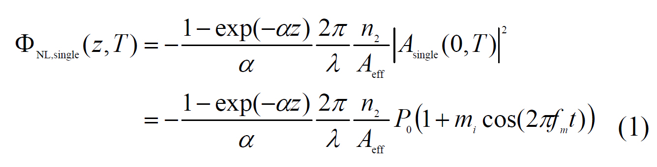
    with the field envelope at the fiber input, Asingle (0,T) = √P01+mi cos(2πfmt) where P0 is the optical power, mi is the optical modulation index, fm is the RF subcarrier frequency, α is the fiber attenuation coefficient, n2 is the nonlinear index coefficient, Aeff is the effective core area of the fiber, and λ is the wavelength of the optical carrier.

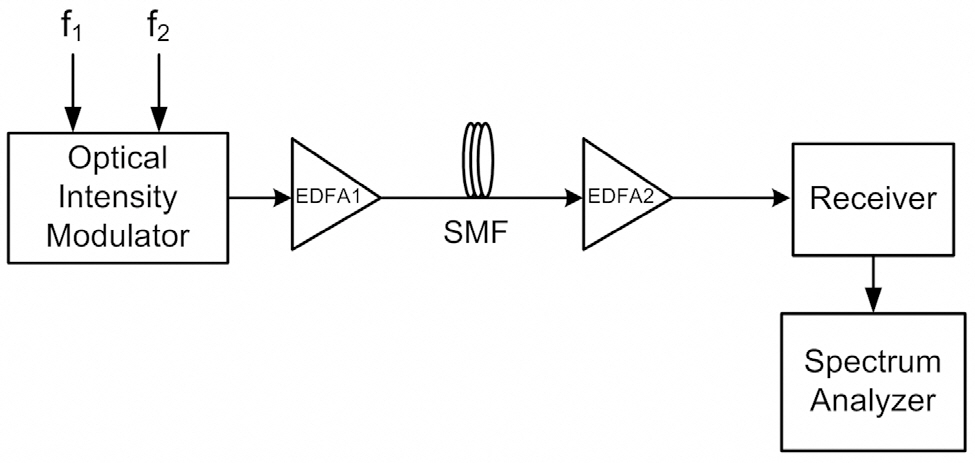
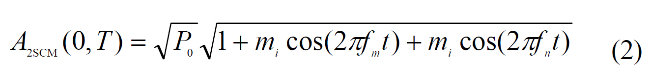
    For an SCM signal with two RF subcarrier channels(shown in Fig. 1), the initial pulse envelope and the nonlinear phase shift induced by SPM can be expressed as:
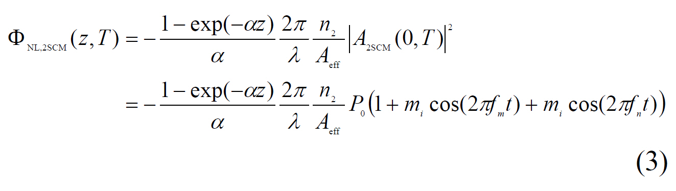
    image
    image

    where fm and fn are the two different RF subcarrier frequencies. We consider only two SCM channels in order to simplify the problem and minimize the computational expense.

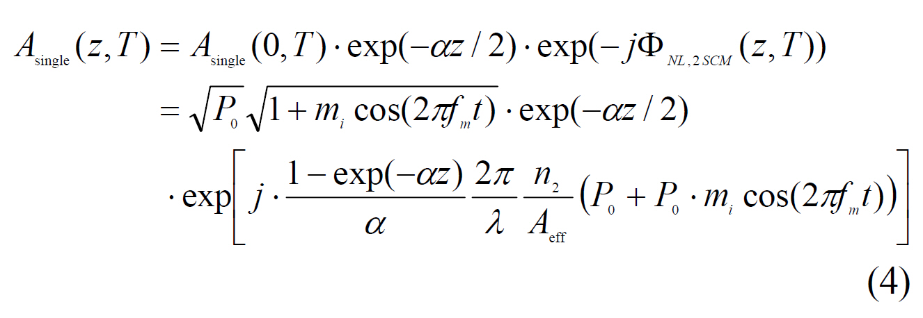
    The field of the signal with a single RF subcarrier,considering solely the effect of SPM, can be expressed as:

    image

    and the field of SCM signal with two RF subcarrier channels, considering the initial pulse envelope and the phase shift due to SPM, is expressed as:

    image

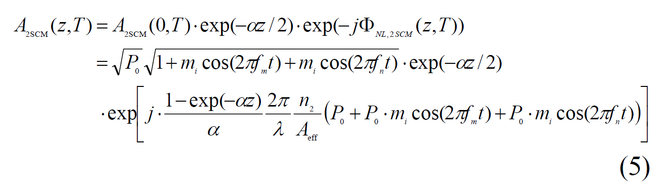
    The last term in Eq. (4) describes the phase shift induced by the SPM effect. It is well known that, in single channel SCM transmission system, the SPM-induced frequency chirp can compensate for the pulse distortion due to chromatic dispersion in a single-mode fiber (SMF) [6,7].However, in two-channel SCM transmission system, there is additional phase shift caused due to the other SCM frequency fn, as shown in Eq. (5). The additional phase shift depends on the optical modulation index, the fiber launching power, and the frequency. Therefore, there is some interaction between the different RF subcarrier channels, fm and fn, and this interaction can reduce the fiber dispersion compensation effect due to SPM-induced frequency chirp.The addition of extra SCM channels will cause more phase shift of the entire SCM signal envelope, as can be seen from the exponential term in Eq. (5). Therefore, the interaction among the subcarrier signals will be increased and the degradation of the SPM-induced fiber dispersion compensation effect will also be increased.

    III. SIMULATION METHOD

    As shown in Fig. 1, the RF subcarrier signals were modulated by an optical linear modulator in order to observe the effect of fiber transmission. The lasing wavelength was 1550 nm, and the electrical RF subcarrier signals were sinusoids. For an optical signal propagating in a nonlinear, dispersive, and lossy single-mode fiber, the evolution of a slowly varying electric field pulse envelope can be found from the nonlinear Schrodinger equation [8]. We performed numerical simulations to examine the combined effect of fiber dispersion and SPM by using the split-step Fourier method [8,9]. In order to vary the strength of the SPM effect, the fiber launching power entering the SMF

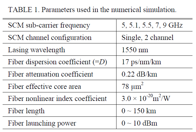
    [TABLE 1.] Parameters used in the numerical simulation.

    label

    Parameters used in the numerical simulation.

    was adjusted between 0 and 10 dBm using an optical amplifier before transmission. The length of the SMF was varied from 0 to 150 km in order to observe different fiber dispersion effects. We used the electrical power spectra calculated after detection with a photodiode to calculate the RF carrier power of each SCM channel. The specific parameters of the optical fiber link used in our simulations are shown in Table 1.

    IV. NUMERICAL SIMULATION RESULTS

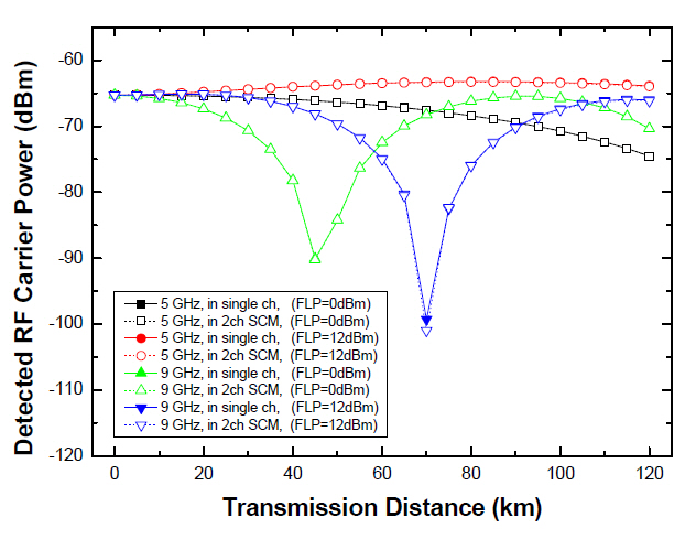
    First, we simulated two-channel SCM transmission systems with a large channel spacing, and investigated the combined effect of fiber dispersion and SPM. Two subcarrier signals at 5 GHz and 9 GHz were combined. The OMI per channel was 20% and the detected RF carrier power for each channel was calculated after transmission over an SMF link up to 120 km. We also simulated SCM systems with a single subcarrier for comparison. Fig. 2 illustrates the detected RF carrier power for the single- and two-channel signals. Due to the DIPP characteristic, the null point of the carrier power fading as a function of the transmission distance appeared first for the 9 GHz signal [5]. When the higher fiber launching power (10 dBm) was applied, the transmission distance at the same detected RF carrier power was extended for 5 GHz and 9 GHz signals. This is due to the fact that the chirping effect of SPM combines with the fiber dispersion, leading to dispersion compensation in the SMF transmission link [6, 7].

    However, the detected RF carrier powers for the singleand two-channel SCM signals were almost the same at the same subcarrier frequency and fiber launching power for all transmission distances. This is because the OMI per channel was relatively small and the channel spacing between the subcarrier channels was large. Therefore, there was little interaction between the subcarrier signals. The intermodulation product near two SCM channels was very small, even for an OMI per channel of 50%; therefore it can be expected that the effect of the nonlinear distortion after photo-detection in the receiver was also small.

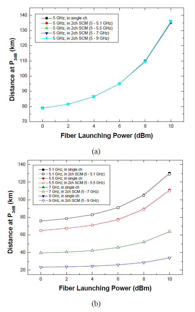
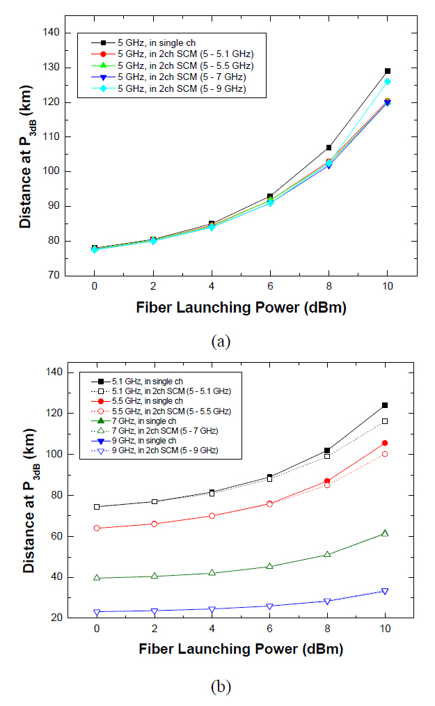
    We evaluated the transmission distances at which the detected RF carrier power dropped by 3 dB. These values are termed the “transmission distance at P3dB” in this paper.The value of P3dB was almost the same for different subcarrier frequencies; however, the RF carrier power fading curves varied with subcarrier frequency and fiber launching power. Therefore, the calculated transmission distance at P3dB also changed. As can be seen from the additional phase shift term in Eq. (5), the fiber launching power,OMI per channel, and SCM channel spacing are important parameters for evaluating the entire SCM transmission system performance. In order to confirm the effect of these parameters, the frequency of channel 1 was fixed at 5 GHz and the frequency of channel 2 was varied between 5.1 and 9 GHz. Two different simulation cases were considered.First, single- and two-channel SCM systems with an OMI per channel of 20% were evaluated in terms of the transmission distance at P3dB. Secondly, a performance evaluation was carried out again with an OMI of 50% in order to investigate the effect of OMI per SCM channel.

    Fig. 3(a) shows the transmission distance at P3dB for the subcarrier signals at 5 GHz with an OMI per channel of 20%. The transmission distance at P3dB increased with larger fiber launching power due to the dispersion compensation effect in combination with SPM. The calculated

    values were almost the same for the single- and two-channel configurations, even for different SCM channel allocations.Fig. 3(b) shows the transmission distance at P3dB as a function of fiber launching power when channel 2 was varied from 5.1 to 9 GHz, and with an OMI per channel of 20%.As the frequency of channel 2 increased, the transmission distance at P3dB fell due to the DIPP characteristic of the SMF link. Based on these simulation results, we can infer that the SCM channel spacing and fiber launching power do not result in serious performance deterioration for small values of the OMI per channel. It was shown that the performance of two-channel SCM systems was almost equal to that of single channel systems. This also follows from Fig. 2, because the combined effect of fiber dispersion and SPM occurred independently between the two SCM channels for small values of OMI per channel.

    Fig. 4(a) shows the transmission distance at P3dB of channel 1, and Fig. 4(b) shows the transmission distance at P3dB for channel 2, with an OMI per channel of 50%. The transmission distance at P3dB increased with increasing fiber launching power due to SPM-induced dispersion compen

    sation effect. However, the two-channel system showed a drop in the transmission distance at P3dB compared to the performance of the single channel configuration. Therefore,the addition of another SCM channel reduced the fiber dispersion compensation effect caused by SPM.

    From the analysis in Section 2, when the SCM signals have large OMI per channel and the channel spacing is small, the effect of the additional phase shift term in Eq.(5) is more pronounced. Therefore, the performance improvement due to the interaction between fiber dispersion and SPM can be reduced at high fiber launching powers.

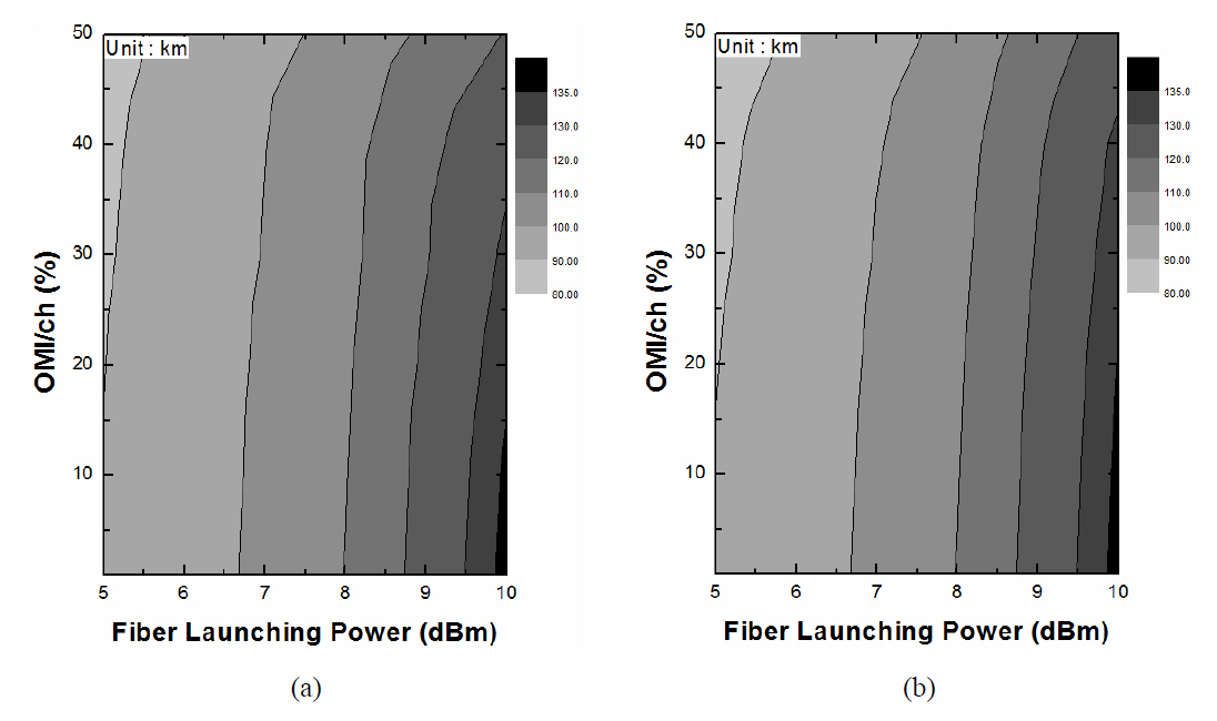
    Fig. 5(a) and (b) show the contour plots of the transmission distance at P3dB for the first SCM channel at 5 GHz when the second channel is at (a) 5.1 GHz and (b)9 GHz, respectively. Up to the OMI of 15%, there is no significant difference in the transmission distance at P3dB with varying the fiber launching power from 5 to 10 dBm because the interaction between the subcarrier signals is relatively small. However, when the OMI per channel is increased over 15%, the calculated value of the transmission distance at P3dB of the SCM signal with the SCM channel

    spacing of 100 MHz, as shown in Fig. 5(a), is degraded especially in the higher fiber launching power because the increased interaction between subcarrier signals can reduce the effect of SPM-induced fiber dispersion compensation.For example, when the OMI of 40% and the fiber launching power of 10 dBm are applied in the system, the SCM system with 100 MHz channel spacing (Fig. 5(a)) cannot guarantee the transmission distance at P3dB over 130 km,whereas the SCM system with 4 GHz channel spacing(Fig. 5(b)) can guarantee the performance. Therefore, we can suggest that the OMI should be smaller than 15% to provide similar transmission performance when the channel spacing is larger than 100 MHz and the fiber launching power is less than 10 dBm.

    V. CONCLUSION

    We investigated the combined effect of fiber dispersion and SPM in optical SCM transmission systems. From a theoretical analysis and numerical simulations, we found that the dispersion compensation effect in combination with SPM occurred independently for each subcarrier for a small OMI per channel and large channel spacing.

    We evaluated the performance of single-channel and two-channel SCM systems in terms of the transmission distances at P3dB. The simulated data showed that the dispersion compensation effect due to SPM increased for high fiber launching powers for both cases. However, the transmission distances at P3dB of the two-channel SCM system was reduced compared to that of the single-channel system,especially at higher fiber launching powers and smaller SCM channel spacing. This resulted from the increased interaction between subcarrier channels due to the effect of an additional phase shift caused by the other channel. This interaction reduced the SPM-induced fiber chromatic dispersion compensation effect in multi-channel SCM systems.This result can be used for the optimization of multi-service systems using SCM technology in future RoF networks.

참고문헌
  • 1. Morita K, Ohtsuka H 1993 The new generation of wireless communication based on fiber-radio technologies [IEICE Trans. Commun.] Vol.E76-B P.1061-1067 google
  • 2. Hong M. K, Han S. K, Lee S. H 2007 Linearization of DFB LD by using cross gain modulation of reflective SOA in radio-over-fiber link [J. Opt. Soc. Korea] Vol.11 P.158-161 google cross ref
  • 3. Hwang S. T, Kim H, Kim B. J, Kim S. K, Lee J. H, Lee H. L, Kim Y. G, Lee G. W, Kim S. H, Oh Y. J 2007 RoF technologies for in-building wireless systems [IEICE Trans. Electron.] Vol.E90-C P.345-350 google cross ref
  • 4. Jang H. D, Kim K. S, Lee J. H, Jeong J. C 2009 Transmission performance of 40 Gb/s PM duobinary signals due to fiber nonlinearities in DWDM systems using VSB filtering techniques [J. Opt. Soc. Korea] Vol.13 P.354-360 google cross ref
  • 5. Fuster J. M, Marti J, Corral J. L, Polo V, Ramos F 2000 Generalized study of dispersion-induced power penalty mitigation techniques in millimeter-wave fiber-optic links [IEEE J. Lightwave Technol] Vol.18 P.933-940 google cross ref
  • 6. Ramos F, Marti J, Polo V, Fuster J. M 1998 On the use of fiber-induced self-phase modulation to reduce chromatic dispersion effects in microwave/millimeter-wave optical systems [IEEE Photon. Technol. Lett.] Vol.10 P.1473-1475 google cross ref
  • 7. Ramos F, Marti J, Polo V, Fuster J. M 2000 Dispersiontolerant data transmission based on the use of fiber-induced self-phase modulation in microwave optical links [Microwave Opt. Technol. Lett.] Vol.27 P.1-4 google cross ref
  • 8. Agrawal G. P 1989 Nonlinear Fiber Optics google
  • 9. Lee J. H, Kim S. K, Kim Y. G, Mizuhara O, Lyu G. Y, Kang S. S, Song J. H, Jeong J. C 2001 Performance evaluation and prediction using eye margin characteristics for optical transmission systems [Opt. Comm.] Vol.193 P.113-120 google cross ref
이미지 / 테이블
  • [ FIG. 1. ]  Schematic diagram of the SCM transmission link.
    Schematic diagram of the SCM transmission link.
  • [ TABLE 1. ]  Parameters used in the numerical simulation.
    Parameters used in the numerical simulation.
  • [ FIG. 2. ]  Detected RF carrier power versus transmissiondistance for single- and two-channel SCM signals; 5 GHzand 9 GHz.
    Detected RF carrier power versus transmissiondistance for single- and two-channel SCM signals; 5 GHzand 9 GHz.
  • [ FIG. 3. ]  Transmission distance at P3dB for the SCM signalswith 20% OMI per channel. (a) Channel 1 (5 GHz) and (b)channel 2 (5.1 ? 9 GHz).
    Transmission distance at P3dB for the SCM signalswith 20% OMI per channel. (a) Channel 1 (5 GHz) and (b)channel 2 (5.1 ? 9 GHz).
  • [ FIG. 4. ]  Transmission distance at P3dB for the SCM signalswith 50% OMI per channel. (a) Channel 1 (5 GHz) and (b)channel 2 (5.1 ? 9 GHz).
    Transmission distance at P3dB for the SCM signalswith 50% OMI per channel. (a) Channel 1 (5 GHz) and (b)channel 2 (5.1 ? 9 GHz).
  • [ FIG. 5. ]  Contour plots of Transmission distance at P3dB calculated from the first SCM channel fixed at 5 GHz while the second SCMchannel is varied at (a) 5.1 GHz and (b) 9 GHz.
    Contour plots of Transmission distance at P3dB calculated from the first SCM channel fixed at 5 GHz while the second SCMchannel is varied at (a) 5.1 GHz and (b) 9 GHz.
(우)06579 서울시 서초구 반포대로 201(반포동)
Tel. 02-537-6389 | Fax. 02-590-0571 | 문의 : oak2014@korea.kr
Copyright(c) National Library of Korea. All rights reserved.