As data traffic demands increase rapidly, optical communication systems are widely used, providing high data rates with a large number of channels per fiber. However, optical fiber communication systems suffer from various linear and nonlinear transmission impairments [1]. Chromatic dispersion(CD) and polarization mode dispersion (PMD) are two important factors degrading the performance of high speed optical fiber transmission systems [2]. Intersymbol interference(ISI) caused by CD, PMD, and other impairments increases bit error rate (BER). As the transmission rate increases, ISI mitigation becomes indispensable and many schemes for CD and PMD compensation have been proposed. These compensation techniques can be separated into two approaches;optical domain equalization [3] and electrical domain equalization[2, 4, 5]. Optical equalization schemes can achieve perfect compensation using inverse system response, while the performance of electrical domain equalization is limited due to the nonlinear channel effect caused by the photodetector,which is a square-law detector. Nonetheless, electrical domain equalization schemes are widely used thanks to the multiple advantages, including compactness, flexibility, and low cost, that are brought by high-speed integrated-circuits technology.
Until now, most work on electronic domain equalizers has been focused on experimental studies [2, 5, 6]. The equalizer coefficients are determined by adaptive algorithms such as least mean square (LMS) algorithms and recursive least square (RLS) algorithms [7]. The obtained minimum mean square error (MMSE) solutions for optical on-off-keyed(OOK) systems have not been confirmed by theoretical studies.In this paper, we present theoretical closed form expressions for the MMSE linear equalizer coefficients and their MMSE performance. Through simulation, we verified that the calculated equalizer coefficients coincide with estimated equalizer coefficients using adaptive algorithm. Furthermore, once the MMSE equalizer coefficients are obtained, it is possible to estimate MSE performance of the MMSE linear equalizers in square-law nonlinear channels.
The rest of the paper is organized as follows. The next section describes the system model and computation of MMSE linear equalizer in square-law nonlinear channels.Simulation results using optical communication system are discussed in Section III. Section IV concludes the paper.
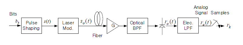
Consider a typical non-return-to-zero on-off-keyed (NRZ-OOK)optical communication model in Figure 1.
The bit sequence {
and transmitted over an optical fiber after laser modulation.We assume the fiber is a lossless linear channel with CD and first order PMD distortion. The CD and PMD are generally non-linear distortions, but often modeled as a linear distortion by a first order approximation in the optical field domain.The effect of dispersion can be modeled as a linear filtering process given by
where
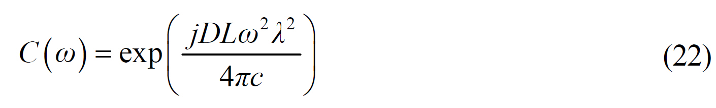
For example, the first-order PMD including CD distortion can be characterized as the following frequency response [2]
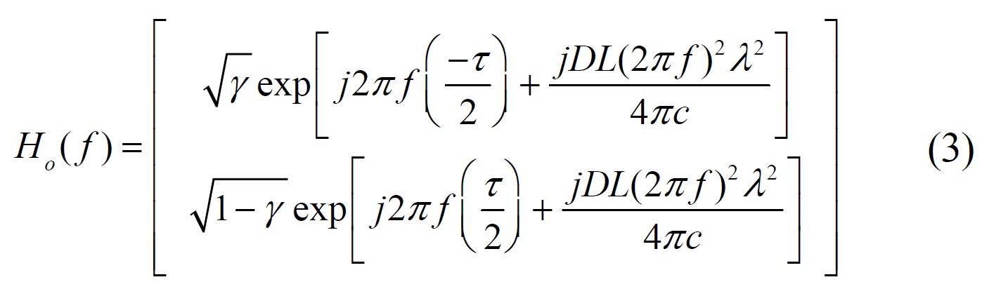
where L denotes the fiber length, λ the wavelength, D the dispersion parameter at λ, and c speed of light, γ the power splitting ratio, telling how the power of the input light of the fiber is divided onto the two input principle state of polarization, and τ denotes the differential group delay between the two polarizations.
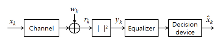
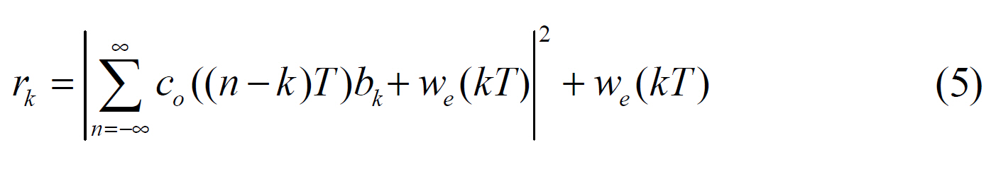
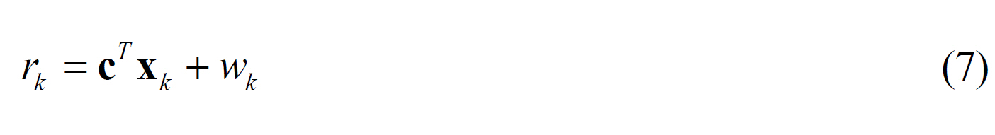
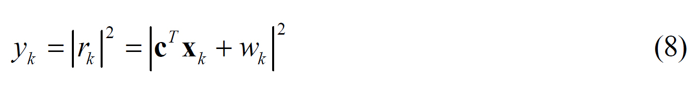
The received optical signals having undergone these dispersions are demodulated to electronic signal by a squarelaw detector. In contrast to the signal detection process in wireless communication systems, this process is nonlinear.Hence, the linear convolution relation in optical field domain is not preserved in the baseband electronic domain.The received signal in electronic domain is
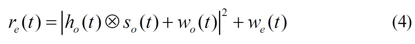
where
where
We assume that the transmitted signal
In contrast to the case in conventional wireless communication systems, the source signal
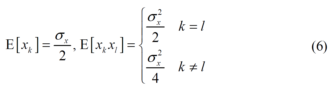
where E[·] denotes the expectation.
Denoting xk = [
And the input to the linear equalizer is given by
Let f = [
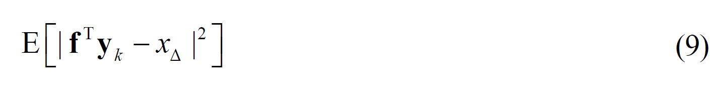
where
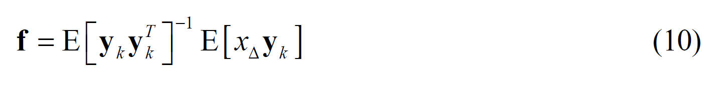
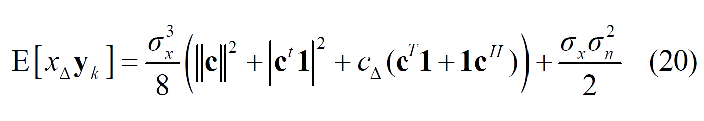
The goal of this paper is to express E[
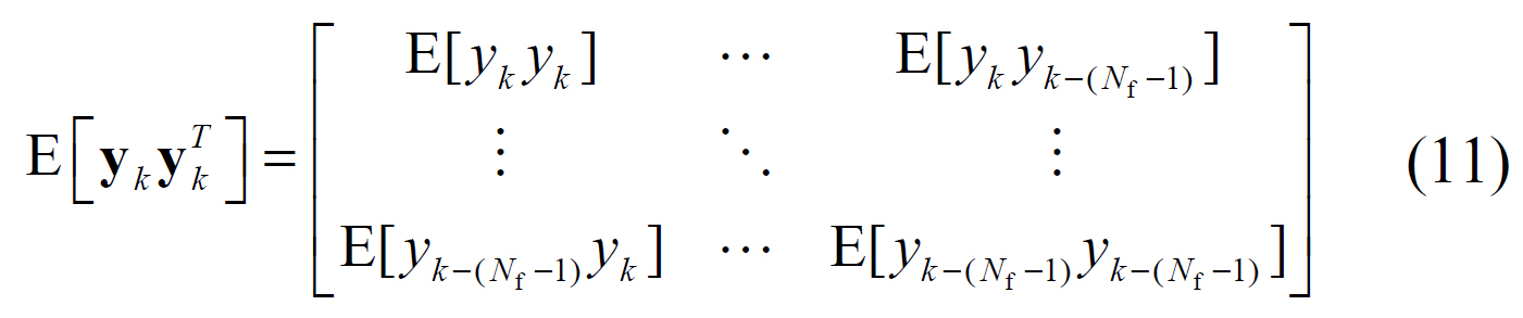
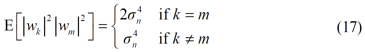
We know that E[
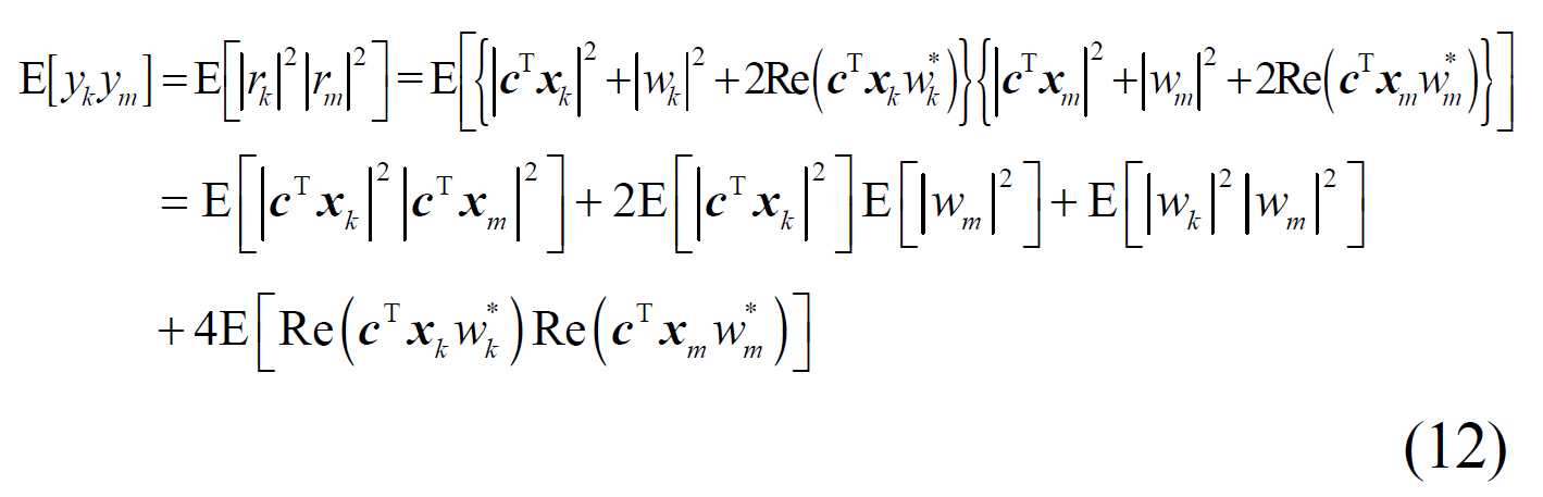
Let’s define the first term of E[yk ym],
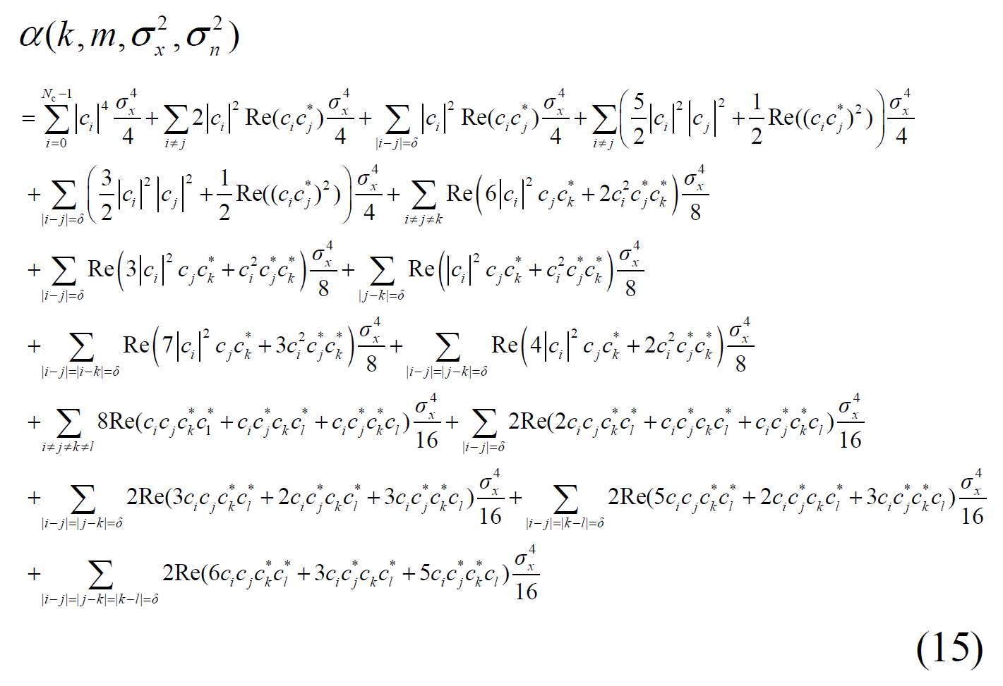
as a function
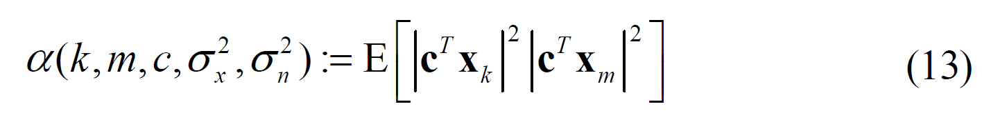
When
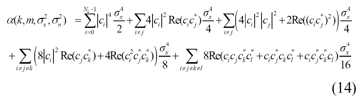
When '
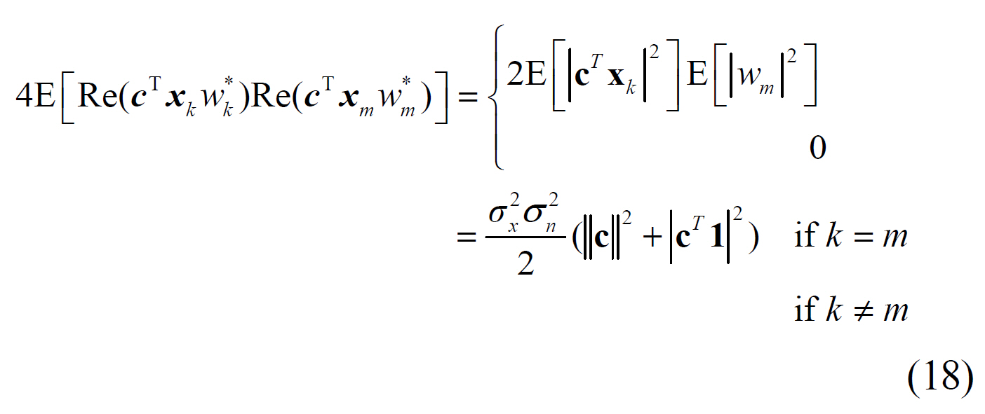
The second term is a product of two expectations
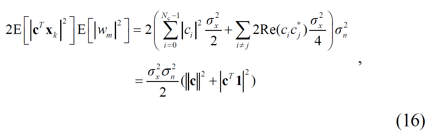
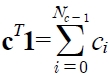
where 1=[1,…,1]T is the vector of length Nc consisting of 1’s. Note that
The third term, the noise term, can be expressed as the square of noise variance.
The last term becomes the second term, when
Now, we have obtained the element of E[
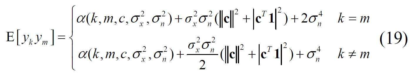
Consequently, we have obtained E[
Once equalizer tap coefficients are obtained, the MSE performance of the linear equalizer can be calculated by substituting equalizer tap f into the MMSE cost function.
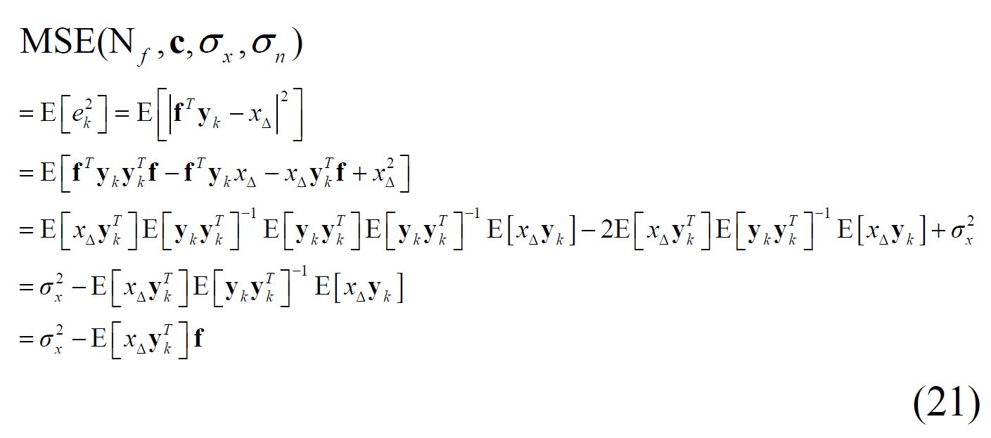
Once optical channel, optical noise variance, and the signal magnitude are given one can determine the MMSE equalizer and its MMSE performance. Numerical program languages such as Matlab are quite helpful to utilize the above results.
We consider mainly CD distortion to demonstrate the analysis on the electronic MMSE linear equalizers for optical OOK. In the frequency domain, the optical channel is given as
where the fiber CD parameter D is set to 17ps/nm/km,
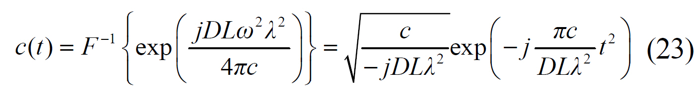
In order to produce a discrete time channel impulse response, continuous time transfer function is sampled at a rate of 1/
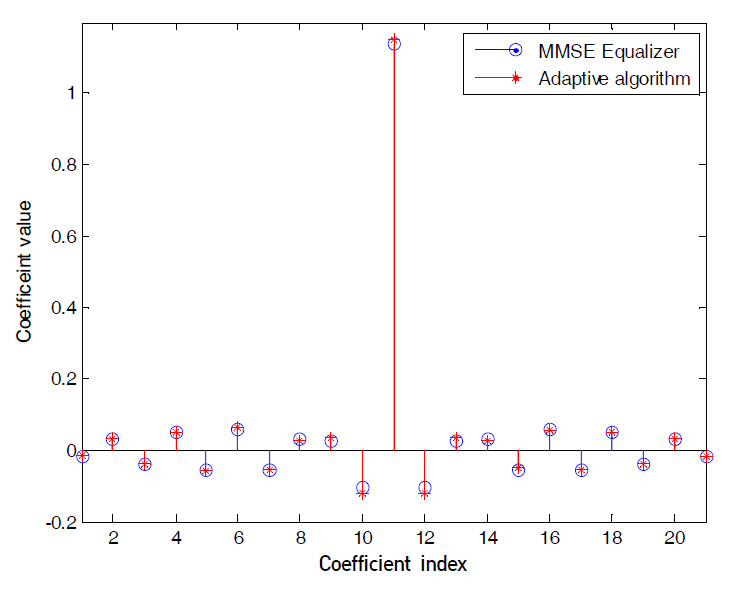
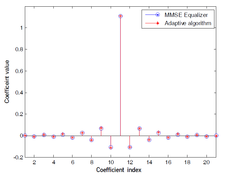
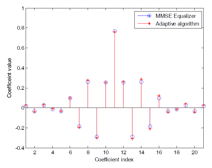
Fig. 3~5 compare the MMSE equalizer coefficients of
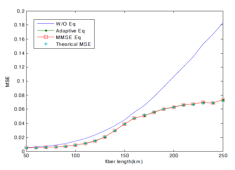
Fig. 6 shows that the MSE performances of two equalizers also agree. This result suggests that the MMSE performance of a linear equalizer for CD can be analytically computed instead of adaptive simulation.
We have performed analysis on the MMSE linear equalizer in square-law nonlinear channels found in optical OOK system and presented the MSE performance of equalizer. It has been verified that the analytically driven equalizer is indeed the MMSE solution by comparing with simulated equalizers by adaptive algorithms. As a result,we are able to theoretically bound MMSE performance of the electronic domain linear equalizer applied to optical OOK systems.