검색 전체 메뉴
PDF
맨 위로
OA 학술지
Symmetry Exploitation of Diffraction Gratings to Enhance the Spectral Resolution
  • 비영리 CC BY-NC
  • 비영리 CC BY-NC
ABSTRACT
Symmetry Exploitation of Diffraction Gratings to Enhance the Spectral Resolution
KEYWORD
Diffraction grating , Translational symmetry , Spectral resolution , Spectrometer , (050.1950) Diffraction gratings , (300.6190) Spectrometers , (300.3700) Linewidth
  • I. INTRODUCTION

    The diffraction grating consists of many grooves that are regularly spaced on a substrate surface. The spatial period of the groove lines typically ranges from one to several wavelengths of incident light. The wavefront of incident light falling on a grating surface is divided into many pieces, one at each groove line. The outgoing wavefront in a particular direction after the diffraction is composed of many interfering components from each groove line. Consequently,the direction in which all components are in phase is highly dependent on the wavelength of the incident light.In the years since its utility in the dispersion of multi-wavelength-component light was identified, it has been widely used for spectroscopy [1]. A tremendous number of spectroscopic applications are based upon grating-equipped spectrometers,including Raman scattering studies of molecular vibrational modes [2-4], fluorescent emission measurements of biological and chemical samples [5, 6], and optical spectrum analysis of photonics devices [7]. More recently,the diffraction grating has been found to be useful in the application of short laser pulse manipulation [8]. In this application, a multi-frequency-component short pulse laser beam is dispersed by a grating and focused on the Fourier plane, where each frequency component is controlled by a spatial light modulator to produce a variety of different shapes of laser pulses from the initial pulse after recombination through a second grating. This grating-based pulse manipulation has been widely adopted in chirped pulse amplifications to achieve high peak intensity laser beams[9, 10].

    The spectral resolution of the diffraction grating is limited by the number of grooves that are covered by the incident beam [11], which is analogous to the diffraction-limited spatial resolution governed by the numerical aperture of the objective lens in optical imaging systems . Therefore,to achieve a high resolution, gratings are required to either be of a very large size or to have a high groove density.However, the high-precision ruling process can make this a difficult task. In this study, intrigued by the translational symmetry that is intrinsically imposed on the diffraction grating, we exploit the symmetry and present a very simple method to exhibit unprecedented spectral resolution with a limited groove number.

    II . SYMMETRY OF DIFFRACTED FIELDS AND A PLANE-PARALLEL MIRROR PAIR AS A FIELD TRANSLATOR

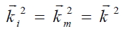
    To exploit the intrinsic translational symmetry of diffraction gratings, we first want to have a close look into the field structure around a grating that is illuminated by a plane wave of wavelength λ. As the grating itself and the incident field are translationally invariant upon a x-directed movement,as depicted in Fig. 1(a), the diffracted fields above the grating surface that consist of many diffraction orders have translational symmetries along the x-direction. Throughout the discussions following, we choose a transmission grating and scalar fields for the sake of convenience. Provided that the m-th order diffracted field ?m(□) is a solution to the Helmholtz equation (∇2+k2)?m = 0 with appropriate boundary conditions, the field translated in space by

    image

    is also a solution because of the invariance of the equation under the translational operation; that is,

    image

    The plane wave solution ?(□) around the grating can be expressed below and above the grating as

    image
    image

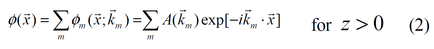
    where □i is the wavevector of the incident field below the grating, □m is that of the m-th order diffracted field above the grating, and

    image

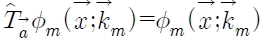
    If we apply the translation operator

    image

    to the fields, then

    image

    transforms to exp

    image

    where □ is a displacement vector. Generally, the field translation is accompanied by the phase shifts of wave functions.To realize the translational operation on the fields, we now consider an imaginary two-mirror element that has two large plane-parallel mirrors that are separated by a certain distance d and reflect electromagnetic fields just twice:only once at each mirror, with no multiple reflections, as shown in Fig. 1(b).

    Thus, any point in the fields is shifted in space by twice the mirror separation, ?□?=2d, as indicated by the red arrow in the figure. Assuming that the phase of the field is not changed upon reflection, the mirror pair acts purely as a field translator. Eventually, we would like to identify a condition for the mirror separation and the slanting angle where both the diffracted original fields and the translated fields have the same phases. Then, the translated field will be exactly equivalent to the original field; that is,

    image

    everywhere in the space.For this condition, we should satisfy the following relations from Fig. 1(b):
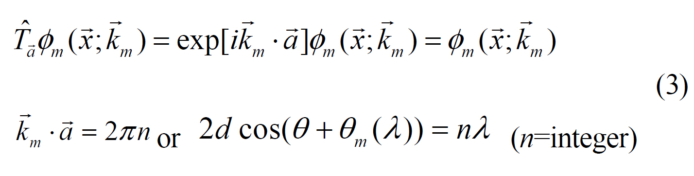
    image

    where θm(λ) is the m-th diffraction angle, d is the mirror

    separation, and θ is the slanting angle of the mirror pair.Simultaneously, we also require the fields to satisfy the grating equation, which is b(sinθm - sinθi (λ))=. Here, b is the grating period and θi is the incident angle. Eq.(3) is the phase matching condition between the original and the translated fields. It is an identity relationship that should be satisfied for the arbitrary wavelength λ. Using the trigonometric identity sin(θ -90)=-cosθ, Eq. (3) can be expressed as 2d sin(θ -90+θm(λ))=-. As the equation is satisfied simultaneously with the grating equation for every wavelength λ, we conclude that θ = 90, θi = 0°, and 2dm =-nb. As n is an integer, the result implies that to fulfill the phase matching condition for all diffraction orders starting from the first order, the field translation □ should be a horizontal shift (i.e., along the grating vector) by multiples of the grating period. This is what we can expect intuitively,and it is the same effect as would occur if the grating were translated by multiples of the grating period. The translational symmetry does not allow us to distinguish the original grating from the shifted grating.

    III. BEYOND THE LIMIT ON THE SPECTRAL RESOLUTION OF DIFFRACTION GRATINGS

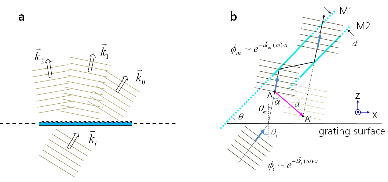
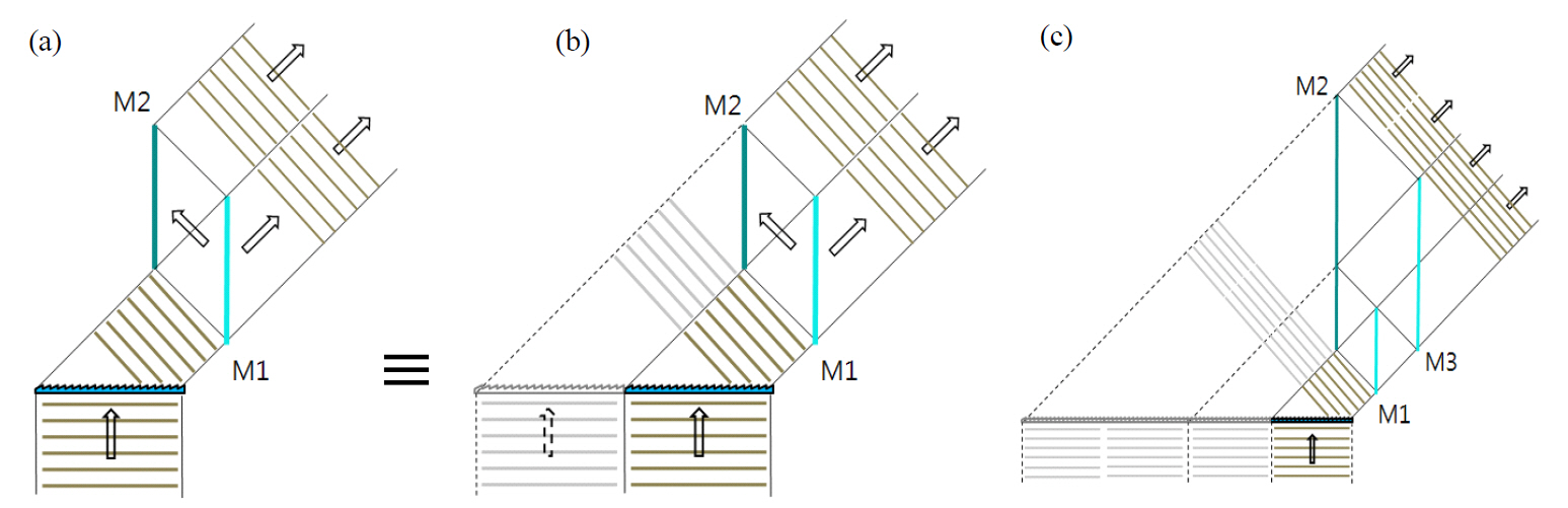
    To exploit the symmetry nature of the fields that are formed around a grating system, we propose an optical configuration,as shown in Fig. 2(a), where a plane wave of wavelength λ is incident on a grating plane and diffracted. We restrict the discussion to m = -1. The optical setup simply consists of one full mirror M2 and one half mirror M1 (50%reflectivity) which are parallel to each other and separated by d = nb/2, where n is the number of grooves covered by the incident beam. The mirror planes are perpendicular to the grating plane and the angle of incidence is zero to fulfill the conditions obtained in the previous section. Half

    of the diffracted beam transmits through the half mirror.The other half is reflected toward the full mirror and is reflected again from the full mirror to become parallel to the transmitted beam. Consequently, the second half of the diffracted beam is the field translated by the mirror pair,which has the same phase and intensity as the first half.Therefore, the corresponding equivalent grating system can be depicted as shown in Fig. 2(b). The system works in a manner such that half of the original field and the other half of the field that is translated by 2d interact to provide a larger aperture grating system. This system effectively doubles the number of grooves that are covered by the incident beam. The two-mirror configuration can be repeated once more by adding one more full-half mirror combination,and it consequently enhances the spectral resolution to quadruple that of the original diffraction grating. This concept is illustrated in Fig. 2(c), where the size of half mirror M3 is two times larger than that of mirror M1, and mirror M2 is extended to cover the reflected beam from M3. Additionally,the mirror separation between M2 and M3 is twice as large as that between M1 and M2. In principle, the spectral resolution can be enhanced indefinitely by repeating the full-half mirror combinations.

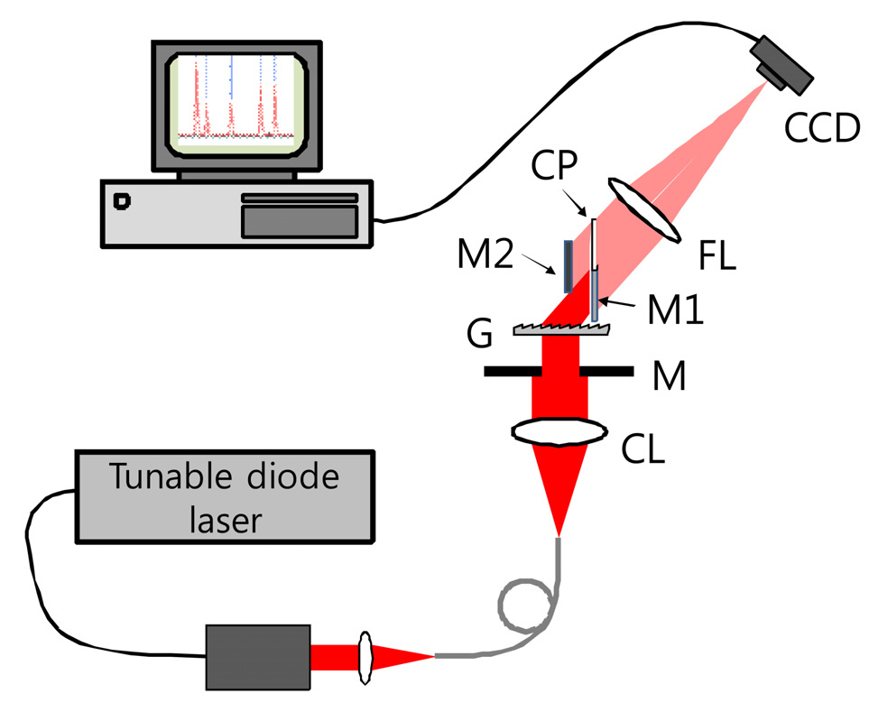
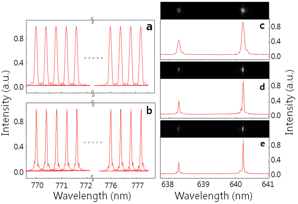
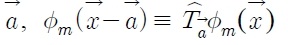
    For an experimental demonstration of the enhanced spectral resolution, an approximately 7 mm long and 5 mm wide rectangular-shaped aperture was placed onto a large diffraction grating of 1000 grooves/mm to simulate a grating of size 7 mm × 5 mm. The schematic of experimental setup is shown in Fig. 3. As a light source, a tunable diode laser operating around 773 nm with a linewidth of less than 300 kHz was coupled to a single mode fiber of NA0.12. The diverging laser beam from the output end of the fiber was collimated to make the beam size about 10 mm which was large enough to cover the entire area of the grating surface.The beam was made to strike the grating surface at a normal incidence, as in Fig. 2. Therefore, there were approximately

    mately 7000 grooves that were covered by the laser beam, meaning that the first order spectral linewidth Δλ would be 0.11 nm at 773 nm with the bare grating only. The first order diffracted beam at an angle of approximately 50.6° to the grating normal was then focused onto a chargecoupled device (CCD) camera, which was at the focal plane of a plano-convex lens of focal length 250 mm. As the laser wavelength scanned, the focal spot traversed the CCD image plane. The full width at half maximum (FWHM)of the spot corresponds to the spectral linewidth Δλ, and the enhancement of the spectral resolution is proven if the spectral linewidth is reduced in the entire tuning range of the diode laser. In Fig. 4, we present the spectral line profiles measured in the laser tuning range from 770 nm to 777.2 nm. Fig. 4(a) is the result that was obtained with the bare grating only, and Fig. 4(b) is the result with the grating and a full-half mirror pair that is depicted in Fig.2(a). The linewidths in Fig. 4(a) and 4(b) are approximately 0.11 nm and 0.06 nm, respectively. These results agree well with our expectation. The spectral resolution of the mirrorsplus-grating system is thus twice that of the bare grating case. Here, we present only a limited number of laser lines,measured every 0.4 nm for graphical demonstrations. However,for the actual measurements, we performed the experiments in a continuous scanning manner.

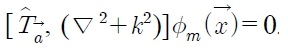
    In Fig. 4, we also present the neon emission spectra that were measured in our experiment. Due to the limited size of the CCD detection area, only two spectral lines out of many emission lines from a neon lamp are presented. One is positioned at 638.299 nm, and the other brighter line is at 640.225 nm. Fig. 4(c) corresponds to the neon spectrum that was obtained with the bare grating only, Fig. 4(d) to

    a single mirror pair with the grating, and Fig. 4(e) to double mirror pairs with the grating as depicted in Fig. 2(c).Since the relative phase between four diffracted beams is precisely adjusted, more careful alignment is necessary for the double mirror pair case. The spectral linewidths of the 640.225 nm emission for all three cases were measured as 0.095 nm, 0.049 nm, and 0.025 nm, respectively. Above each spectrum are the diffracted emission line spots that were imaged on the CCD detector. It should be noticed that along the dispersion direction the two emission spots become narrower as an additional mirror pair is added.

    From the experimental results presented so far, we found that the proposed method works well for a fairly broad range of wavelength even though the working concept is depicted only for a single wavelength in Fig. 2. It can be attributed to the following reason. In the setup, we put the half mirror as close to the grating as possible, which is less than 15 mm. Considering the dispersion of the grating 0.0015rad/nm at 773 nm, the swing angle for 7 nm wavelength change is just 0.0105 radians amounting to 0.16 mm transversal shift at the mirror. It is quite small compared to the diffracted beam width 4.6 mm and does not affect the spectral width so much. However, for a large change of wavelength, the mirror pair has to be moved vertically to be aligned for the new diffraction angle. Now we want to comment on the mirror misalignment effect on the phase mismatching. The most important part is to align the mirror pair at 90 degrees to the grating surface. If the angle is deviated from 90 degrees, then the relative phase of the two beams varies rapidly with wavelength. A simple calculation using Eq. (3) suggests that to keep the relative phase less than one quarter of from 770 nm to 777 nm the angular deviation Δθ should be less than 0.1 degree.The mirror alignment with this accuracy can be achieved by precision mechanical mounting systems without difficulty.

    IV. OPERATION PRINCIPLE IN THE GEOMETRICAL OPTICS POINT OF VIEW

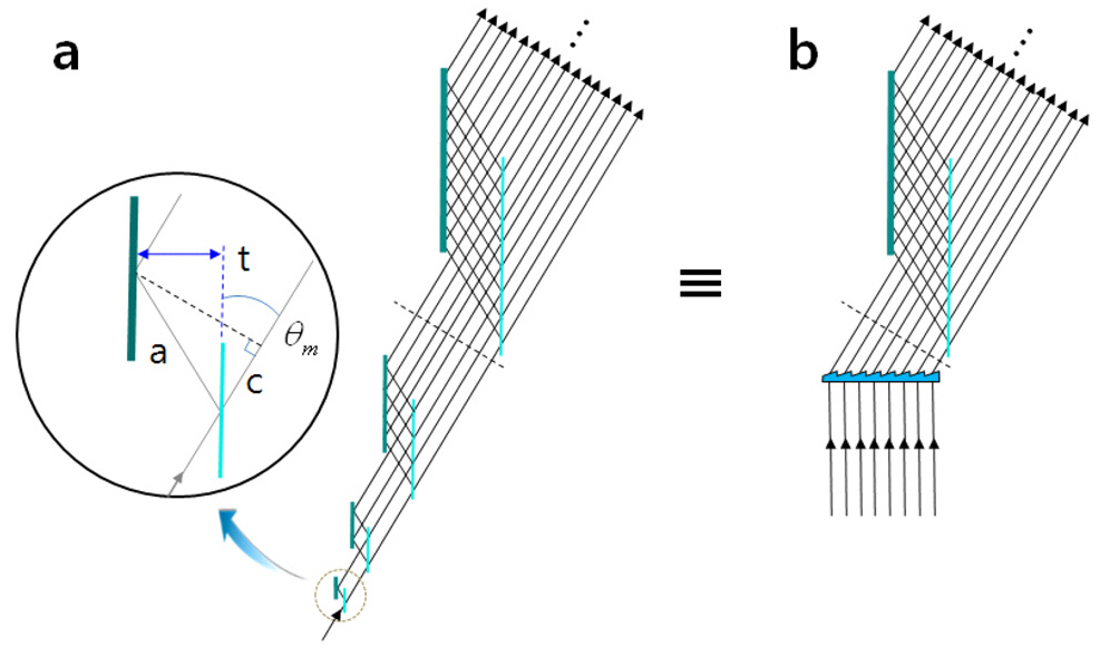
    Next, we want to look at the diffraction system from a different perspective in which the light field is represented by optical rays. This would allow us to see how the multiple two-mirror pairs in a grating system work from a geometrical optics point of view. Let’s consider the interesting optical configuration depicted in Fig. 5, which exhibits scale symmetry. Thick lines represent full mirrors and thin lines represent half mirrors. Along the light propagation direction,the mirror pair scales double in mirror size and separation,and the number of rays is also doubled accordingly. At the smallest unit enlarged in a circle, the mirror pair splits a ray into two rays, between which the optical path difference is represented by 2tsinθm. At every step where the number of rays doubles, the optical path difference between two adjacent rays remains the same as the smallest unit. It is equivalent to a diffraction grating system, which has an optical path difference of bsinθm between two adjacent grooves, where the horizontal separation t of two mirrors corresponds to half of the grating period b. The equivalence is illustrated in Fig. 5. In ray optics, the two systems in the figure work in exactly the same manner; that is, the

    diffraction angle of a specific wavelength λ should satisfy the grating equation 2tsinθm = bsinθm = . As the full-half mirror combinations can be added indefinitely in Fig. 5(a),the spectral resolution of the diffraction grating in Fig. 5(b)can also be enhanced as we wish. The scale symmetry of the optical configuration in Fig. 5(a) comes from Eq. (3), which implies that

    image

    where l is a positive integer. Although here we demonstrate this principle only for 2v (v = positive integer)rays, it can be applied to any number of rays without difficulties.Therefore, any groove number can be considered by this framework.

    For the case of non-zero incident angle upon a diffraction grating, we do not have solutions that satisfy Eq. (3) for the entire wavelength range. Instead, there is a small range, Δλ , around a specific wavelength λ0 over which the equation is satisfied. This case would be important from a practical point of view because diffraction gratings in most spectrometers are generally used in non-zero incident angles. This case will be addressed in detail in future work.

    V. CONCLUSION

    In conclusion, exploiting the translational symmetry of the diffraction gratings, we have found a way to enhance the spectral resolution beyond the limit that is set by the number of grooves covered by an incident beam. A combination of full and half mirrors that are parallel to each other can optically replicate the original grating and place a virtual grating beside it, which effectively doubles the size of the grating, resulting in the resolution enhancement. This twomirror operation can be continued indefinitely for further enhancements by adding more full-half mirror combinations despite the increased complexity and difficulty of experimental implementation. Experimental demonstrations with a narrow band tunable diode laser and a neon fluorescence lamp were provided to show its promising utilities in spectroscopy applications. We have also presented an explanation of the two-mirror operation principle from the geometrical optics point of view, and an illustration with an interesting optical configuration that has scale symmetry was provided.Even though there are some drawbacks of our method such as the limitation of the working spectral range, it can be easily applied to any grating-based spectrometer due to its simplicity. As an example, bulky spectrometer systems in which most internal parts are simply empty space can be made smaller and more compact without degrading the spectral resolution. Since the present study can be applied only to the zero-incident angle, the future study will include the oblique incident angle case for more practical applications.

참고문헌
  • 1. Savage N 2009 Spectrometer [Nature Photon] Vol.3 P.601-602 google cross ref
  • 2. Kneipp K, Wang Y, Kneipp H, Perelman L. T, Itzkan I, Dasari R. R, Feld M. S 1997 Single molecule detection usingsurface-enhanced Raman scattering [Phys. Rev. Lett.] Vol.78 P.1667-1670 google cross ref
  • 3. Nie S, Emory S. R 1997 Probing single molecules andsingle nanoparticles by surface-enhanced Raman scattering [Science] Vol.275 P.1102-1106 google cross ref
  • 4. Angelis F. D, Das G, Candeloro P, Patrini M, Galli M, Bek A, Lazzarino M, Maksymov I, Liberale C, Andreani L. C, Fabrixio E. D 2010 Nanoscale chemical mappingusing three-dimensional adiabatic compression of surfaceplasmon polaritons [Nature Nanotech] Vol.5 P.67-72 google
  • 5. Weiss S 1999 Fluorescence spectroscopy of single biomolecules [Science] Vol.283 P.1676-1683 google cross ref
  • 6. Medintz I. L, Clapp A. R, Mattoussi H, Goldman E. R, Fisher B, Mauro J. M 2003 Self-assembled nanoscale biosensorsbased on quantum dot FRET donors [Nature Mater] Vol.2 P.630-638 google cross ref
  • 7. Ebbesen T. W, Lezec H. J, Ghaemi H. F, Thio T, Wolff P. A 1998 Extraordinary optical transmission throughsub-wavelength hole arrays [Nature] Vol.391 P.667-669 google cross ref
  • 8. Dudovich N, Oron D, Silberberg Y 2002 Single-pulsecoherently controlled nonlinear Raman spectroscopy andmicroscopy [Nature] Vol.418 P.512-514 google cross ref
  • 9. Yelin D, Meshulach D, Silberberg Y 1997 Adaptive femtosecondpulse compression [Opt. Lett.] Vol.22 P.1793-1795 google cross ref
  • 10. Yamane K, Zhang Z, Oka K, Morita R, Yamashita M, Suguro A 2003 Optical pulse compression to 3.4 fs in themonocycle region by feedback phase compensation [Opt.Lett.] Vol.28 P.2258-2260 google cross ref
  • 11. Hecht E 2002 Optics google
이미지 / 테이블
  • [ FIG. 1. ]  Translation of diffracted fields by a pair of plane-parallel mirrors. (a) A grating and a few orders of diffracted fields from anincident plane wave. (b) The field translation that is induced by a pair of plane-parallel mirrors M1 and M2. The diffracted fields froma grating are reflected twice by the mirrors resulting in translated fields. The mirror pair acts as a field translator. The translation isrepresented by a vector ?. In a certain condition the translated fields can be identical to the original diffracted fields due to thesymmetry of the grating.
    Translation of diffracted fields by a pair of plane-parallel mirrors. (a) A grating and a few orders of diffracted fields from anincident plane wave. (b) The field translation that is induced by a pair of plane-parallel mirrors M1 and M2. The diffracted fields froma grating are reflected twice by the mirrors resulting in translated fields. The mirror pair acts as a field translator. The translation isrepresented by a vector ?. In a certain condition the translated fields can be identical to the original diffracted fields due to thesymmetry of the grating.
  • [ FIG. 2. ]  Diffracted fields by a grating plus plane-parallel mirrors. (a) A pair of plane-parallel mirrors the first of which is 50%reflective doubles the width of the diffracted field. (b) The field passing through the mirror pair in (a) is equivalent to a diffracted fieldfrom a two times larger grating. (c) More mirror pairs can be added to increase the effective size of the grating or the number ofgrooves. The idea clearly shows that the spectral resolution of diffraction gratings can be enhanced as desired with a limited numberof grooves.
    Diffracted fields by a grating plus plane-parallel mirrors. (a) A pair of plane-parallel mirrors the first of which is 50%reflective doubles the width of the diffracted field. (b) The field passing through the mirror pair in (a) is equivalent to a diffracted fieldfrom a two times larger grating. (c) More mirror pairs can be added to increase the effective size of the grating or the number ofgrooves. The idea clearly shows that the spectral resolution of diffraction gratings can be enhanced as desired with a limited numberof grooves.
  • [ FIG. 3. ]  Experimental setup. CL: collimation lens M:rectangular mask G: diffraction grating M1: 50% mirrorM2: 100% mirror FL: focusing lens CCD: charge coupleddevice CP: compensating plate. The compensating plate isplaced in the shifted beam path to compensate the dispersioninduced by the half mirror. It also can be used for fineadjustment of the relative phase by slight tilting.
    Experimental setup. CL: collimation lens M:rectangular mask G: diffraction grating M1: 50% mirrorM2: 100% mirror FL: focusing lens CCD: charge coupleddevice CP: compensating plate. The compensating plate isplaced in the shifted beam path to compensate the dispersioninduced by the half mirror. It also can be used for fineadjustment of the relative phase by slight tilting.
  • [ FIG. 4. ]  Reduction of the spectral linewidth over a widewavelength range. (a) The spectral line shapes of the diodelaser that are measured while scanning its output wavelength.Here the mirror pair is not added to the grating. (b) As themirror pair is added the line shapes become narrowerthroughout the entire tuning range. Each linewidth in (b) ishalf of that in (a). (c) The spectral line shapes of the neonfluorescent emission that is measured only with a grating. Nomirror pair is added. (d) A mirror pair is added to the grating.(e) Two mirror pairs are added to the grating as shown in Fig.2(c). Above each neon spectrum are the emission line spotsthat were imaged on the CCD detector. It should be noticedthat along the dispersion direction the two emission spotsbecome narrower as an additional mirror pair is added.
    Reduction of the spectral linewidth over a widewavelength range. (a) The spectral line shapes of the diodelaser that are measured while scanning its output wavelength.Here the mirror pair is not added to the grating. (b) As themirror pair is added the line shapes become narrowerthroughout the entire tuning range. Each linewidth in (b) ishalf of that in (a). (c) The spectral line shapes of the neonfluorescent emission that is measured only with a grating. Nomirror pair is added. (d) A mirror pair is added to the grating.(e) Two mirror pairs are added to the grating as shown in Fig.2(c). Above each neon spectrum are the emission line spotsthat were imaged on the CCD detector. It should be noticedthat along the dispersion direction the two emission spotsbecome narrower as an additional mirror pair is added.
  • [ FIG. 5. ]  Two-mirror operation from the geometrical opticspoint of view. Starting from a single unit of a full-half mirrorpair in (a) the optical rays are doubled at each step of thetwo-mirror operation. Both multiple two-mirror operations in(a) and a grating in (b) produce equivalent diffracted fields atthe plane that is indicated by the dashed lines. The in-phaseconditions for all of the optical rays are exactly the same forboth cases and thus so are the dispersions.
    Two-mirror operation from the geometrical opticspoint of view. Starting from a single unit of a full-half mirrorpair in (a) the optical rays are doubled at each step of thetwo-mirror operation. Both multiple two-mirror operations in(a) and a grating in (b) produce equivalent diffracted fields atthe plane that is indicated by the dashed lines. The in-phaseconditions for all of the optical rays are exactly the same forboth cases and thus so are the dispersions.
(우)06579 서울시 서초구 반포대로 201(반포동)
Tel. 02-537-6389 | Fax. 02-590-0571 | 문의 : oak2014@korea.kr
Copyright(c) National Library of Korea. All rights reserved.