Since laminated carbon fiber reinforced polymer (CFRP)composites have high specific strength and stiffness, they can be effectively used to reduce the weights of aeronautical structural components. Laminated CFRP is made from unidirectional prepreg or a woven fabric sheet. The laminated composite structures used in aerospace engineering require the design of the stacking sequence as well as the design of dimensions because the mechanical properties of the laminated components strongly depend on the stacking sequence of the laminates. Many aircraft composite structures are designed using the building block approach of MIL-Handbook-17. The building block approach requires a large number of experiments, which limits the available fiber orientations to a small set of 0°, 45°, ?45° and 90° to prevent high experimental cost. Therefore, optimization of the stacking sequence is combinatorial optimization with a limited number of available fiber angles.
It is difficult to detect internal damage to a laminated CFRP structure such as delamination or matrix cracking because such damage is not visible at the exterior of the structure. The inability to inspect CFRP structures visually demands the development of automatic monitoring or damage-detection systems. Although fiber optic sensors are good candidates as damage-monitoring sensors, they require further research before they can be considered to be effective. Carbon fiber is an excellent electrical conductor and has been used as a strain sensor for decades. One possible damage/strain sensing method for CFRP composites is self-sensing using carbon fibers as sensors.
In the present study, the self-sensing of CFRP composites and the structural optimization of CFRP components in Japan are reviewed. Recent research on self-sensing has achieved identification of the damage location and dimensions through measurement of changes in the electrical resistance at multiple points within target CFRP structures. This paper reviews some of the significant research to have been carried out in Japan. The optimization of composites is then reviewed to provide clear solutions to problems of design methods of laminated CFRP; i.e., simultaneous optimizations of stacking sequences and dimensions of stiffened panels.
2. Self-Sensing CFRP Composites
Carbon fiber is an electrically conductive material. Even in the direction transverse to the fiber direction, electric current flows because of fiber contact. Delamination cracks and matrix cracking of CFRP composites can be detected through measurements of changes in the electrical resistance. This damage detection technique does not require additional sensors; the reinforcement carbon fibers are used as sensors.Hence, the method of measuring the electrical resistance change of CFRP composites is referred to as a self-sensing method.
Self-sensing CFRP is a multifunctional composite. The present review presents research on self-sensing CFRP in Japan.
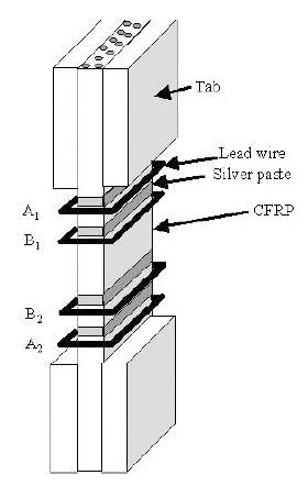
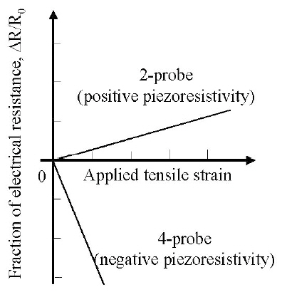
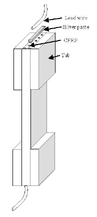
Employing a two-probe method, Schulte and Baron (1989)reported that the electrical resistance of a CFRP laminate in the fiber direction increases as the tensile load applied in the fiber direction increases. The two-probe method applies two electrodes to measure the electrical resistance as shown in Fig. 1 Other researchers also reported this positive piezoresistance (a positive gage factor) (Ceysson et al., 1996;Irving and Thiagarajan, 1998; Muto et al., 1993; Xu et al.,1996).
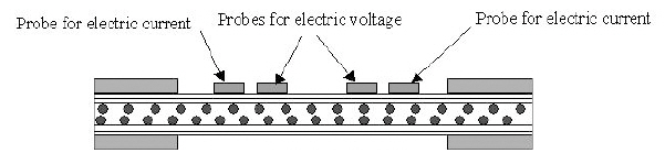
Wang and Chung (2000) obtained contrary results. They employed a four-probe method to measure the precise change in electrical resistance in the fiber direction during tensile loading in the fiber direction of a CFRP laminate as shown in Fig 2Their results showed negative piezoresistance(a negative gage factor.) The electrical resistance in the fiber direction decreases with an increase in the tensile load applied in the fiber direction (see Fig.3 ). The four-probe
method uses an outer pair of electrodes to apply electric current and an inner pair of electrodes to measure the resistance from the voltage drop between the pairs.
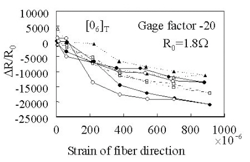
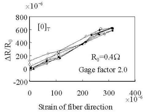
On the other hand, Ogi and Takao (2005) experimentally showed positive piezoresistivity of unidirectional CFRP using the four-probe method. They presented a significant model of the piezoresistivity of unidirectional CFRP. Todoroki and Yoshida (2004) also revealed experimentally that the unidirectional CFRP has positive piezoresistivity using the four-probe method. In the experiments (Todoroki and Yoshida, 2004), negative piezoresistivity was obtained before removing the surface resin without polishing the surface. In a test using an identical specimen, the surface was polished and positive piezoresistivity was obtained. The results are shown in Figs. 4 and 5. In these figures, the abscissa is the applied tensile strain and the ordinate is the ratio of electrical resistance change. The figures show that electrical contact at the electrodes affects the resistance change. Angelidis et al. (2004) and Todoroki and Yoshida (2005) showed that the electrical contact at the electric-current electrodes affects the measurement of the electrical resistance of CFRP.
Even if we use the four-probe method, the strongly orthotropic conductivity of CFRP causes a problem of electrical contact at the electrodes where applying electric current. In the case of the self-sensing CFRP, electrical contact at the electrodes is quite significant even if we use the four-probe method. A method using electrodes made of electrical copper plating is presented in the other paper along with tests results of durability (Todoroki et al., 2010c).
2.3 Monitoring of fiber breakages and matrix cracking
Self-sensing methods have been applied to fatigue damage detection by several researchers (Muto et al., 1993;Seo and Lee, 1999). All applied processes are similar to the monotonic tensile test to measure the change in electrical resistance in CFRP specimens. These tests were applied to unidirectional CFRP and cross-ply CFRP laminates. The electrical resistance increased with a decrease in specimen stiffness. The increase in the electrical resistance of the unidirectional CFRP indicates that the self-sensing method
detects fiber breakages.
Park et al. (2001) and Xia et al. (2003) proposed an interesting model of carbon fiber networks to simulate the gradual increase in the electrical resistance of CFRP under tensile loading. They modeled the CFRP as a network of resistances and found several required properties of the model through comparison with experimental data.
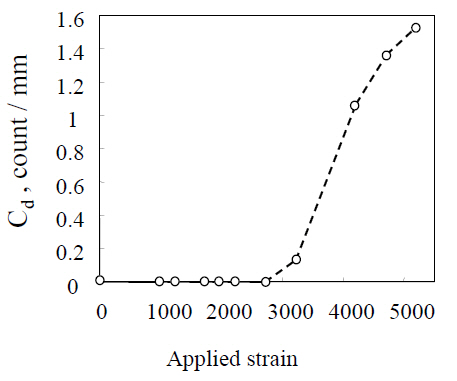
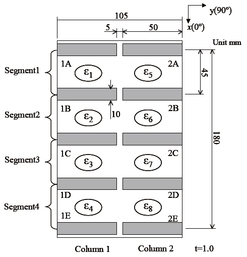
Omagari et al. (2005), Todoroki and Omagari (2008), and Todoroki et al. (2006a, b) showed that the four-probe method is applicable to the monitoring of matrix cracking in crossply CFRP laminates. In their tests, four probes were placed on a single surface of a beam specimen as shown in Fig. 6.
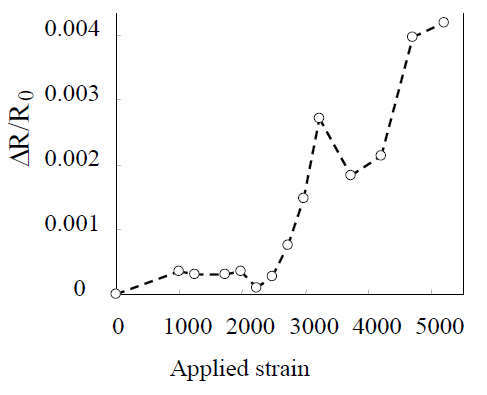
Tensile tests were then performed to measure the density of matrix cracks; the measured density is shown in Fig. 7 The electrical resistance measured under a completely unloading condition is shown in Fig. 8 The experimental results reveal that electrical resistance increased with matrix cracking.Even after complete unloading, specimens with matrix cracks retained a residual increase in electrical resistance. The effect of specimen thickness on the residual electrical resistance increase was also investigated. When 90° ply is thicker than 0° ply, the effect of residual stress relief is smaller, and this causes the crack surface contact. Therefore, the slope of the plot of the fraction of the electrical resistance change versus reloading during reloading has been considered.The method was also employed to investigate damage at cryogenic temperatures (Todoroki et al., 2006b) and found to work well in detecting the initiation of damage even at such temperatures.
2.4 Monitoring of delamination
The self-sensing method based on the change in electrical resistance has been applied in monitoring delamination cracking. Since electrical resistance changes due to delamination cracking are very small, Hirano and Todoroki(2007), Todoroki (2001), Todoroki et al. (2002a, b, 2003, 2004a,b, 2005, 2010a, b), Todoroki and Suzuki (2000), Todoroki and Tanaka (2002), Ueda and Todoroki (2006, 2008), and Ueda et al. (2004, 2005) applied an electrical bridge circuit or modified amplifiers to obtain large output signals from the delamination events. The modified bridge circuit is schematically shown in Fig. 9 Since this only differs from the bridge circuit in a conventional strain gage by a connected electrical resistance, a conventional strain amplifier can be directly applied without modification of the circuit. Moreover,as for conventional strain gages, temperature compensation is possible using a dummy specimen.
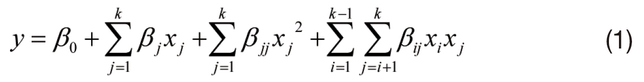
In the monitoring, Hirano and Todoroki (2007), Todoroki(2001), Todoroki and Suzuki (2000), Todoroki et al. (2002a,b, 2003, 2004a, b, 2005), Todoroki and Tanaka (2002), Ueda and Todoroki (2006, 2008), and Ueda et al. (2004, 2005) used response surfaces to obtain the relationship between the electrical resistance changes and delamination location or dimensions. Quadratic polynomials were adopted because of their simplicity. The response surface can be described with quadratic polynomials as follows.
Although the method requires a large number of experiments, it does not demand modeling. Instead of the experiments, finite-element method (FEM) analyses can be carried out to obtain electrical resistance changes due to delamination cracking (Todoroki et al., 2010a, b).
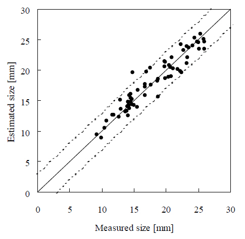
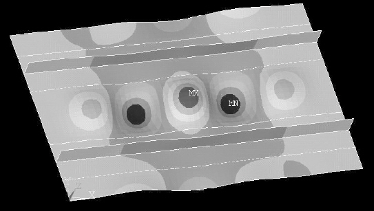
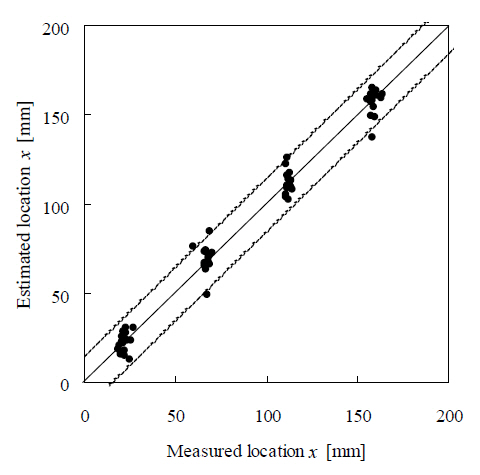
The method based on the change in electrical resistance has also been applied to plate-type specimens (Todoroki et al.,2002b). An example of the configuration of these specimens is shown in Fig. 10 In this example, 10 electrodes were cocured onto the plate to measure changes in the electrical resistance (copper plating can be used for existing structures).Delamination was achieved by indentation loading with a cylindrical jig. The delamination location and dimensions were estimated on the basis of the response surface. The delamination was estimated for both cross-ply and quasiisotrolaminates. Figure 11 shows the typical estimation results for the delamination location (
The abscissa is the measured maximum size of delamination and the ordinate is the estimated results. The estimates of the delamination size and location were quite accurate as shown in the figures. In estimating the delamination location and size, the estimation results for the quasi-isotropic laminate were also very good when normalized electrical resistance changes were used (Todoroki et al., 2003).
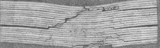
The estimation method requires a large number of experiments to make the response surfaces. FEM analyses allow the number of experiments to be reduced for thin CFRP laminates (Todoroki et al., 2010b). However, delamination decreases the electrical resistance of thick CFRP laminates(Todoroki et al., 2010a) but increases the electrical resistance of a thin CFRP laminate (Todoroki et al., 2010b). For thick CFRP laminates, delamination results in a dent as shown in Fig. 13,which decreases the electrical resistance of a thick CFRP laminate.
The durability of electrodes was tested by Todoroki et al.(2010c). The self-sensing method has also been applied to detect compression damage such as fiber microbuckling(Todoroki et al., 2010d). In addition, bolted joint damage has been monitored employing the method (Shimamura et al.,2006).
3. Structural Optimization of Laminated Composites
The use of laminated composite structures in aerospace engineering requires the design of the stacking sequence as well as the dimensions because the mechanical properties of the laminated components strongly depend on the stacking sequences of the laminates. Many aircraft composite structures are designed using the building block approach of MIL-Handbook-17. The building block approach requires a large number of experiments, and this limits the available fiber orientations to a small set of 0°, 45°, ?45° and 90°to prevent high experimental cost. Hence, the stacking sequence optimization is a combinatorial optimization with limited fiber angles as previously mentioned.
For the stacking sequence optimizations, Miki (1985)and Fukunaga and Chou (1988) proposed a graphical optimization method employing lamination parameters.Genetic algorithms are widely used to optimize the stacking sequence (Cho and Rhee, 2003; Kogiso et al.,1994; Le Riche and Haftka, 1993; Liu et al., 2000; Marcelin et al., 1995; Todoroki and Haftka, 1998; Todoroki and Sasai,1999; Todoroki et al., 1995; Zako et al., 1997). Narita (2003)proposed a layer-wise optimization method, which has the lowest computational cost.
Terada et al. (2001) and Todoroki and Terada (2004)published a new deterministic method for the optimization of the stacking sequence of composite laminates, named the fractal branch and bound (FBB) method. The FBB method has been applied to maximization problems of buckling load(Terada et al., 2001; Todoroki and Terada, 2004). The FBB method has also been applied to maximization problems of the flutter speed of a laminated composite wing that has multiple local maxima (Hirano and Todoroki, 2004, 2005). The FBB method has been extended to the simultaneous optimization of the stacking sequence of multiple laminates,such as laminates of a stiffened panel (Sekishiro and Todoroki,2006; Todoroki and Sekishiro, 2007), and to asymmetrical laminates (Matsuzaki and Todoroki, 2007).
In optimizing composite structures, Yamazaki (1996)employed a well-known mathematical programming method for stiffened composite components with lamination parameters. The lamination parameters are considered as independent design variables in the first stage. In the second stage, practical stacking sequences that have lamination parameters similar to those of the optimal sets are searched using a genetic algorithm.
The present review focuses on the modified efficient global optimization method (Todoroki and Sekishiro, 2008a,b) using the FBB and multi-objective genetic algorithm(MOGA). The method optimizes the stacking sequences and dimensions of a stiffened composite panel simultaneously.The FBB for multiple laminates is integrated in the new method as a lower-layer optimization.
In-plane stiffness terms of symmetric laminates are represented with in-plane lamination parameters
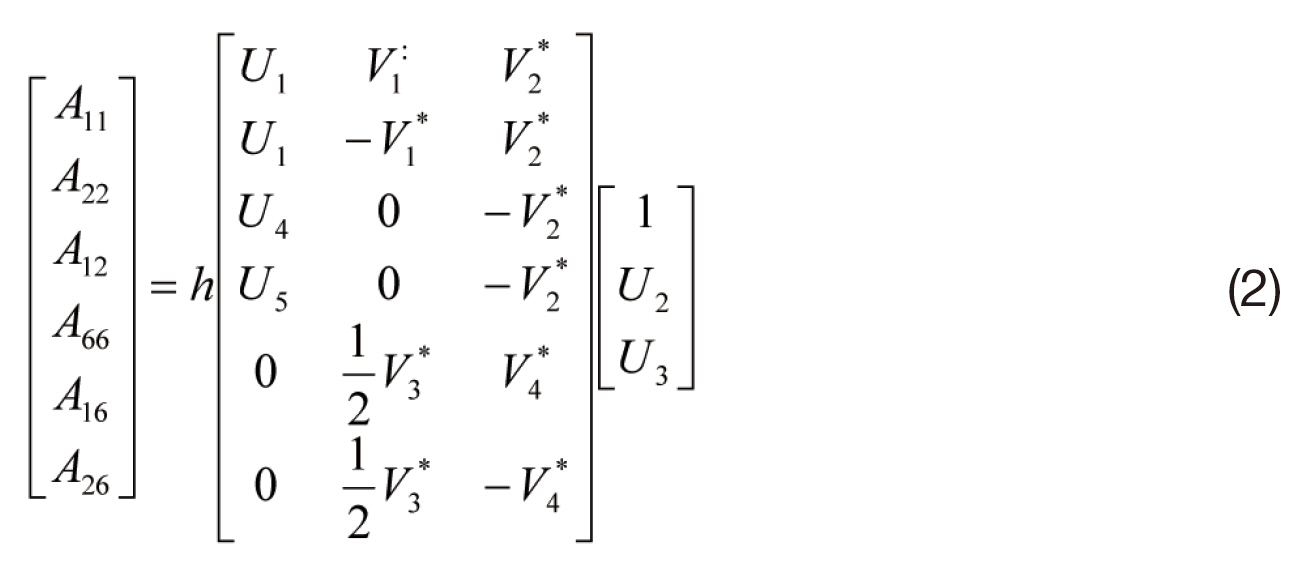
Here h is the thickness of the laminate,
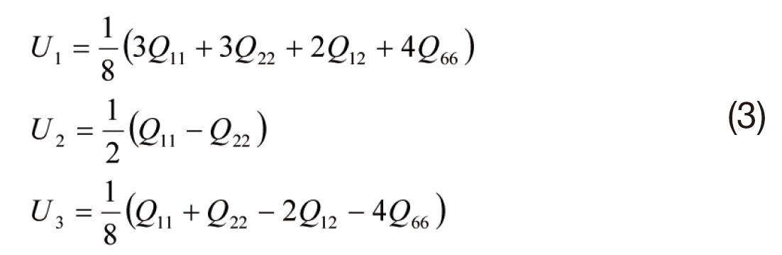
Here,

where
The in-plane lamination parameters are as follows.
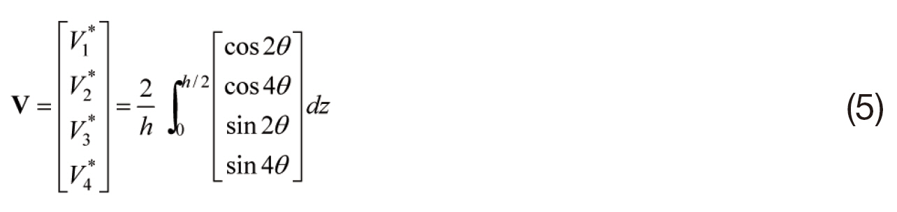
Here
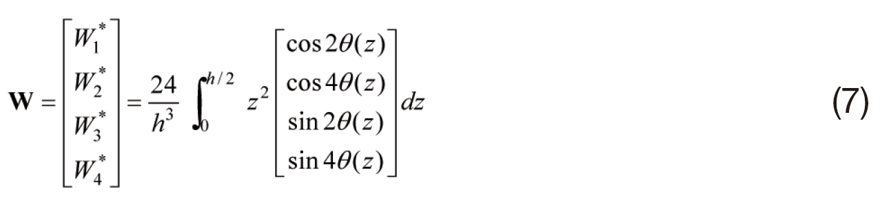
The out-of-plane stiffness terms of the laminates are represented with out-of-plane lamination parameters
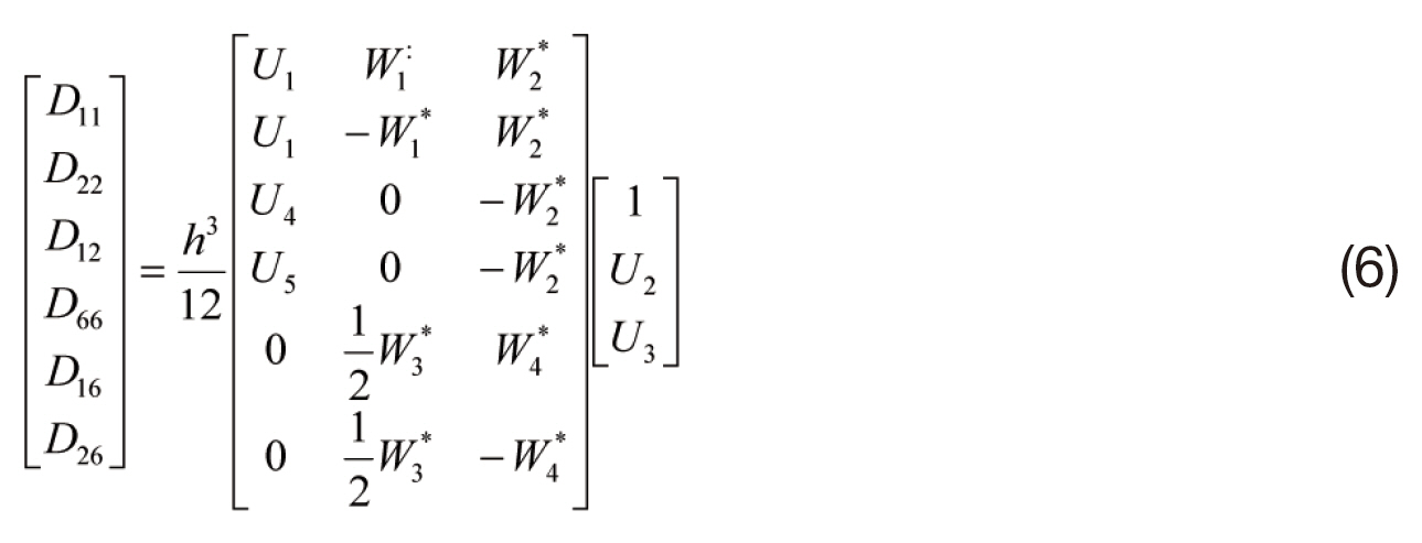
The out-of-plane lamination parameters are defined as follows.
Plots of all feasible laminates in the lamination parameter space are fractal images when the fiber angles are limited to small sets (Todoroki and Terada, 2004). The FBB method uses the branch-and-bound method to prune the inferior branches using a surrogate model of a quadratic response surface.
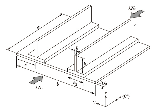
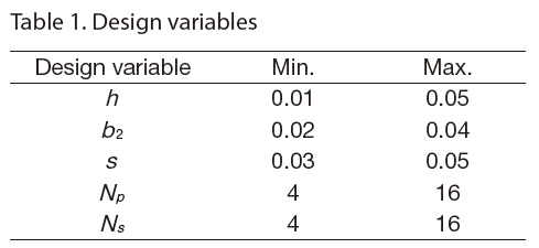
The optimization target is a blade-stiffened composite panel as shown in Fig. 14The design variables of the stiffener are a height of the stiffener of
The buckling load is defined as the ratio (λ of the buckling load to the single-compression load along the
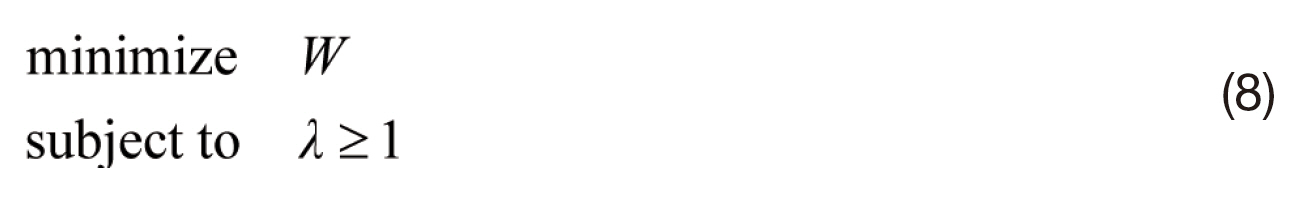
The total weight of the blade-stiffened panel is easily calculated as follows.
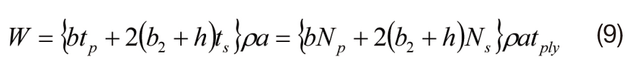
Here
In Eq. (8), the first constraint means that the buckling load must be greater than 15,000 kN/m. The available range of each design variable is given in Table 1.
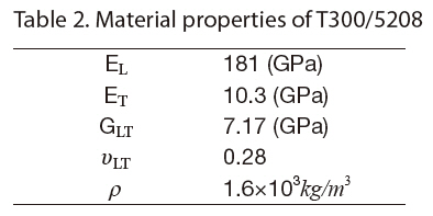
The material used here is carbon-fiber-reinforced epoxy composite T300/5208. The material properties are presented in Table 2 The composite panel and blade-stiffener are symmetric laminates, and the available fiber angles are limited to a small set of four angles: 0°, ±45° and 90°. In the case of the fiber angles, there is a balance rule for the ply angles and a four-contiguous-ply rule to prevent large matrix cracking; i.e., no more than four plies with the same fiber angle can be stacked contiguously.
3.4 Optimization using the MOGA
The objective function of the optimization problem (Eq.[8]) is simple and easily calculated when all dimensions of the stiffened panel are given. However, determination of the buckling load constraint has large computational cost because it requires FEM analysis in each evaluation of the buckling load. Here, the objective function of Eq. (8) is directly used without the surrogate model. On the other hand, the constraint of the buckling load ratio is approximated using a Kriging model to reduce the computational cost. As the variables of the response surface, all dimensions of the blade-
stiffened panel and the lamination parameters of both panel and stiffener are adopted here. Since automatic construction of a Kriging model is useful, the design and analysis of computer experiments (DACE) model is employed (Welch et al., 1992).
The Kriging mode enables us to calculate the estimator of the standard deviation, and the value is used to calculate the estimation error. For the DACE model, the estimation errors at the sampling points are zero, and the estimation error becomes large when the estimation point is far from the adjacent sampling points.
Latin hypercube sampling (LHS) experiments are adopted here (Welch et al., 1992). LHS gives uniformly distributed sampling in the entire design space. However, LHS is not simple for composite structures because lamination parameters (Fukunaga and Chou, 1988; Miki, 1985) are not independent variables. To solve this problem, we prepared all feasible symmetric laminates of 16 plies (i.e., the half ply number is eight). The total number of feasible plies that satisfy the balancing rule is 3281. From this set of feasible laminates, a set of laminates (the number of laminates is
To select candidate points for variables of dimensions,all variables are divided into
The multi-objective genetic algorithm (MOGA) has already been published in a well-known textbook (Deb, 2001). Since
Design variables
[Table 2.] Material properties of T300/5208

Material properties of T300/5208
the MOGA is similar to a simple genetic algorithm, a detailed explanation is not given here.
The present method employs two-layer optimization. In the upper layer, the structural dimensions are optimized using the MOGA. Chromosomes of each individual correspond to structural dimensions such as the height or width of the stiffener, and these dimensions are sufficient information for evaluating the structural weight. To evaluate the buckling load, however, the stacking sequence of the composite laminates must be known. The upper-layer optimization activates a lower-layer optimization of the stacking sequence. The stacking sequence of the stiffener and panel are optimized employing the modified FBB method; this is a modified version of the FBB method that optimizes more than two laminates simultaneously. These optimization processes are described as follows.
(1) The experiments are designed using the LHS to select
(2) Initial individuals of the MOGA (total population of 100) are determined using random numbers.
(3) Upper-layer optimization is performed using the MOGA.
(a) The fitness of each individual is evaluated; lowerlayer optimization is performed to optimize the stacking sequence of the stiffener and panel using the extended FBB method.
(b) Non-dominated individuals are searched using two objective functions: weight reduction relative to the provisional structure and the probability of satisfaction of the buckling load.
(c) The diversity of the population is evaluated for all individuals, and the fitness value of each individual is calculated.
(d) Selection is performed using a Parate-ranking method, and mutation conducted after crossover of the selected individuals.
(4) The MOGA is terminated after the 300th generation.
(5) The top 10 individuals of the probability of satisfaction of the buckling load are calculated employing FEM analyses with consideration of the diversity of the population in the 100 Parate solutions.
The 10 new FEM results are added to the Kriging model dataset. The process cycles from step (2).
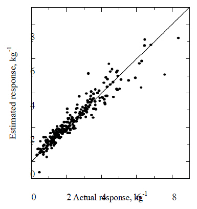
A total of 251 points were selected in the LHS experiments,and FEM analyses were conducted at the selected sampling points. Cross-validations of the Kriging model were performed at all points, and the results are shown in Fig. 15.The cross-validation is the checking method of the Kriging model; a Kriging model is calculated from a set of sampling data except for a selected point, and the selected point is estimated with the calculated Kriging model. Afterward,the Kriging model is estimated at the selected point. Thus,all data shown in Fig. 15 are the new data for the Kriging model. The abscissa is the true value and the ordinate is the estimated value. Good estimations are plotted on the diagonal line. Figure 15 shows that the Kriging model almost always provides good estimations.
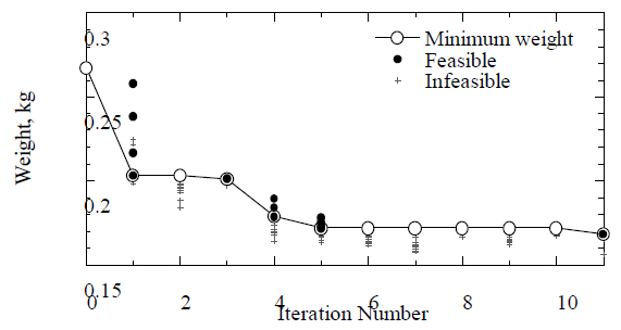
Using this Kriging model, the optimizations of the MOGA are cycled 10 times; 50 extra FEM analyses were added to the Kriging model for accuracy. Figure 16 shows the results of the minimum-weight history of the MOGA. The result at zero cycles is the provisional optimal structure. As shown in Fig. 16,the Parate solutions obtained from the MOGA always include solutions that have a high probability of satisfying the constraint of the buckling load.

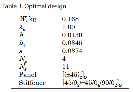
Optimal design
Table 3 gives the optimal solution obtained after five cycles of optimizations of the MOGA. In the optimizations of the MOGA, there were 361 FEM analyses. The obtained minimum weight is 0.168 kg. Figure 17 shows the buckling of the optimal designs. The result without optimization of the stacking sequence is 0.238 kg using fixed stacking sequences of quasi-isotropic laminates and the dimensions were selected as design variables in this case. The result obtained from the MOGA is 38% lighter than the result obtained without optimization of the stacking sequence.
The MOGA with the Kriging approximation and FBB method is adopted in the optimization of the dimensions of the stiffened panel and stacking sequences. Since the weight is easily calculated, only the constraint of the buckling load is approximated using a Kriging model named the DACE model. The new method is applied to a blade-stiffened panel to obtain the minimum-weight structure under a constraint of the buckling load. The results obtained show that the method provides a practically optimal result with relatively few FEM analyses
The present review covers the self-sensing and structural optimization of laminated carbon composites in Japan.The author’s group has mainly researched these two areas. Self-sensing is one of the multiple functions of such composites. The self-sensing method has recently become popular because it does not require additional sensors. The present review presents recent advances in self-sensing in the author’s laboratory and a structural optimization method that optimizes the stacking sequence of laminated composites?a modified efficient global optimization method employing the MOGA. The review also presents the process of optimization and an optimization example of a blade-stiffened composite panel. The method significantly reduces the number of analyses required and provides a practical optimal result for reducing the weights of aerospace structural components.