Nanomaterials are attractive materials due to the fact that nanofiller reinforced composite can achieve the highest efficiency of reinforcement, super mechanical properties as well as other physical properties such as thermal properties, barrier properties, electrical properties, etc. [1]. Since 1980, when the first clay nanocomposite was synthesized, many researchers have focused on nanocomposites with different nanofillers. Graphite could be a good candidate as reinforcement for polymers since it is a layer structured material that has the highest modulus. One of the key factors is how to effectively exfoliate graphite into nanoplatelets. Recent research by Drzal at Michigan State University has shown that it is feasible to exfoliate natural graphite into nanoplatelets having thicknesses of less than 10 nm and diameters ranging to tens of microns in size [2,3]. These nanoparticles are called “exfoliated graphite nanoplatelets” (xGnP). An important factor in producing xGnP is its low cost estimated to be less than $20 per kg which is about 100 times less expensive than carbon nanotubes [4]. This makes xGnP reinforced polymer nanocomposite manufacture products very feasible. xGnP has been incorporated into polymers such as epoxy, vinyl ester, polyamide, polypropylene, and polylactic acid for improving the mechanical and electrical properties [5-8]. It is found that xGnP not only improves the electrical conductivity of the host polymer, but also produces nucleation effects for thermoplastics. In addition, xGnP can also be used as a component in energy storage, fuel cells, solar cells, sensors, biosensors and batteries [9]. Thus, xGnP is a versatile material that can act as a multifunctional additive for potential applications.
Nanocomposites can be made during the polymerization of a monomer since it can be inserted into the gallery of clay through interaction and exfoliation [10]. In addition, thermoplastic nanocomposites can also be made through the melt compounding method [11]. This requires using plastic processing equipment such as extruder, brabender mixer, and injection molder for compounding and molding of nanofillers with polymer matrices. Physical properties of nanocomposites are dependent on the dispersion of the nanoparticle in the matrix, which mainly depend on compatibility between filler and matrix and also depend on the processing parameters [12]. In extrusion, there are several factors that control the dispersion of nanoparticles in thermoplastic nanocomposites such as screw configuration, rotation of speed, use of coupling agent, chemistry of matrix and filler, feeding rate, shear intensity, residence time, and so on [13-16].
In this project, xGnP was incorporated into nylon 6 (PA6) through the melt compounding method to form a nanocomposite. The flexural properties, electrical resistivity,morphology, and structure of the nanocomposite were measured and characterized. The influence of processing on morphology and properties of xGnP/PA6 nanocomposite was determined.
15 micro-size exfoliated graphite nanoplatelets (xGnP-15)were made at the Composite Materials and Structures Center at Michigan State University according to the reported method [4-6]. Polyamide 6 (Durethan B40SK Extrusion Grade) was received from Bayer.
3.1. Nanocomposite preparation
A DSM Micro 15 cm3 Compounder (vertical, twin-screw microextruder) was used to mix xGnP-15 and PA6 to get a nanocomposite specimen. Prior to mixing, PA6 and xGnP-15 were vacuum-dried at 80℃ overnight. The mixture of xGnP-
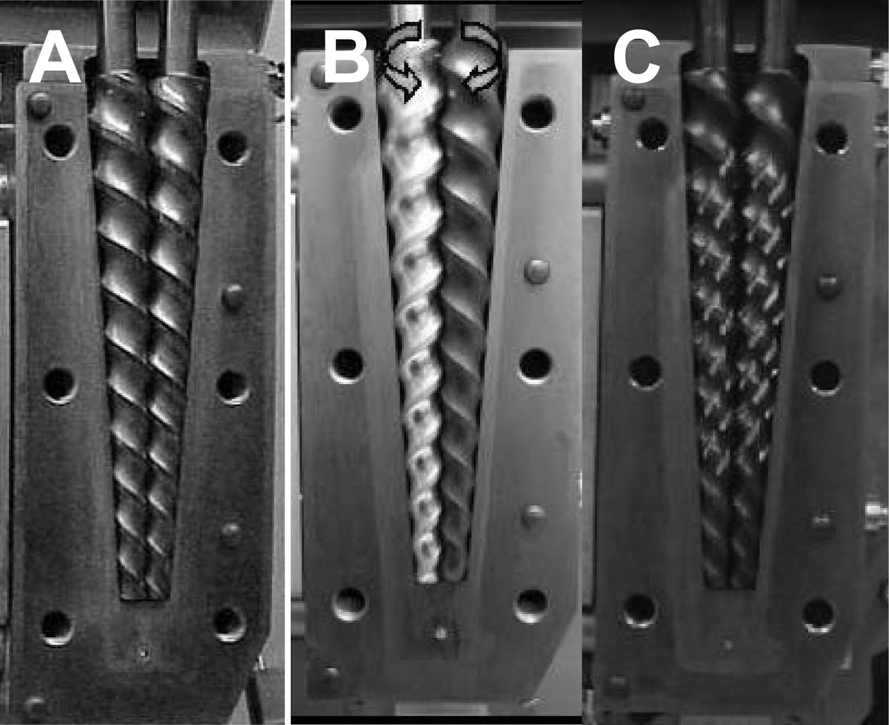
15 and PA6 was processed at 260℃ for 3 min at a screw speed of 100 rpm. The melt mixed mixture was then transferred to a Daca Micro Injector operating at Tbarrel = 260℃ and Tmold = 80℃. Three types of twin-screw were used, namely co-rotation (CoR) twin screw, counter rotation (CNR) twin-screw, and modified co-rotation (MCoR) twin-screw as shown in Fig. 1.
The flexural properties of xGnP reinforced PA6 nanocomposites were measured with a United Testing System SFM-20 according to ASTM D790. System control and data analysis were performed using Datum software.
The electrochemical AC impedance spectrum over a range of frequencies of these xGnP reinforced nanocomposites was measured with a Gamry instrument under FAS2M Femtostat plug system and potentiostatic mode. Equation (1) can be used to calculate the resistivity of the sample.
Where I is the impedance value at 1 Hz, R is the resistivity, S is the intercept surface area, and T is the thickness of the sample.
The morphology of xGnP reinforced PA6 nanocomposites was observed with a Phillips Electroscan 2020 Environmental Scanning Electron Microscope (ESEM) with an accelerating voltage of 20 kV to check the dispersion of xGnP in PA6. The cryo-fractured surface of xGnP reinforced PA6 nanocomposites was prepared with liquid nitrogen.
3.5. Wide angle X-ray diffraction
Wide angle X-ray diffraction spectrum of xGnP reinforced PA6 nanocomposites were performed with using a Rigaku 200B X-ray diffractionmeter system equipped with Cu KR radiation with λ=0.541 nm that has a monochrometer operating at 45 kV at room temperature. The step size was 0.05 and a scan rate was 6°/min. The scan range was from 2° to 34°.
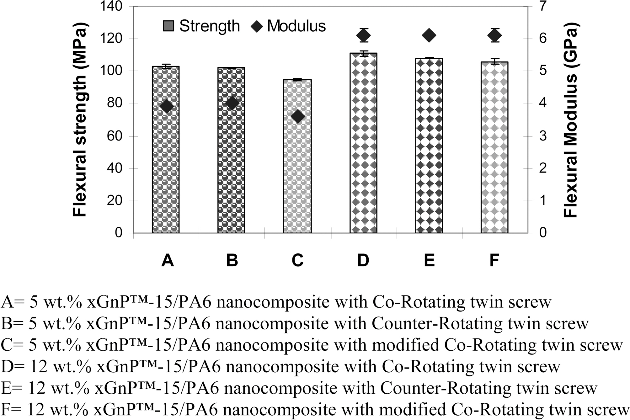
The flexural properties of xGnP-15 reinforced PA6 nanocomposites are shown in Fig. 2. It was found that the
5 wt.% xGnP-15 reinforced PA6 nanocomposite processed with CoR twin screw had the same flexural modulus and strength as the one processed with CNR twin screw, but higher than the one processed with MCoR. Similarly, the 12 wt.% xGnP-15 reinforced PA6 nanocomposite processed with CoR had similar flexural strength and modulus as the one processed with CNR as well as MCoR. This means that changing the twin screw direction of rotation had no impact on the flexural strength and modulus of the final PA6 nanocomposite.
The rule of mixture (ROM) is applied to predict the modulus of the nanofiller reinforced nanocomposites. Here, equation (2) is used to depict the modulus results of xGnP reinforced polyamide 6 nanocomposites.

Where Ec is the modulus of nanocomposite, K is the filler efficiency factor of the nanocomposite modulus, Ef is the modulus of filler, Vf is the volume fraction of filler, Em is the modulus of matrix, and Vm is the volume fraction matrix.Equation (3) was used to calculate the volume fraction of the filler.
Where Vi, Wi, and ρi are the volume fraction, weight fraction and density of component i in the nanocomposites.
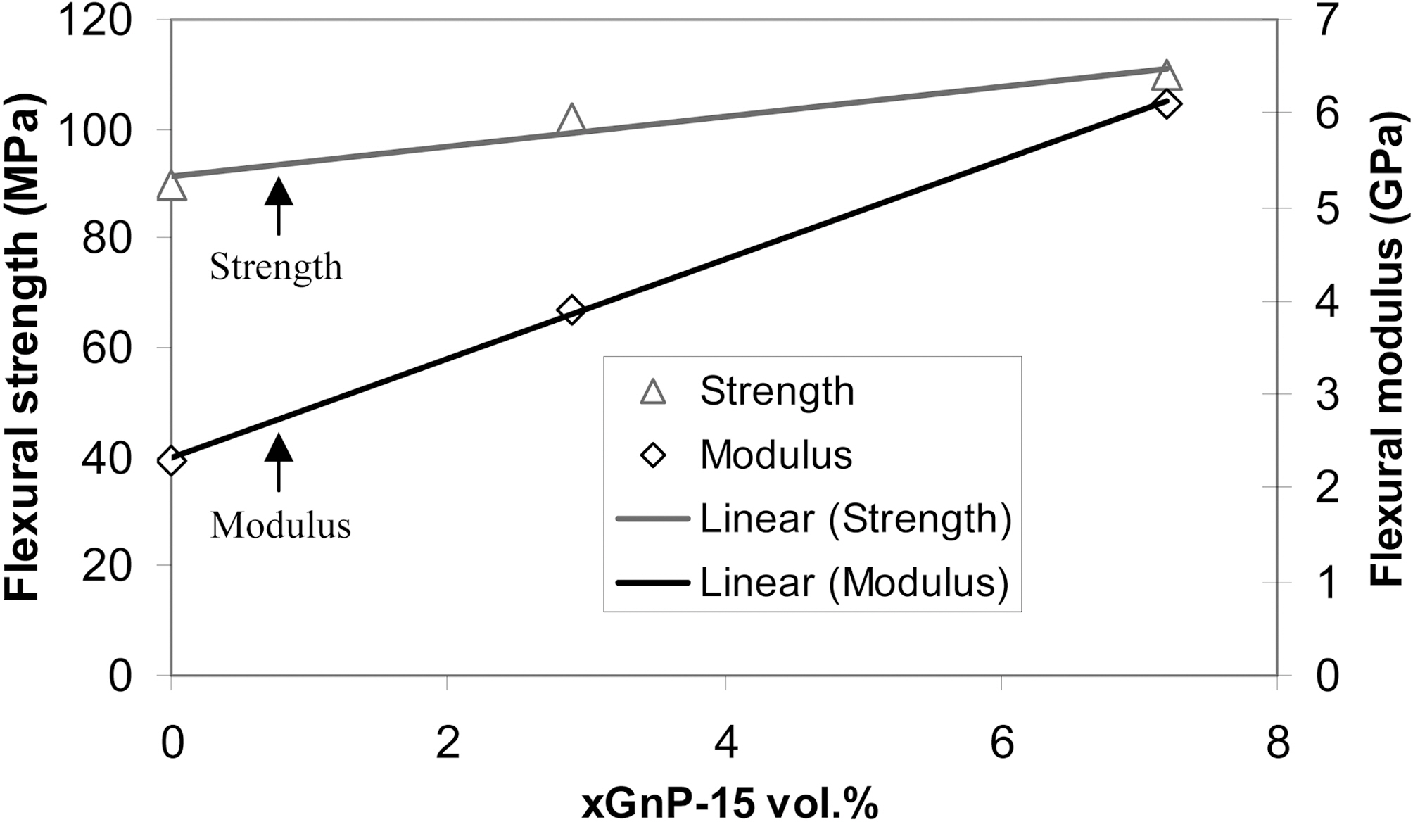
The plots of the CNR processed nanocomposite modulus and strength vs. volume fraction of xGnP-15 in the nanocomposites is shown in Fig. 3. It was found that the flexural modulus of xGnP-15 reinforced PA6 nanocomposite increased with increases in volume fraction of xGnP-15. Only 7 vol.% xGnP-15 can improve the modulus of PA6 about 270%. Therefore, it can be concluded that xGnP-15 is a very promising reinforcement material for improving the modulus of the reinforced PA6 nanocomposite. However, the flexural
strength of xGnP-15 reinforced PA6 nanocomposite only slightly increased with increasing the content of xGnP-15. This is due to the fact that xGnP-15 is has a relatively large size.
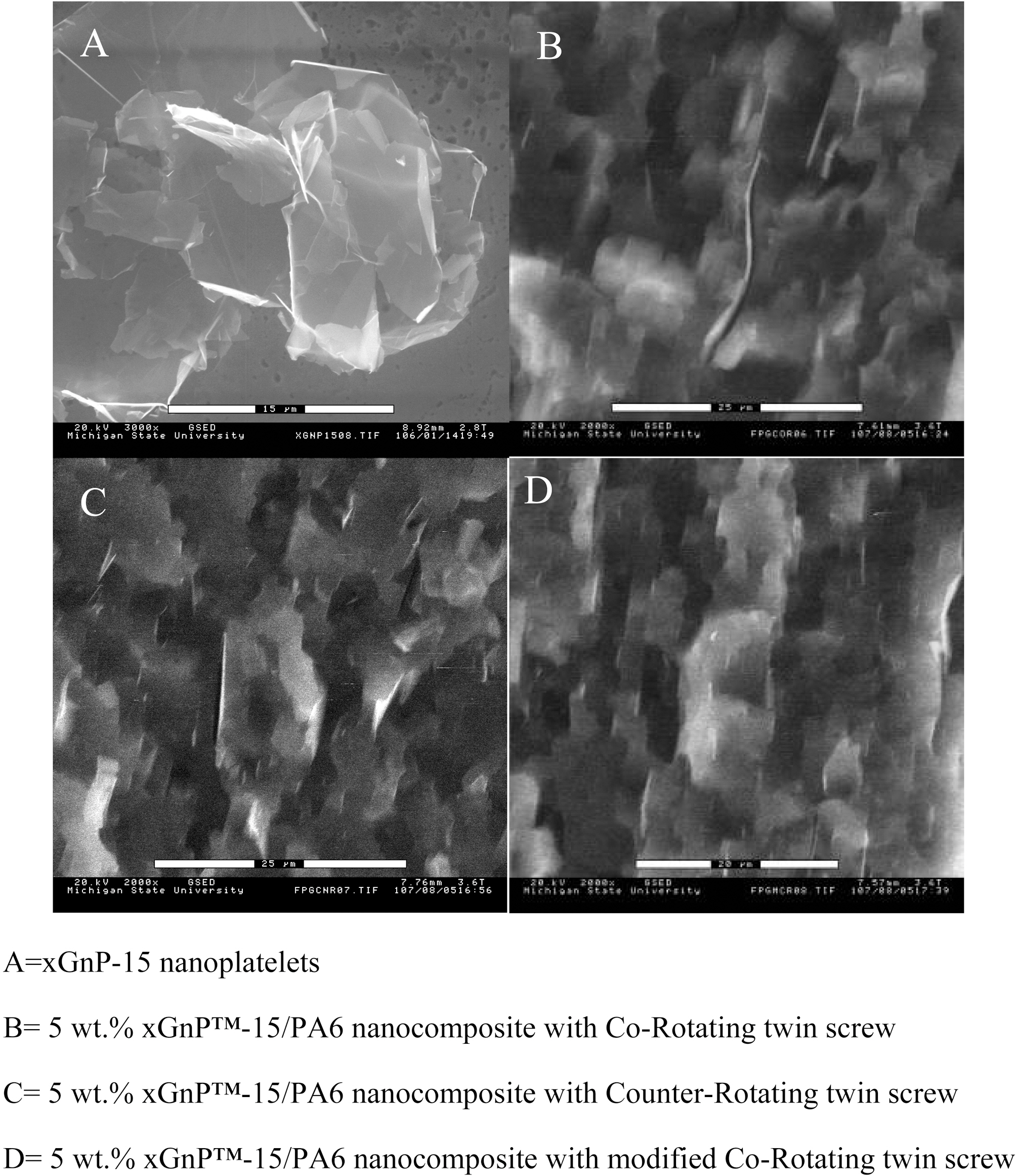
The ESEM morphology of 5 wt.% xGnP-15 reinforced PA6 nanocomposite is shown in Fig. 4. It was found that the xGnP-15 nanoplatelets have a size was around 15 ㎛ as shown in Fig. 4a. The xGnP nanoplatelet is clearly seen in
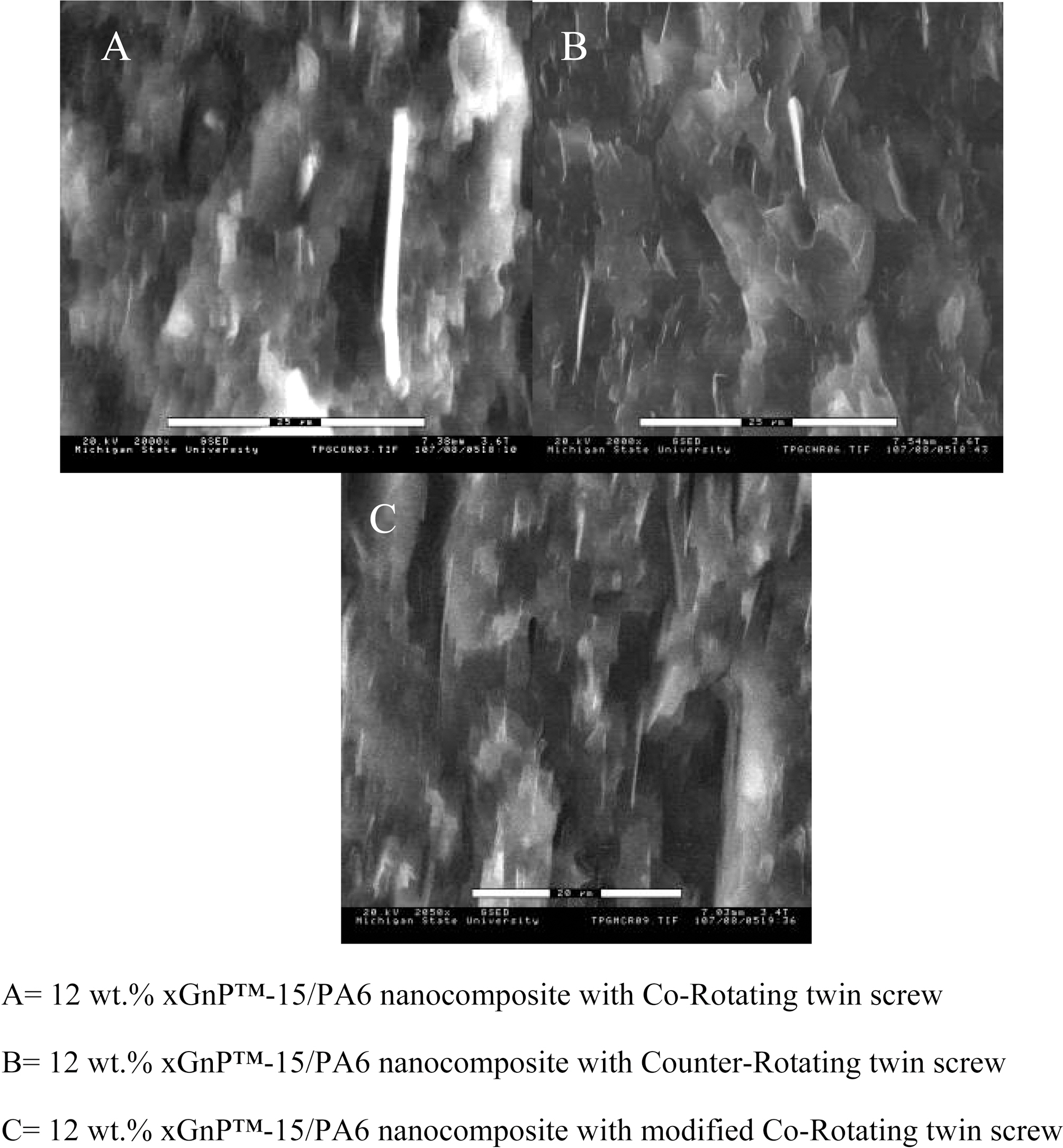
the matrix (Fig. 4b, c, and d). The xGnP displayed on the fracture surface are aligned due to the melt flow during injection molding. No evidence of xGnP aggregation was found. This indicates that the dispersion of xGnP-15 in the PA6 is relatively good. The 5 wt.% xGnP reinforced PA6 nanocomposite, processed by CoR showed a lower concentration of xGnP on the fracture surface, the CNR processed composite showed the highest xGnP concentration on the fracture surface, while the MCoR processed system showed the xGnP surface concentration between the previous two. More distinct xGnP-15 dispersion features at 12 wt.% xGnP PA6 nanocomposite are shown in Fig. 5. CNR processed nanocomposite showed the highest xGnP concentration on the fracture surface. These results suggest that the dispersion of xGnP in CNR processed PA6 nanocomposite is better than that in CoR and MCoR processed nanocomposites. This is consistent with the results Gorga [17] reported.
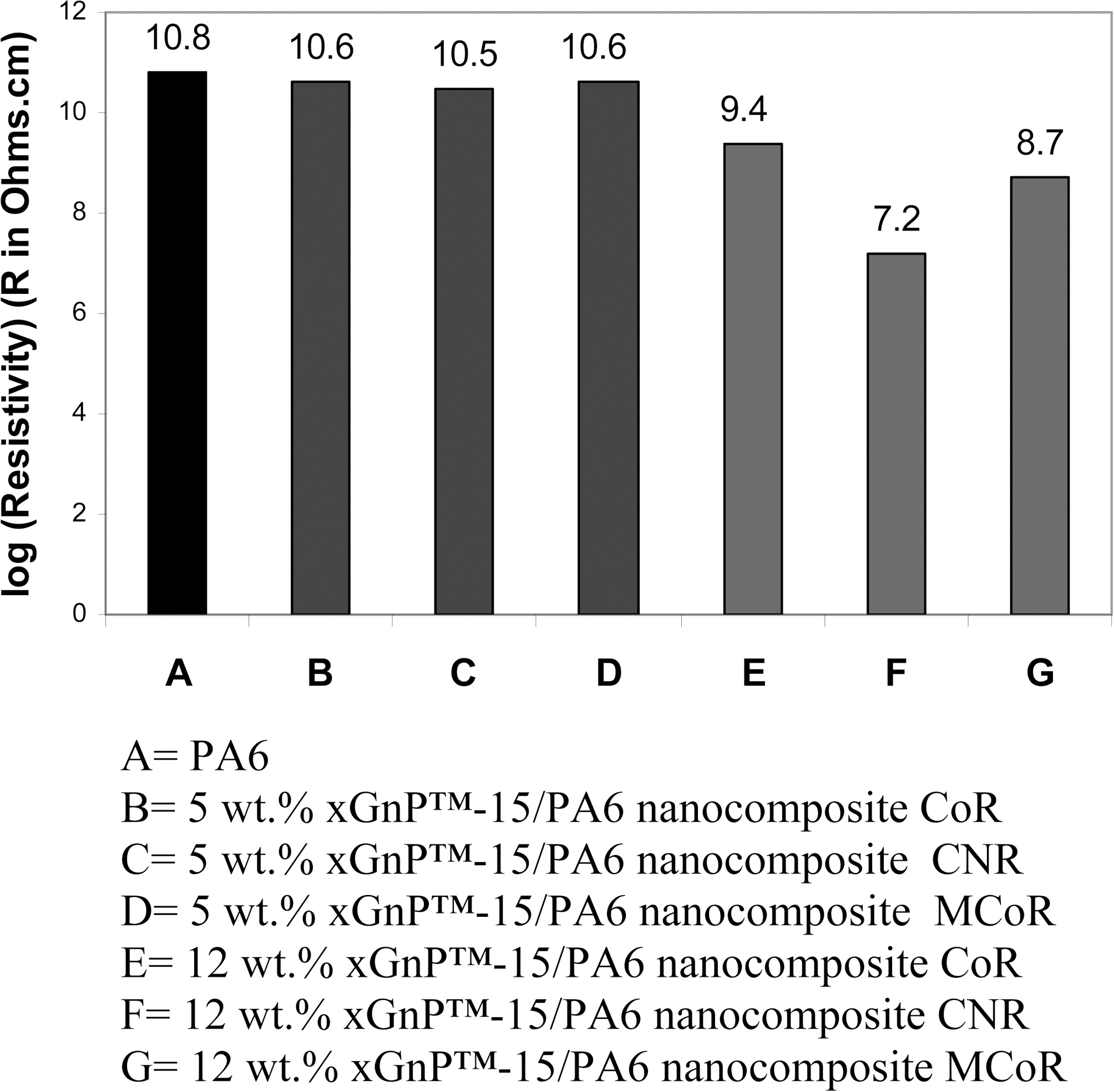
The resistivity of xGnP-15 reinforced PA6 nanocomposites is shown in Fig. 6. It was found that the resistivity of the xGnP-15 PA6 nanocomposite did not change when the xGnP-15 content was 5 wt.%. Normally, conductive filler reinforced polymer composites exhibits percolation phenomena. At the concentration below the percolation threshold, the conductive fillers is just dispersed to the
matrix and isolated by the matrix, so the composite is not conductive. At the concentration just above the percolation threshold the conductive fillers contact each other and form a conductive ‘percolated’ network, so the composite can be conductive. It has been found that the percolation point is around 6 vol.% for xGnP-15 PA6 nanocomposite processed through melt compounding [18]. 5 wt.% is below the percolation point.
When 12 wt.% xGnP-15 was used to reinforce PA6, a difference in the resistivity resulting from the dispersion was found. This is due to the fact that 12 wt.% is above the percolation region for xGnP-15 in PA6. The resistivity of CoR processed 12 wt.% xGnP-15 PA6 nanocomposite is the highest; that of the CNR processed nanocomposite is lowest and that of the MCoR processed is between them. The resistivity of the CNR processed nanocomposite is more than 100 times less than that of the CoR processed one. This tremendous difference in the electrical conductivity is caused by the better dispersion of xGnP-15 in the nanocomposite. Generally, the best dispersion caused the xGnP plate to be isolated from each other in the PA6 matrix. On the other hand, as the concentration is increased, the better dispersion allows the individual particles to contact each other to form conductive network at a given content of xGnP in the PA6 nanocomposite. The resistivity difference is directly related to the dispersion of xGnP-15 in the nanocomposite. The lower resistivity is due to the very good dispersion to form a conductive network along the melt flow direction, which is consistent with the result of the ESEM. Also, the CNR twin screw processed xGnP-15 PA6 nanocomposite possesses good electrical conductivity.
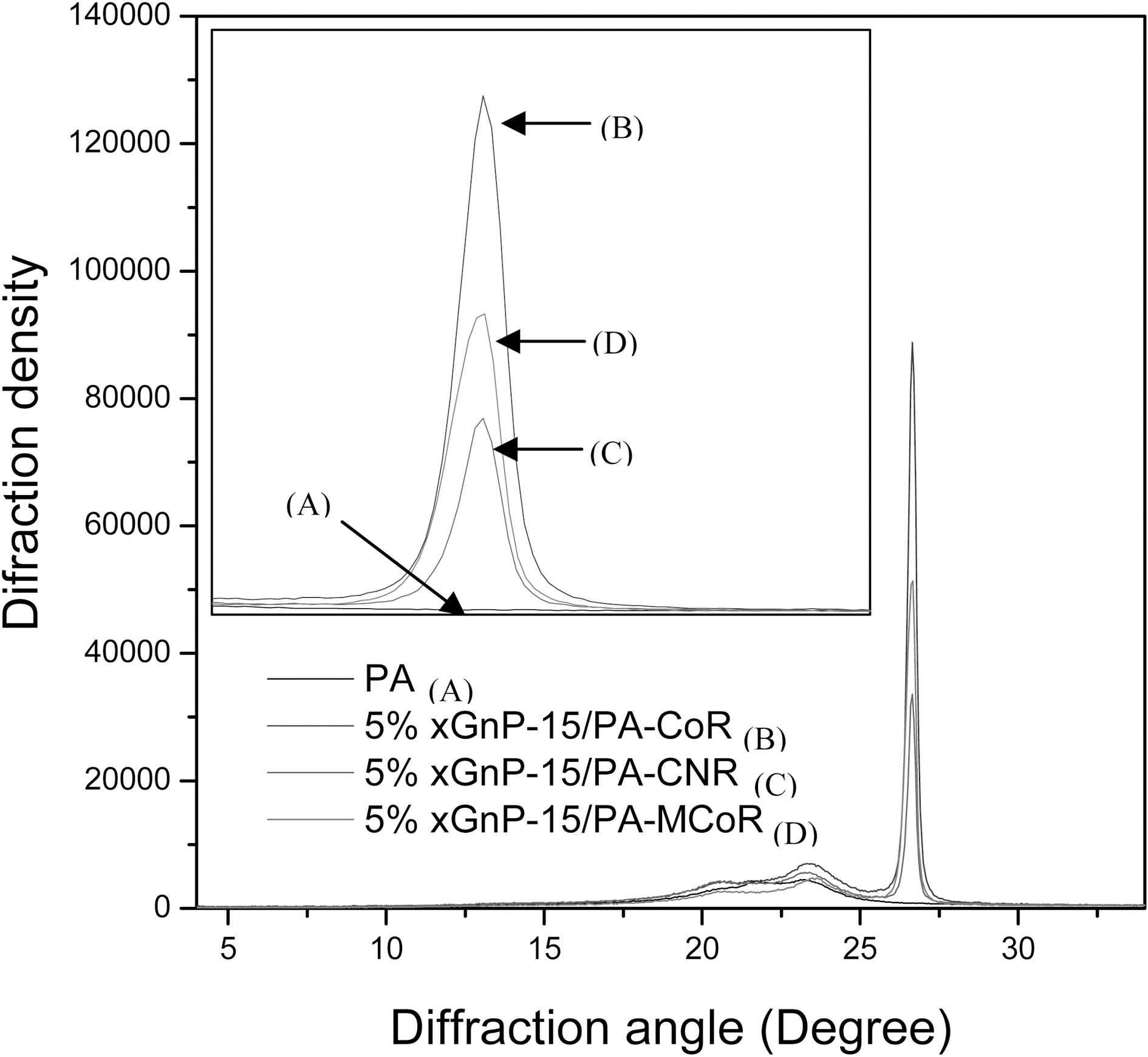
X-ray diffraction pattern of 5 wt.% xGnP-15 reinforced PA6 nanocomposites is shown in Fig. 7. xGnP-15 has a sharp peak around 26.5° with higher intensity that is assigned graphite d002 diffraction peak. Graphite is very difficult to get to a fully exfoliated state since graphite has extremely higher physical interaction between layers. In this case, the 5~10 nm thickness of xGnP still keeps the characteristic in the crystal structure of graphite. The normalized height of the graphite d002 peak can give useful information to determine the dispersion of xGnP-15 in PA6 nanocomposite through keeping the peak height of crystalline same. As shown in Fig. 7, in 5 wt.% xGnP-15 PA6 nanocomposite, the normalized intensity of xGnP changed with using different twin screw processed xGnP in the composite. The CNR processed nanocomposite showed lowest normalized graphite d002 intensity, but CoR processed nanocomposite showed highest normalized graphite d002 intensity.
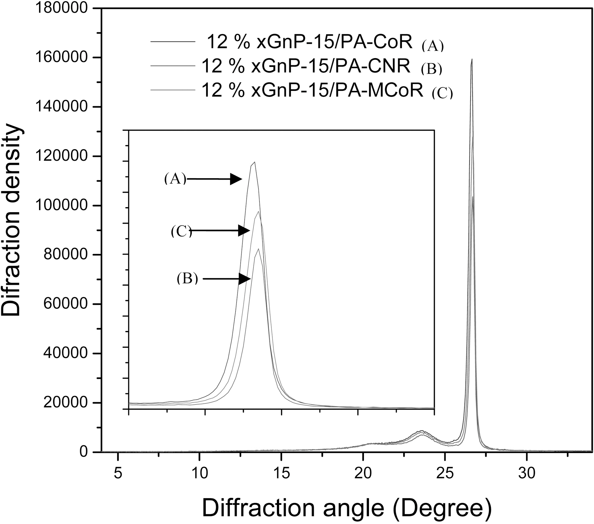
These 12 wt.% xGnP-15 PA6 nanocomposite showed similar trends as the 5 wt.% xGnP-15 PA6 nanocomposite, as shown in Fig. 8. The same amount of xGnP-15 in the PA6 nanocomposite, the normalized diffraction intensity of xGnP-15 plate at d002 crystal plane in CNR processed nanocomposite is lowest, that of the CoR processed one is highest; that of the MCoR processed one in the middle of the above two. It is known that the xGnP has been dispersed into PA6 matrix during processing. The better dispersion the more the xGnP plates are separated by the matrix. The more isolated xGnP plates, the weaker the diffraction peak. For a given number (a given weight percentage) of xGnP-15, the
more homogenous dispersion, the better chance to form a conductive network between xGnP plate along the current flow direction. Based on this argument, it is not difficult to understand why the CNR twin screw processed nanocomposite had the lowest diffraction intensity at xGnp d002 crystal plane and highest conductivity. If combined with the ESEM results, as well as resistivity with this normalized d002 graphite intensity in the nanocomposite, it can be easily concluded that the CNR processed PA6 nanocomposite showed the best dispersion of xGnP. This also indicates that the diffraction intensity of xGnP at d002 crystal plane in the nanocomposite can be used as a measure of the dispersion of xGnP in the nanocomposite.
Exfoliate graphite nanoplatelets (xGnP) reinforced polyamide 6 nanocomposites have been fabricated with extruder and injection molder and characterized for their mechanical properties, morphology, and resistivity. The influence of melt compounding processing on the physical properties of a polyamide 6 (PA6) nanocomposite reinforced with exfoliated graphite nanoplatelet (xGnP) has been studied. It has been found that counter rotation (CNR) twins crew processed xGnP/PA6 nanocomposite produces similar mechanical properties compared to co-rotation (CoR) twin screw processed or with CoR conducted with a screw design modified for nanoparticles (MCoR). The CNR processed nanocomposite has better xGnP dispersion than the (CoR) twin screw processed or the modified screw (MCoR) processed nanocomposites based on the ESEM morphology. The CNR processed nanocomposite at a given xGnP content has the lowest diffraction intensity of xGnP at d002 crystal plane. X-ray diffraction is a useful tool to measure the dispersion of xGnP in nanocomposites. The best dispersion of CNR processing also results in the highest electrical conductivity of the 12 wt.% xGnP-PA6 nanocomposite. These results indicate that better dispersion of an xGnP-PA6 nanocomposite is attainable in counter rotation twin screw processing than conventional co-rotation processing.