The outer cases or skins of almost all mobile phones and small digital equipment are made from various polymers due to their low density, flexibility, controllable transparency, ease of manufacture, and resistance to environmental corrosion [1]. The inherent problems found in polymer substrates are, however, a low surface energy and a poor adhesion to the films and coatings deposited on them. In order to help resolve these problems, various attempts have been made to modify the polymer surface in order to obtain an improved adhesion, wettability and printability [1-3]. The wide-spread use of wet chemical treatments for the polymer surface inevitably brings toxicity and environmental pollution, and so calls for alternative method, i.e. a surface treatment by dry plasma generated by a corona or arc discharge,
combustion, or ion-beams [4,5]. Depending on the treatment method and on the nature of the polymers, these methods also result in activation (radical formation), degradation (chain scission), cross-linking, and in the case of inert gases, radicals that can graft to a reactive group that promotes a recombination between the chains [6]. Among these treatment methods, the ionirradiation by ion beam sputtering (IBS) technique has been applied for carbonization and a change of solubility because it has a much higher energy level compared to the binding energy of the chemical bonds in a polymer molecule [7]. In addition, unlike other plasma deposition techniques, IBS makes it possible to minimize the thermal damage caused by plasma because it separates the cations from the electrons and so the substrate is not directly exposed to the ion beams. When the modified polymer surface exposed to the surface treatment is deposited with transparent oxide films, such as SiO2 and TiO2, it displays various colors which are caused by optical interference phenomena[8,9]. This “coloring” is important in many architectural and decorative applications, and attempts are also being made to apply this to the mobile phone and automotive industries [9].
In this paper, we report upon the effect of an in-situ ion-beam treatment on polycarbonate substrates by subsequently depositing TiO2 films onto the treated substrates.
An ion-beam assisted sputtering (IBAS) setup, which was equipped with two cold-cathode ion sources, one for the sur-
[Table 1.] The Experimental conditions for the surface treatment and the TiO2 film deposition.
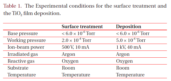
The Experimental conditions for the surface treatment and the TiO2 film deposition.
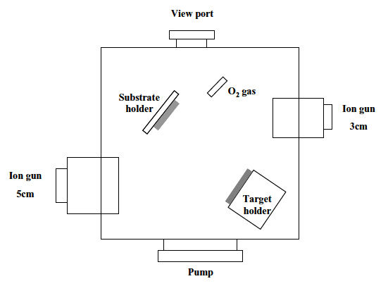
face treatment and the other for the sputtering, was used for the experiment. The substrates were 25 mm x 25 mm (3-mm-thick) pieces of commercial polycarbonate. In order to remove the contaminants, they were washed with isopropyl alcohol and de-ionized water in an ultrasonic bath and dried by blowing nitrogen gas on them. Both the surface treatment and the deposition of the TiO2 films were carried out by one of two cold-cathode type ion sources (3 cm-diameter and 5 cm-diameter, respectively), as shown in Fig. 1. The surface treatment was performed with either Ar+ ions or Ar+ ions mixed with oxygen. After a deposition of a thin Ti film (30 nm) on the treated surfaces, TiO2 films were deposited by reactive sputtering in a controlled oxygen atmosphere using a commercially pure titanium target. Table 1 shows the experimental conditions for the surface treatment and the deposition of TiO2 films.
The modification by surface treatment was identified using contact angle measurement (Phoenix 300, Surface Electro-Optics). The surface energy was then calculated using the Owens-Wendt [10] geometric mean equation. The surface morphology of the polycarbonate substrates was observed using an atomic force microscope (Nanoscope IIIa, DI Instrument). The colors observed from the TiO2 films on the polycarbonate were defined using the coordinates a* and b* belonging to the colorimetric space CIE a* b* system by a spectrophotometer (Konica, Minolta); the reflectance was measured using a UV spectrometer (Carry 500, Varian). The observed color of TiO2 films was then calculated by an interference equation defined by the thickness and the wavelength.
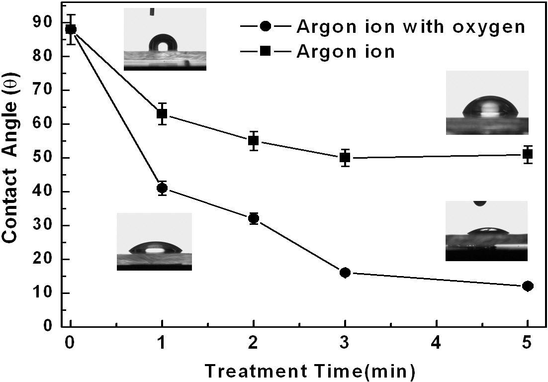
Figure 2 shows the changes in the contact angle of water droplets on top of the polycarbonate substrates after the Ar+ ion beam treatment with and without oxygen gas. When the substrate was treated by only Ar+ beams, the contact angles were reduced gradually from about 88° to 52°. A longer treatment did not yield any further improvement. However, when they were treated by Ar+ ion beams mixed with oxygen gas, the contact angles were further reduced, reaching a very low value of about 13°. The surface energy can be calculated using the Owens-Wendt [10,11] geometric mean equation incorporating the contact angle data, the dispersion, and the polar force of the liquid medium.
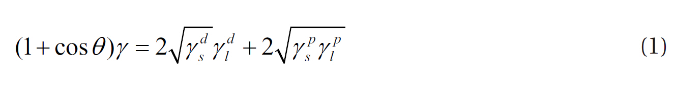
where γ, d, and p express the surface energy, the dispersion and the polar forces, respectively. In addition, s, l, and v represent solid, liquid, and vapor, respectively. The dispersion and
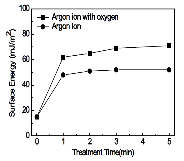
polar forces of the test liquids are 21.8 mJ/m2 and 51.0 mJ/m2 for water, and 37.0 mJ/m2 and 26.4 mJ/m2 for glycerol, respectively [12]. Figure 3 shows the results of the calculated surface energy derived by Eqs. (1) and (2). The surface energy values increased with the ion-beam treatment time; the use of oxygen gas with the Ar+ ion beams resulted in much higher surface energies when compared to the substrates treated by Ar+ ion beams only. The reduction of the contact angles and the increase of surface energy are, without a doubt, due to the modification of the surface of the polycarbonate substrates by the ion beam irradiation. Hall et al. [13] has reported that the cross-linking, chain breaking and chemical reaction on the polymer surface may caused by the bombardment of the activated gas species. Since Ar is an inert element, the Ar+ ion-beam bombardment on the polycarbonate surface must have caused chain breaking, such as C-C, C-H and C-O, and cross-linking. The radicals originating from the chain breaking reaction readily recombine because they are not thermodynamically stable [14]. In addition, chemical reactions may have occurred by the introduction of the reactive oxygen gas at the activated polycarbonate surface by the Ar+ ion beam irradiation. When treated only by the Ar+ ion-beams, the reduction of the contact angle might be attributable either to an increase of the roughness from the etching effect of the Ar+ ion-beams or the increase of the surface energy by the chain breaking mechanism. On the other hand, when treated by the Ar+ ion-beams mixed with oxygen gas, the unstable radicals generated by the chain breaking can combine with the oxygen and recombine with other radicals. It is known that the chemical reaction between the polymer radicals and the oxygen should create hydrophilic
groups, such as -OH, which can be related to the reduction of the contact angle and the change of the surface energy [7,14].
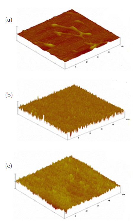
Figure 4 shows the typical surface morphology images obtained from an AFM. The treated surfaces show a nano-scaled roughness of about 8.61 nm and 8.29 nm for the Ar+ ion-beams without and with oxygen, respectively, due to the damage created by the ion bombardment. Although the surface roughness remains about the same, the addition of oxygen during the Ar+ ion bombardment reveals a strong impact on the surface energy and the contact angle, which may only be explained by the occurrence of the chemical reactions mention above.
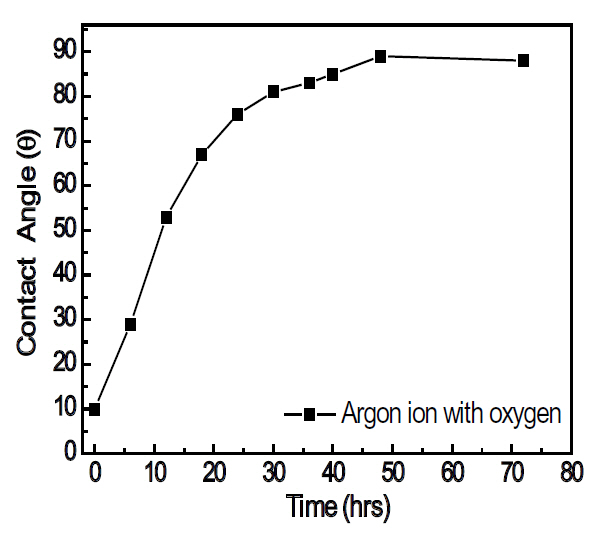
When the treated polycarbonate substrates are exposed for
[Table 2.] The surface roughness values before and after the surface treatments.
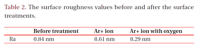
The surface roughness values before and after the surface treatments.
prolonged time in air, the contact angle recovered almost completely to 88°, as shown in Fig. 5, even though the surface roughness does not change. Therefore, it is confirmed that the surface energy was enhanced by the surface and chemical reactions, with the modified surface having a relatively short life time.
After depositing a Ti buffer layer of about a 30 nm thickness on the treated surface, TiO2 films were deposited on the treated surface by utilizing the titanium metal target and the reactive
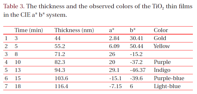
[Table 3.] The thickness and the observed colors of the TiO2 thin films in the CIE a* b* system.

The thickness and the observed colors of the TiO2 thin films in the CIE a* b* system.
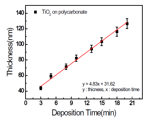
sputtering technique. Figure 6 shows the change of the TiO2 film thickness with the deposition time, demonstrating a linear relationship between the deposition time and the film thickness.
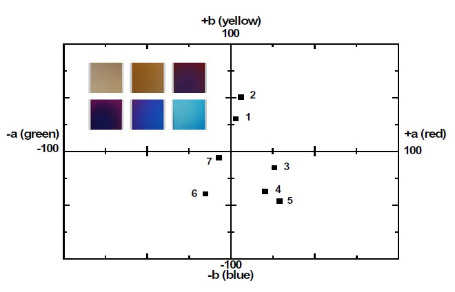
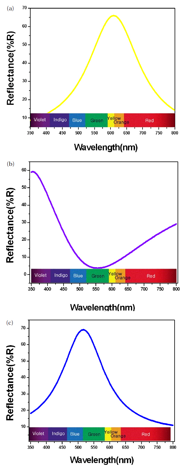
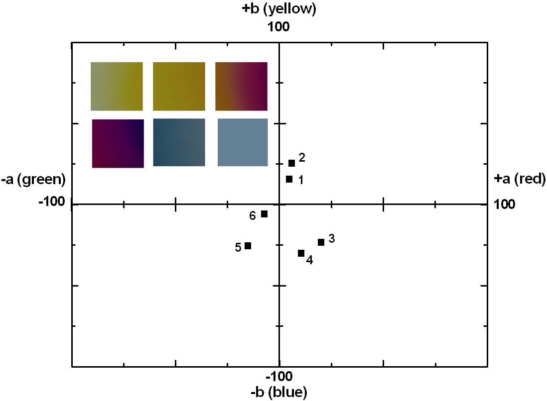
The coloring behavior of the TiO2 films deposited on the transparent polycarbonate substrates were characterized by the CIE a* b* scale system, measurable by a spectrophotometer. The a* value represents the axis red (positive) to green (negative), the b* value represents the yellow (positive) to blue (negative) axis [9,15]. The results of the CIE system analysis for the TiO2 films are shown in Fig. 7. Each of the points represents the color parameters of the TiO2 films interpreted in the a*-b* diagram. The first color on the surface was yellowish for a deposition time of 8 to 10 minutes; the next colors were violet and blue for the deposition times of 15, 18 and 20 minutes, respectively. A depiction of the actual colors of the TiO2 films is shown in the inset of Fig. 7. The color appearance of obtained the TiO2 films shows the different reflectance spectra over the visible wavelength range (about 400 to 700 nm), as shown in Fig. 8. Various colors have corresponding specific wavelengths, and, as a result, different reflectance spectra are obtained. For example, the yellow TiO2 film indicates a reflectance at about 600 nm. The other films indicate strong reflectance at about 350 nm and 500 nm, for the violet and blue colors, respectively. This phenomenon, i.e. the change of colors dependant on the thickness, is well known and is due to the optical interference phenomena between two neighboring light waves, which may be constructive if they are in phase, or destructive if they are out of phase. It is wavelength dependent and differs over the spectral region for a given thickness of oxide. The destructive interference takes place with an optical thickness of a quarter wavelength (λ/4) and the reflectance resulting from the destructive interference is described by:

where n and d are the refractive index and thickness of the oxide film, respectively. In contrast, the reflectance resulting from the constructive interference is described by:

The thickness values of the oxide layer and the wavelength can be calculated from these equations. The TiO2 films, deposited by ion-beam assisted sputtering, showed different thicknesses and accompanying color and wavelength, as shown in Figs. 6 and 7. The refractive index value of the TiO2 films, measured by an ellipsometer,was about 2.27. With the known wavelength (λ) and refractive index (n) values, the thickness of the TiO2 films can be calculated and estimated, as shown in Fig. 7. The first cycle showed yellow, violet, and blue; the second circle also periodically showed the changing color behavior indicating yellow, violet, and blue with the increasing thickness of the TiO2 films. Fig.9 shows the reappearance of the colors with an increasing TiO2 film thickness after a deposition time of 20 minutes. It shows that the colors changed in the yellow-violet-blue sequence, similar to the results shown in Fig. 7, confirming the presence of a periodical tendency.
The surface treatment and deposition of TiO2 films were attempted utilizing an ion-beam assisted sputtering system equipped with two cold-cathode type ion sources. After the Ar+ ion beam bombardment, the contact angles of water droplets were reduced from about 88° to 52°, and further decreased to about 12o when mixed with flowing oxygen gas. It was found that the polycarbonate surface gradually changed from hydrophobic to hydrophilic with an increased surface energy. It was also found that the roughening caused by the ion bombardment had little effect on the increase of surface energy. The TiO2 films on the ion-beam treated polycarbonate substrates showed varying colors with periodic order dependant on thickness due to the optical interference phenomena.