The increased demand for high maneuverability of modern missiles requires excellent autopilot performance over a large flight envelope. The main difficulty in missile autopilot design is the influence of high angle-of-attack aerodynamic phenomena on stability characteristics (Hemsch, 1992). As a missile executes a high angle-of-attack maneuver, the forebody vortices can become asymmetric and give rise to significant lateral-forces and yawing moments. Classically, missile autopilots are designed using gain scheduling approaches in roll, pitch, and yaw channels (Blakelock, 1991; Shamma and Athans, 1992; Shamma and Cloutier, 1993; White et al., 2007). However, the performance of singleaxis autopilot design approaches are limited within some flight boundaries because aerodynamic coupling effects and their parameter dependencies in large angle-of-attack aerodynamics could not be considered. In this context, the design of a three-axis missile autopilot has been studied using linear and nonlinear control approaches (Choi et al., 2008; Devaud et al., 2001; Kim et al., 2008). These methods are based on gain scheduling techniques by local linearization, and demonstrate some improvements from a practical point of view.
In this paper, a three-axis missile autopilot design with a multi-objective output-feedback control theory is presented. Because high angle-of-attack aerodynamics is highly nonlinear and estimates of the aerodynamic coefficients are very imprecise, a mix of
This paper is organized as follows. In Section 2, we give an overview of multi-objective output-feedback control theory. Section 3 describes our formulation of the missile control problem. Section 4 describes strategies and numerical simulation results for the designed autopilot. Our conclusions are provided in Section 5.
This section gives a brief overview of multi-objective output-feedback synthesis via the LMI approach described in (Chilali and Gahinet, 1996; Gahinet and Apkarian, 1994). For the missile autopilot design problem, the control objectives include
Consider a generalized plant with
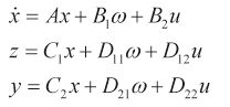
where A∈Rnxn, D12∈Rp1xm2, and D21∈Rp2xm2. In addition,
2.1 Multi-Objective LMI Formulation
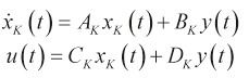
The LTI controller
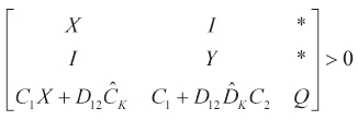
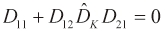
For the LMI approach to multi-objective synthesis, nonlinear terms added in the output feedback case should be eliminated by an appropriate change of controller variables. This change of controller variables is implicitly defined in terms of the Lyapunov matrix
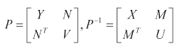
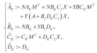
The new controller variables can be written as
The mixed
with the shorthand notation
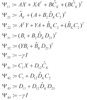
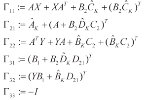
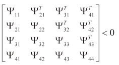
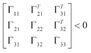
Note that the multi-objective output-feedback synthesis is an LMI problem of the form
After solving the synthesis LMIs, the controller computation proceeds as follows:
Find a nonsingular matrix M, N to satisfy MNT = I-XY via SVD.
Solve the linear equation (Eq. 4) for the controller K(s) by computing (Eq. 13).

This LMI optimization problem can be efficiently solved with the LMI Control Toolbox (Gahinet et al., 1995). The solution of the LMI problem gives us an upper estimate of the suboptimal
3. Missile Control Problem Formulation
3.1 Missile Model and Autopilot Requirements
We considered a three-axis nonlinear missile model of a skid-to-turn cruciform missile with a high angle-of-attack. Sensors and actuator modeling were also taken into account. We assumed that the missile plant had 5 degrees of freedom (DOFs) with the fixed altitude and longitudinal velocity. Also, rigid body dynamics was considered. Under these assumptions, the 5-DOF rigid body equations of motion were expressed using differential equations describing the translational motion and rotational motion as follows:
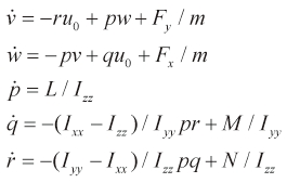
We considered a three-axis nonlinear missile model of a skid-to-turn cruciform missile with a high angle-of-attack. Sensors and actuator modeling were also taken into account. We assumed that the missile plant had 5 degrees of freedom (DOFs) with the fixed altitude and longitudinal velocity. Also, rigid body dynamics was considered. Under these assumptions, the 5-DOF rigid body equations of motion were expressed using differential equations describing the translational motion and rotational motion as follows:
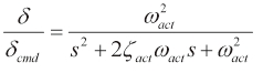
where δ, δcmd, Ω act, and ξ act are the actual fin deflection, commanded fin deflection, natural frequency, and damping coefficient, respectively. The state-space form of the missile model is written as
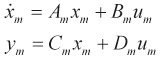
where
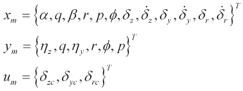
In this expression, α , β , and φ are the angle of attack, sideslip angle, and bank angle, respectively; δ z, δ y, and δ r are the actual tail deflections in the pitch, yaw, and roll axes, respectively; and η z and η y are pitch and yaw acceleration commands, respectively. The inputs to the missile plant are commanded tail deflections δ zc, δ yc, and δ rc. Therefore, the accelerations, bank angle, and angular rates are available for feedback. The total incidence angle α ' = acos(cosα cosβ) was used for scheduling, but the aerodynamic roll angle φ ' = atan(tanβ sinα ) was not measurable in this missile problem.
The aim of the proposed autopilot design is to steer the missile to track the acceleration guidance commands generated by an outer loop and stabilize the missile airframe at a given bank angle. The stabilization of the bank angle is a critical requirement for controlling a highly maneuverable missile. However, the aerodynamic roll angle is not measurable in a practical context. To deal with this problem, we found a dynamic controller
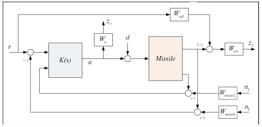
3.2 Interconnected System Model
The performance specifications for the closed-loop system in terms of multi-objective control are as follows:
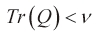
Guarantee an upper bound on the L2-induced gain γ of the operator mapping z to Ω.
Minimize an upper bound on the variance of z2 due to the disturbance Ω.
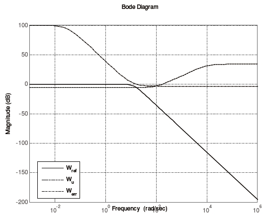
These performance requirements of the closed-loop system were transformed into the multi-objective control framework with weighting functions. Weight functions were selected to account for the relative magnitudes of signals, frequency dependence, and relative importance. This method allows the controller designer to apply classical loop-shaping concepts to obtain good performance while optimizing the response near the system bandwidth to achieve robust stabilization. The continuous time synthesis plant
The angle-of-attack α and the side-slip angle β were not available by measurement only. In this missile control problem, α' and φ' can capture the nonlinearities of the missile plant during a high angle-of-attack maneuver. However, φ' is not available for scheduling while α' can be estimated. Modern missiles suffer from variations in aerodynamic roll angle because of their extended flight regimes. Thus, an autopilot should be robust against aerodynamic roll angle variations. In this section, we present our simulation results for the three-axis missile autopilot design using LMI techniques.
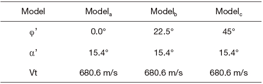
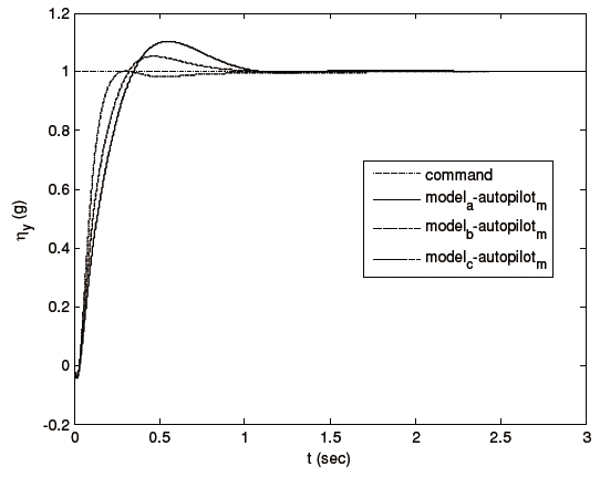
Linear time-invariant (LTI) models of a nonlinear missile plant were derived at three fixed operating points. Table 1 shows the trim conditions of each operating point. V t is the total velocity of the plant. The multi-model includes Modela, Modelb, and Modelc. Since LMI constraints can incorporate multiple models with the design criteria, we can formulate the proposed autopilot design strategy systematically.
[Table 1.] Trim conditions for local linearization

Trim conditions for local linearization
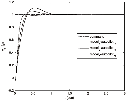
Figures 3-5 show the tracking performance of the proposed scheme. Notice that the autopilot guarantees
We proposed a three-axis missile autopilot design with multiobjective control synthesis. Our simulation results for the missile plant demonstrate the effectiveness and performance of the proposed control strategy in spite of its limitations. The results show that the designed autopilot provided satisfactory performance for nonlinearities over high angle-of-attack flight boundaries and uncertainties in the aerodynamic roll angle estimation.