A full engagement of a missile against an attacking missile consists of three phases: launch, mid-course and terminal homing phase. For long or medium range engagement the missile generally cannot lock on to the target so that the mid-course guidance law will be applied to the missile. Midcourse guidance phase refers to the procedure that guides the missile to a terminal handover point in order to acquire the target motion through its on-board sensor. The midcourse guidance law differs significantly from the guidance logic for the terminal homing phase due to the inherited characteristic of the mid-course guidance: it must not only find the best condition for the terminal homing phase, but also deliver the missile to that condition using only the target motion data updated by the external source such as a plane, ship, or ground base. Although there are a number of objectives for the mid-course guidance, it is possible to classify them into two main categories.
Firstly, the onus is on the mid-course guidance to achieve the best terminal handover condition, i.e. to provide certainty that the missile can reach the target. For a target at a great distance, the mid-course guidance opts to maximize the terminal velocity and/or minimize the energy loss in order to gain high velocity and manoeuvrability advantages for the terminal homing guidance. Minimizing the flight time is commonly relevant to a close in target problem, since the missile should intercept the target before attacking its objective (Song and Tahk, 1998). The necessary conditions for an optimal mid-course guidance problem form a twopoint boundary-value problem (Kirk, 1970). However, it is unfeasible not only to derive the analytical solution but also to find a numerical solution in real time by any present-day on-board computer.
Several approaches have been proposed to solve the optimal mid-course guidance problem. Song and Tahk (1998, 1999, 2001) have addressed artificial neural networks for the mid-course guidance algorithms to generate suboptimal guidance commands in a feedback fashion. Whilst this approach can overcome the difficulty in deriving an on-board optimal guidance law, it is difficult to cover all the region of the input vector for neural network training, and the stability cannot be guaranteed. To find a real time sub-optimal guidance algorithm, singular perturbation technology (SPT) (Cheng and Gupta, 1986; Dougherty and Speyer, 1997; Menon and Briggs, 1990) and linear quadratic regulator (LQR) (Imado and Kuroda, 2009; Imado et al., 1990) have been proposed. However, a guidance law based on SPT does not result in a true feedback control, and the LQR type guidance algorithm needs a large set of database.
Another important objective in the mid-course guidance is protecting and defending an area. For instance, two primary tasks of the maritime air defence area are protection of sea traffic or convoys and coast line protection against attacking weapon systems such as anti-ship missile (ASM), which has a high kill probability and low detectability. It is important that the mid-course guidance algorithm guides the missile to the acquiring point in order to guarantee reachability of the guidance in the terminal homing phase. However, the missile cannot guarantee to intercept and destroy the challenging missile before it has struck its target within the defending area.
Over the past decades, a range of missile genres have been developed and each of them has well published advantages and disadvantages. Yet there has been little research dealing with naval area defence and protection directly. For warships to continue their primary role, it is essential that air defence for a single unit, be it large or small, a close escort or a major surface group, provides a comprehensive defence against all types of air threat, from the sea skimmer to the high diving missile in addition to attack aircraft and weapon carrying unmanned aerial vehicles.
In our study represented in reference (Robb et al., 2005a, b), the earliest intercept line (EIL) concept is proposed for a midcourse guidance using shortest path technologies 'Dubins' (Dubins, 1957). The guidance law can improve reachability under consideration of lateral acceleration saturation and unpredictable target missile manoeuvre. Moreover, since the guidance algorithm is based on differential geometry, it is easy to show whether or not the missile can intercept the challenging missile while protecting the defending area. However, it is impossible to derive an analytical solution using the proposed algorithm and difficult to analyse the performance of the guidance algorithm mathematically
This paper will describe an analytical solution and performance validation for a generalized mid-course guidance problem in area air-defence which improves reachability and overcomes the weakness of the previous study (Robb et al., 2005a, b). As will be seen, the proposed mid-course guidance strategy is derived based on the earliest
2. Earliest intercept geometry
The guidance algorithm described in this paper is a subset of possible solutions for a non-manoeuvring target, which have been proposed in our previous research (White et al., 2007) using different geometry concepts (Lipschutz, 1969; O'Neill, 1997). The algorithm is identical to the concept of proportional navigation guidance (PNG). Therefore, this gives solutions as robust as PNG algorithms, and allows for greater flexibility in the choice of trajectory which enhances reachability. Moreover, it allows predicting the precious
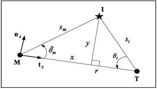
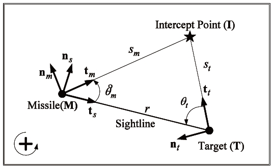
Figure 1 shows the case in which a target is flying in a straight line at constant velocity

In order for the missile to arrive at the

The ratio of the trajectory lengths is then given by:
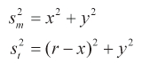
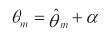
As proposed in our previous study (White et al., 2007), implementing the cosine rule to the
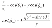
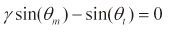
where θm and θt are the missile-to-sightline angle and the target-to-sightline angle, respectively; and,
If a challenging missile heading angle and the range of
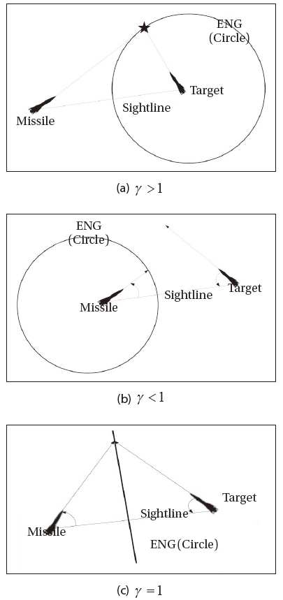
From these figures it can be seen that a velocity ratio larger than unity produces possible missile positions for intercept both behind and in front of the target. The
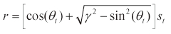
The
The geometry is drawn using the sightline axes centred in the missile, hence x is along the sightline and y is normal to it, with
Using Eq. (3), this yields:
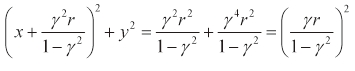
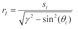
This equation represents a circle with radius
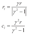
The speed ratio γ is key parameter of Eqs. (2-5). As shown in Eq. (6), the centre of the intercept circle
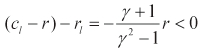
the target will be always located in the circle as shown in Fig. 2(a). However, if we have γ smaller than 1, there is the range of θ t for which:
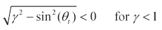
which implies that for some geometry, a real solution is not possible and the missile will not be able to intercept the target. Such a condition is shown in Fig. 2(b). For γ smaller than unity, the centre of the intercept circle is negative, i.e. the centre is placed along the sightline but on the opposite direction to the target. Furthermore, the radius of the circle is greater than the distance between the centre and the missile so that the missile will be always inside the circle. Therefore, if the ratio is greater than unity the defended area of the missile is outside the circle; however, the defended area is inside the circle for γ smaller than unity. This property can be used to allocate the missile in the position guaranteeing the area defence: for γ larger than unity, the missile has to launch when every defended object is located outside the circle, and the missile makes sure the defended objects are placed inside the circle where γ is smaller than 1
For γ smaller than unity, there are two matching conditions for the ratio
For the case in which the missile and target are travelling at the same speed, we have γ equal to unity and the
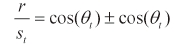
There is no longer an imaginary solution, and there are now two real solutions given by:
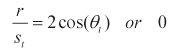
The first solution implies a geometry which produces an isosceles triangle solution as before, for

Note that this means for γ equal to unity, the
The locus also has another interpretation. Given that the target is travelling at constant velocity in a fixed direction, as shown in Fig. 2, the locus represents the earliest intercept that the missile can achieve. This is based on the fact that the shortest distance between two points is a straight line. Hence the straight line
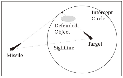
The EIG concept implies that if the target manoeuvres away from a straight line trajectory for striking its aiming object, then the missile travelling on a straight line trajectory can achieve the intercept outside the defended zone defined by the EIG. As mentioned in the previous section, the defended zone is outside the EIG for γ greater than or equal to unity and inside the EIG for γ smaller than unity. Conversely, if the missile deviates from a straight line trajectory, then the
Due to physical and operational conditions of the missiles, the missile cannot always protect the defended objects or area. Figure 4 represents one of these cases when the missile velocity is greater than that of the challenging.
If it is possible to control the EIG to allocate the defended area within updated defended zone, the problem can be resolved. Therefore, it is needed to control the EIG in order to improve reachability and performance of the guidance algorithm. This can be achieved to some extent by examination of the impact triangle shown in Fig. 1.
The
where rI and rt are the position vectors of the

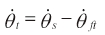
where θ ft is the heading angle of the challenging missile. The intercept condition must obey the equation
Differentiating the above equation with respect to time gives:
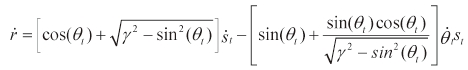
Then,
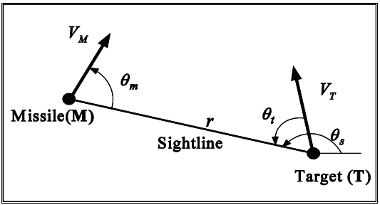
In Fig. 1, the sightline-to-missile angle is the desired angle to intercept a non-manoeuvring target. However, it can be different from the desired angle for a deliberate purpose, or due to the missile's physical constraints as shown in Fig. 5. To derive the range rate and the line-of-sight (LOS) angle rate, consider a guidance geometry of a challenging missile and a defending missile whose heading angle is either the same as or different from the desired angle.
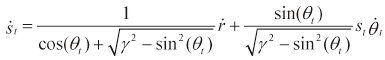
From the guidance geometry, the first time derivatives of the range and LOS are given by:
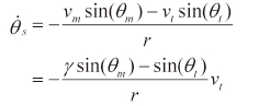
where θm is the real sightline-to-missile angle. Substituting Eq. (17) into Eq. (16) yields:
Moreover, substituting this equation into Eq. (13) gives:
Moreover, substituting this equation into Eq. (13) gives:
For analysis of the guidance geometry, consider the direct intercept guidance for either a manoeuvring or nonmanoeuvring challenging missile under the assumption that the missile can change its heading angle instantaneously; the missile is always heading for the

For a direct intercept guidance:
For a direct intercept guidance:
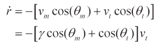
From the intercept matching condition, we have:
Then, the
Note that since:
and the tangent vector, t, at the
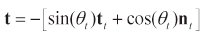
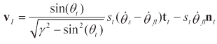
the

and the
Now, consider a non-manoeuvring target, but the missileto- sightline angle θm is different from the desired angle θm for the intercept on the purpose controlling the

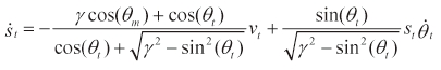
Furthermore, the target-to-sightline angle rate is the same as that of the sightline:

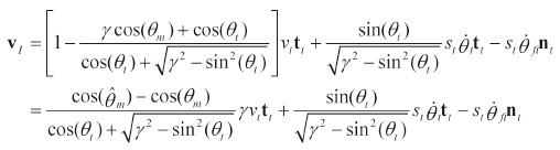
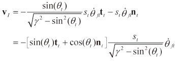
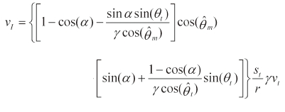
Substituting these two equations and Eq. (18) into Eq. (20) yields:
Note that the equation shows that it is possible to control the
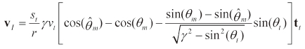
Then, the
Since the
the
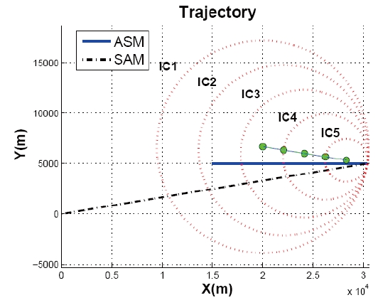
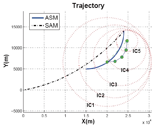
Surface to air missile versus Anti ship missile (SvA) problems are considered to verify the proposed missile midcourse algorithm in area air-defence. Two SvA scenarios are classified by different anti ship missile (ASM) lateral acceleration: the acceleration is zero in the first scenario, and 10
Note that it is possible to notice that the speed ratio γ is 2 from Table 1. In the simulations, it is assumed that two missiles are lag free systems and can change their flight heading angle instantaneously. Simulation results are represented in Figs. 6 and 7.

Initial conditions
ICs in the figures represent the intercept circle. As shown in Fig. 6, the
In this paper, the missile mid-course guidance law in area air-defence is proposed using the EIG concepts and differential geometry to resolve single-to-single problem. Its characteristics are mathematically analysed under several assumptions to improve reachability and overcome the drawbacks in our previous studies (Robb et al., 2005a, b). Furthermore, its performance is examined by using some numerical examples. The proposed method can be used in the launch phase because it provides the defended zone defined by the EIG. A launch window and launch point can be determined by finding a moment and position that the guidance algorithm assures all the defended area and objects are inside the defended zone.
For the next step of in the series of the mid-course guidance law in area air-defence, physical and operational constraints of the missiles will be considered to analyse the effect on the EIG. Furthermore, the multiple defending missiles versus multiple challenging missiles problem will be considered in order to develop cooperative missile guidance techniques and improve global defence performance.