Nowadays, as the application range of portable displays has increased widely, transflective LCDs, which have a high image quality in any light environment, need to be developed. Recently, several transflective LCDs have been proposed. One of the imperative key requirements for transflective LCDs is that the device must show a wide-viewing-angle in the T- region. Among these LCDs, in-plane switching (IPS) [1-4] and fringe field switching (FFS) [5-17] devices associated with the horizontal switching of the LC director with a wide viewing angle are achieved and charaterised. The FFS mode shows a much higher light efficiency than the IPS or vertical alignment modes [18]. Interestingly, the FFS mode is known to have a different twist angle distribution at the different electrode positions due to the mutual effect of the vertical and horizontal fields generated between the common and pixel electrodes. In the FFS mode, the electro-optic characteristics of the device strongly depend on the sign of the dielectric anisotropy of the liquid crystal [19]; there is a higher light efficiency with a negative dielectric anisotropy as compared to a positive dielectric anisotropy.
In the transflective FFS-LCD, different twist angles 22.5° and 45° in the R- and T- regions respectively were used, however the display shows unmatched gamma curves in both the R- and Tregions. In this paper, we explore the effect of a transflective display driven by the fringe field with negative dielectric anisotropic liquid crystals. In order to match the optical state for both the Rand T- regions, we used a patterned in-cell retarder (ICR) in the R- region of the proposed cell structure. The center of the pixel electrode with a low rotation angle is used for the R- region however a high rotation angle is used for the T- region. By optimizing the electrode conditions of proposed cell structure and single gamma characteristics, a new FFS transflective LCD with a single cell gap can be realized. In this research paper we show the optimized cell with a single gap and a single driving circuit with a wide viewing angle in both the R- and the T- regions.
2. THE SWITCHING PRINCIPLE OF THE TRANSFLECTIVE DISPLAY ASSOCIATED WITH AN IN-PLANE ROTATION
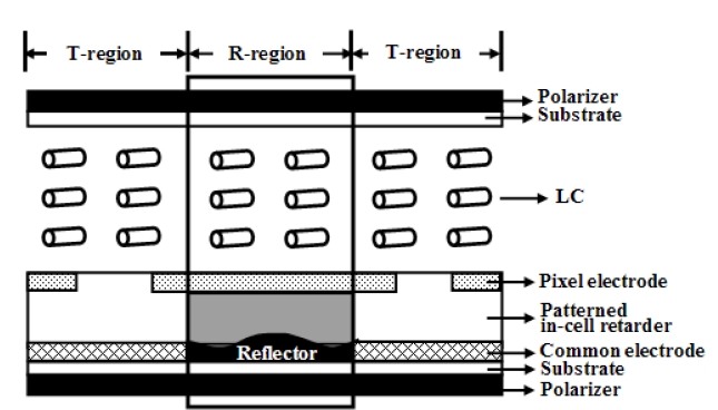
Figure 1 shows the cell structure of the proposed novel transflective display driven by the fringe field switching. In this display device, the ICR width is less than that of a pixel electrode and exists above the common electrode in the R-region with a retardation value λ/4 while it is in an isotropic state in the Tregion. It consists of two crossed polarizers, in which one of the polarizer axes coincides with the rubbing axis of the liquid crystal. As we know, when a uniaxial LC medium exists under crossed polarizers, the transmittance (T) and reflectance (R) is given by:
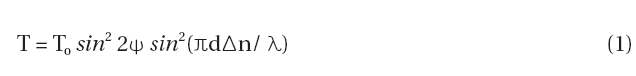
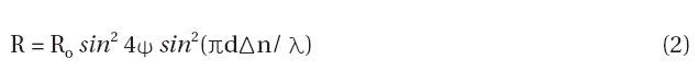
where ψ is the angle between the input polarizer and the director of liquid crystal,
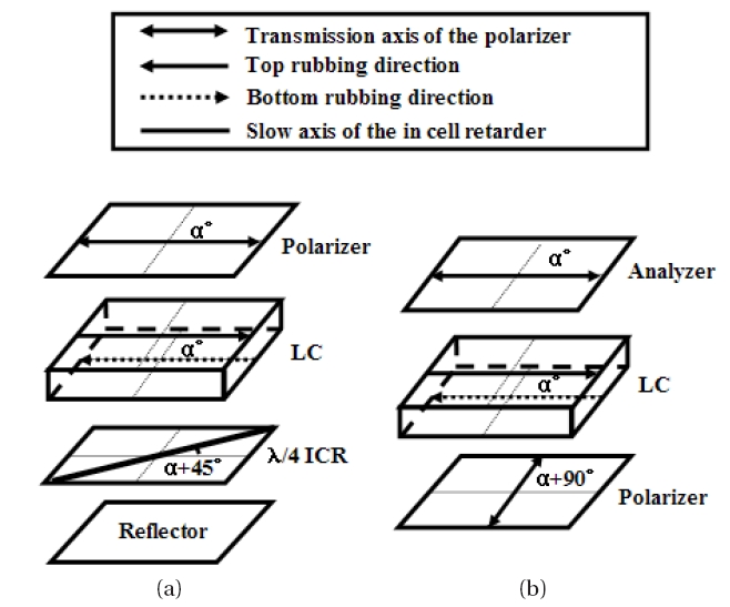
Figure 2 shows the optical configuration of the proposed transflective display. For the R-region, the rubbing angle of the liquid crystal is set to about 45° from the optic axis of the in-cell retarder (ICR) with a quarter-wave (λ/4) plate; the top polarizer and rubbing direction of LC coincide with each other. Maximal reflectance and transmittance can be achieved in the presence of an electric field, if the R- and T- regions are designed for an average twist angle of nearly ψ = 22.5° and 45° respectively, with a d~n = λ/2 for both regions. So that the linearly polarized light can rotate by 45° and 90°, in the R- and T- region, respectively.
In the R- region, in the absence of an electric field, the linearly polarized light coming out from the polarizer propagates along the slow axis of the liquid crystal director without changing its polarization state. After passing through the ICR, the light becomes circularly polarized. This circularly polarized light is reflected back from the reflector and propagates through the retarder again and becomes linearly polarized with a phase change of 90° from the original incident light. As a result, the light can not pass through the analyzer and thus the R-region appears to be black. In the bright state, the LC rotates 22.5° due to the fringe-field and the linearly polarized light changes in a 45° direction after passing through the LC and proceeds to the ICR located at the optics axis of 45° with respect to the analyzer. Hence, the light goes without changing its polarization state.
After reflection, the light again propagates through the ICR and then passes through the liquid crystal with a change in its phase angle of 45° in the reverse direction, resulting in a bright state. In the dark state of the T- region, the linearly polarized light from the polarizer passes through LC layer without changing its polarization state, like in the conventional FFS mode. Thus it is blocked by the analyzer, showing a dark state. In the bright state, the liquid crystal director rotates 45° so that the input light is rotated 90° and hence appears bright through the analyzer. Thus, the device is created for normally black and bright modes in both the R- and T- regions.
In order to determine the optimal condition of a proposed transflective display driven by the fringe field, a computer simulation was performed using the commercially available software "LCD master" (Shintech, Japan). The motion of the LC director was calculated by using the Eriksen-Leslie theory and an optical calculation was based on the 2×2 extended Jones matrix [20]. For the simulation, positive and negative dielectric anisotropies (δε) of an equal magnitude of 20 were taken with a cell retardation (dδn) value of 0.36 μm. The surface tilt angle of the LC was 2° with respect to its horizontal field. The initial rubbing directions of the positive and negative dielectric anisotropy of the liquid crystal were 10° and 80°, respectively. The transmittances of the single and parallel polarizers were assumed to be 41%, and 35%, respectively. For this setup, the pixel electrode width was varied from 6 μm to 12 μm while the distance between the two electrode slit was kept constant at 3 μm. The dielectric anisotropy of the ICR was 5 with a thickness of 1 μm.
4. THE SIMULATION RESULTS AND DISCUSSION
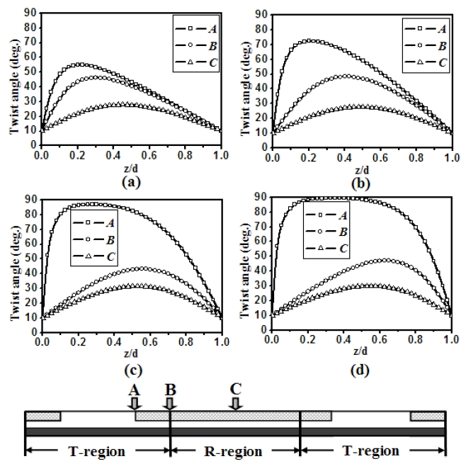
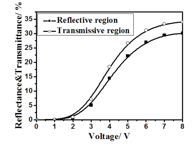
Figure 3 shows the twist angle distribution of the LC director using negative dielectric anisotropy at three different positions of the pixel electrode. As shown in the figure, the rotation degree of the LC director at center position (position C) of the pixel electrode is low due to a weak horizontal field. On the other hand, the transmittance at position B (between the center and edge of the electrode), is relatively very high, due to the strong electric field located at this position. The increase in the pixel electrode width causes a strong electric field and hence increases the twist angle of the LC at all three electrode positions. With an electrode width of 8 μm, the average twist angle of position A (the electrode edge) was observed to be nearly 45°. Although the average twist angle at electrode positions B and C was greater than 22.5°, this value is large enough to give enough reflectance compared to others electrode conditions because an average twist angle of 22.5° is required in this region to give the maximum reflectance. To determine the gamma curve in both the R- and the T-regions, we calculated the voltage-dependent reflectance and transmittance curves according to the electrode width. It was found that the operating voltage with an electrode width of 6 μm was very low in the R- region however the two curves in both the R- and T- regions did not match with each other. In the case of an electrode width of 12 μm, the operating voltage in the R- region became high. Among the four electrode width conditions, a single gamma curve was found at the electrode width of 8 μm with a moderate value of operating voltage at 8 V, as shown in Figure 4. Therefore the device with a negative dielectric anisotropic LC has not only a high light efficiency but also a single gamma characteristic.
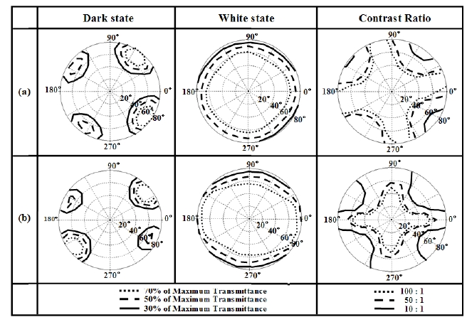
Figure 5 shows the viewing angle characteristics of the proposed transflective display using the negative dielectric anisotropy of the LC. The uniformity of the white state in both the reflectance and transmittance was excellent, along with a remarkably dark state, where T70, T50, and T30 indicated the relative transmittance with respect to the maximal transmittance. Consequently, the contrast ratio in both the R- and T- regions is larger than 10 and exists over 50° and 70° of the polar angle in all directions, respectively. Hence the device with negative dielectric LC shows equally wide viewing angle performances in both the R- and Tregion.
The electro-optical characteristics of transflective LCD using an FFS mode was investigated when an LC negative dielectric anisotropy is used. The proposed device with optimized pixel electrode width of 8 μm shows a single gap and a single gamma curve. In addition, it shows a higher light efficiency and a wide viewing angle for both the R- and T- regions without using any additional compensation film.