Optical code-division multiple-access (OCDMA) is receiving increased attention due to its potential to enhance information security, simplify and decentralize network control, improve spectral efficiency, and increase flexibility in the granularity of bandwidth that can be provided [1-4]. However, for practical applications, there are several issues to overcome, including low spectral efficiency, large multiuser access interference (MAI) as well as others. Spectrally phase coded OCDMA has been studied in detail [4-7] and attempts have been made to overcome these problems. In spectrally phase coded OCDMA, a mode-locked laser produces phaselocked spectral lines, evenly spaced with the pulse repetition rate. These lines are coded by a pseudo-random phase modulation. The random phase coding disturbs the phaselocked feature and spreads the pulse in time, converting the input short pulses into noise like, low intensity signals. In a receiver, the same coder is used to recover the original phase, and the noise-like signal is converted back to the original pulse signal, while waveforms from other users (i.e., MAI noise) which use different codes retain phasedisturbed, low-intensity, noise-like waveforms, which are very similar to the coded signals [4-7]. This means that decoding of a random phase coded waveform simply returns to a random coded waveform set unless the decoding is matched to the pulse. Similar characteristics of the spectrally phase coded OCDMA have been used also for code translation [8]. Therefore, the contrast ratio between the (matched) target signal and (unmatched) MAI noise, which is a measure of system performance, can be simply determined by the ratio between the input pulse and the coded waveforms [9]. To increase this ratio, a large number of spectral chips is required. Results of greater than 20 dB contrast ratio have been obtained by spectral phase coding of ultrashort pulses (broad band with bandwidth W) [4, 5, 9]. Having a high contrast ratio enables us to increase the total number of users (N), enhancing the spectral efficiency. However, too many users in a single channel induce system performance degradation due to overlap between multiuser signals in the time domain [5]. To reduce this degradation we can divide the wide spectral band W into M narrow band (with the spectral window B =
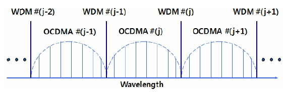
Then we implement L user OCDMA for each narrow band (NB) spectral group, introducing a potential for wavelength division multiplexing (WDM) of OCDMA channel groups. Small (but greater than N/M) user number L can reduce the probability of user signal overlap in time and increase the spectral efficiency. For example, a 20×10 Gb/s (N=20) broad band (BB) OCDMA system with W=16 nm can be divided into 20 channel groups (M=20) of 4×10 Gb/s (L=4) NB-OCDMA systems with B=0.8 nm. The probability of the signal overlap at the above NB-OCDMA receiver can be reduced up to 1/5, whereas the spectral efficiency can increase up to 4 times, compared with those of a BB-OCDMA. Recently, Etemad et al. studied this NB-OCDMA, where 16 spectral lines within the 80 GHz bandwidth were coded for 4×2.5 Gb/s and 6×5 Gb/s OCDMA systems, and they achieved spectral efficiencies of 0.125 bit/Hz and 0.375 bit/Hz respectively [6, 7]. However, the relatively good efficiency of 0.375 bit/s in [7] was achieved by an additional polarization multiplexing, which reduces the significance of the value to half (0.1875 bit/s). Further improvement of the spectral efficiency can be achieved by reducing the number of spectral lines while increasing the speed of each OCDMA channel, and by multiplexing with a signal which has other modulation formats. For example, we can imagine a WDM/OCDMA hybrid transmission, whose spectral allocation is schematically shown in Fig. 1. The OCDMA channels can be implemented by passing mode-locked short pulses through an arrayed waveguide grating (AWG), while the WDM channels are implemented by passing through a high finesse Fabry-Perot interferometer. In practice, ITU DWDM signals with 100 GHz spacing and multichannel NB-OCDMA signals within 100 GHz spectral window groups can be transmitted together through a single fiber.
In this work, as a preliminary study of our idea, we will use 9 spectral lines spaced at 10 GHz (i.e., pulse repetition frequency frep=10 GHz) within a 100 GHz spectral window, ensuring compatibility with conventional ITU DWDM networks, and we will show successful spectrally phase coded waveform discrimination for 4 user 10 G pulse/sec OCDMA. Our NB-OCDMA itself (without polarization multiplexing and/or hybrid transmission with DWDM) has a potential spectral efficiency of 0.4 bit/Hz (3.2 times of [6]). Due to narrow bandwidth, the number of available spectral chips becomes small and a relatively low contrast ratio between the signal and MAI noise is expected. To optimize this contrast ratio, we need to maximize the number of spectral chips, and this we do by setting the individual spectral chips matched one-to-one with individual spectral lines, allowing spectral line-by-line coding of 9 spectral lines. Note that both coded and uncoded waveforms repeat with period T=1/frep, but a random phase coded waveform spans the full time period T while the uncoded pulse is isolated in time. Here we expect uncoded signal pulses with ~10 ps temporal and ~50 GHz spectral widths within a 100 GHz spectral window. The narrow spectral width, leading to a relatively broad signal pulse, allows us to use a simple electrical threshold based on a photo-detector for signal discrimination from MAI noise, without the need for a nonlinear optical hard-limiter where the second harmonic MAI noise is enhanced due to overlap between the signal and MAI waveforms [5]. Therefore, our NB-OCDMA has a distinct advantage at the receiver in addition to its high spectral efficiency.
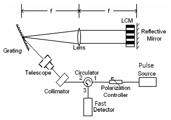
To spread the coded waveform to be as broad and flat as possible within the time period T, we need to manipulate independently the phase of the 9 individual spectral lines (line-by-line spectral phase coding). For the line-by-line spectral phase coding, we build a well-known Fourier Transform pulse shaper coder [5, 10] based on a liquid crystal modulator (LCM) array with 128 pixels of 100 ㎛ each, as shown in Fig. 2. The individual pixels can be electrically controlled to give a random phase shift and intensity modulation. Even though the phase modulation is enough for our OCDMA coding, the intensity modulation is also applied to prepare a NB-OCDMA pulse source with ~50 GHz bandwidth within a 100 GHz spectral window. The OCDMA coder has a reflective geometry where input and output are separated via an optical circulator. A polarization controller (PC) is used to get maximum diffraction performance at the 1200 grooves/mm diffractive grating. Since the spectral resolving power of the grating is proportional to the size of the beam spot on it, a fiber pigtailed collimator and subsequent telescope magnify the input beam size to 16-mm diameter. Discrete spectral lines of the input short pulse are diffracted by the grating and focused by the lens with 1-m focal length. The LCM array placed just before the focal plane independently controls both intensity and phase of the spectral components falling on the LCM. A retroreflecting mirror returns the modulated spectral lines to a fiber, allowing them to exit through an optical circulator.
From the Fourier transform configuration, we can easily arrive at the following relationship between the wavelength (Δλ) and the spatial (Δx) separations for the first order diffracted light.
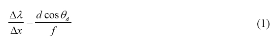
where d is the grating constant, θd the grating diffraction angle, and f the lens focal length.
We adjusted the diffracted (
Now we can get the beam radius w0 of the coder at the LCM (
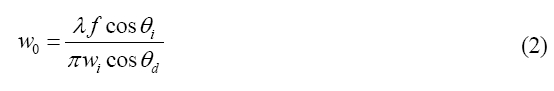
where λ is the wavelength, θi the grating incident angle, and wi the incident beam radius.
The spectral resolution of the coder can be defined as the spectral width corresponding to beam diameter 2w0. Our system shows the focused beam diameter of ~65 ㎛, corresponding to the spectral resolution of ~3 GHz, which is high enough to control accurately the phase and intensity of individual spectral lines spaced at 10 GHz. Finally, the temporal waveforms and optical spectra are measured by a fast 50 GHz sampling scope coupled with a fast (60 GHz) photo-detector and an optical spectral analyzer with0.01 nm resolution, respectively.
III. EXPERIMENTAL RESULTS AND DISCUSSION
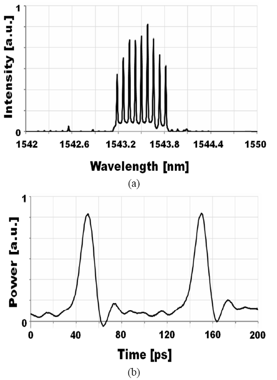
To select 9 phase locked spectral lines within a 100 GHz spectral window from a frequency comb constituting of short pulses at 10 GHz repetition rate, we program the pixels of the LCM in Fig. 2 such that 9 lines are allowed and the rest are blocked. The intensity of the allowed spectral lines is adjusted to imitate an AWG-passed envelope (i.e., an OCDMA channel in Fig. 1). Fig. 3 shows the optical spectrum and sampling scope trace of the pulse source prepared for our NB-OCDMA coding. Only 9 spectral lines within a 100 GHz spectral window and their AWG-passed like intensity envelope are shown in Fig. 3(a). Due to the limited bandwidth (50 GHz) of our measurement system the pulse width is slightly broadened from 10 ps to 15 ps, but most of its power is well confined within a narrow time interval of ~20 ps within the period of 100 ps, as shown in Fig. 3(b). This indicates that an electrical receiver with a commercially available 50 GHz photo-detector will be good enough for the suggested NB-OCDMA to discriminate the signal from MAI noise, as long as the MAI noise waveforms spread well within the time period. After the intensity adjustment, the individual spectral lines are coded by pseudorandom binary phase.
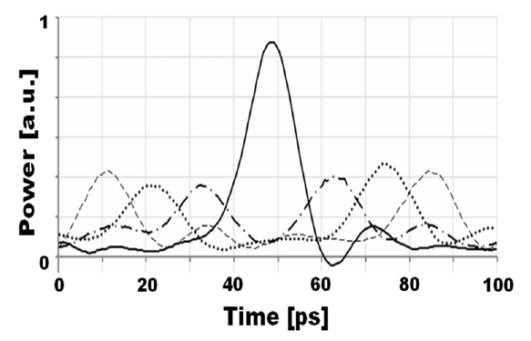
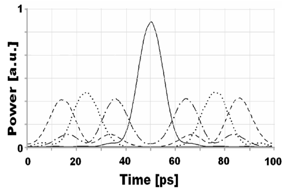
Here we emulate a 4 user OCDMA system; an uncoded pulse signal and 3 of coded MAIs. To form the MAI waveforms, we apply pseudorandom binary phase shift for each of the 9 spectral lines (or chips) as follows; code #1 = [0, π, π, 0, 0, 0, 0, π, π], code #2 = [0, π, 0, 0, π, π, 0, 0, π], and code #3 = [0, π, 0, 0, π, 0, π, π, 0]. Since the phase shift does not affect the intensity, no noticeable change in optical spectra is observed. However, temporal MAI waveforms (measured by a 50 GHz sampling scope) change dramatically, as shown in Fig. 4. To show the waveforms in detail we trace individual waveforms for a single period (100 ps). Individual coded MAI waveforms spread differently in time but show similar low intensity characteristics to be easily discriminated from the target pulse signal shown in Fig. 3(b).
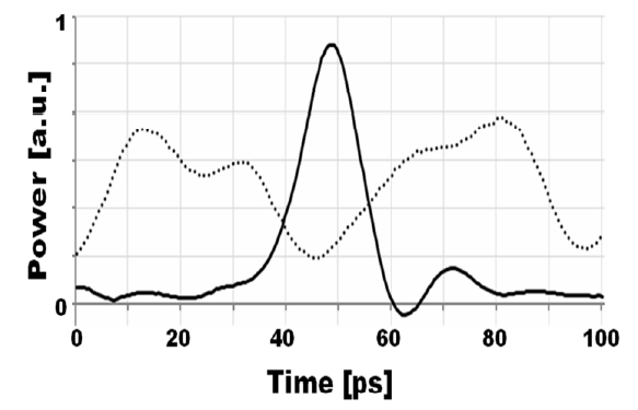
To examine the worst case where all MAI waveforms exist, we compare the uncoded pulse signal with the sum of 3 coded MAI waveforms, as shown in Fig. 5 (no interference between the signal and/or MAI waveforms was assumed). Unfortunately, Fig. 5 shows that asynchronous detection may not be applicable for the NB-OCDMA, since the peak signal to MAI ratio becomes very poor depending on timing of individual MAI waveforms. However, if we use time coordinated synchronous detection [11] at the original pulse position (around time
To confirm our result through simulation using a photonics simulation package, we generate 9 phase-locked spectral lines corresponding to those in Fig. 3 and perform binary phase coding based on the codes given in the experiment. Fig. 6 shows pulse signal and coded MAI waveforms. Here we assumed an ideal binary phase coder and a 50 GHz photo-detector. Note that the waveforms, especially those which are time spread by the phase coding, are very similar to those of the experiment. Slight differences in the waveforms may be caused by non-ideal devices used in the experiment. The peak signal to total MAI noise ratio becomes similar to that of the experiment, while the signal to MAI ratio at the original pulse position (
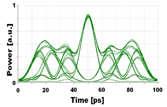
Next we apply pseudorandom pulse modulation for the 4 user 10 Gb/s NB-OCDMA and examine its eye diagram, as shown in Fig. 7. Again we ignore the interference between the pulse signal and/or MAI waveforms, and assume a time coordinated synchronous detection in the receiver. Clear eye-opening is observed around the original pulse position, as expected in Fig. 6.
The good agreement between the experiment and simulation enables us to examine the performance of various spectralphase coding algorithms for a given number of spectrallines through simulation (without experiment) and to findan optimum code family with maximum temporal spreadbut minimum overlap among users.
We performed a feasibility study of NB-OCDMA whichhas a potential for high spectral efficiency by allowing alarger number of users and by providing compatibility withconventional ITU DWDM networks. For OCDMA phasecoding we built a high resolution line-by-line spectral coderwith ~3 GHz of spectral resolution, which is capable ofcontrolling accurately the phase and intensity of individualspectral lines with 10 GHz spacing. Based on the line-bylinecoder, only 9 phase-locked, 10 GHz spaced, spectrallines within a 100 GHz spectral window (corresponding tothe ITU DWDM channel spacing) were prepared for our NBOCDMAfrom a 10 GHz short pulse source. Next weapplied pseudorandom binary phase on the prepared spectrumto generate 3 MAI waveforms. For the uncoded pulsesignal discrimination from the MAI noise, we used a simpleelectrical receiver (~50 GHz bandwidth) with a commerciallyavailable fast photo-detector. Even thought an asynchronousreceiver might not be applicable to our NB-OCDMA, considerablyhigh contrast ratio of ~5 between the target signaland MAI noise could be achieved at the time coordinatedsynchronous receiver. Further improvement in the contrastratio would be possible by more deliberate phase controlof the spectral lines. Simulations using a photonics packageagreed well with the experiments, proving the validity ofthe suggested idea. In this way, we demonstrated binaryspectral phase coded waveform discrimination for 4×10 Gpulse/sec NB-OCDMA via direct electrical detection. Potentialspectral efficiency of the suggested system was 0.4 bit/Hzand would increase up to 1 bit/Hz by polarization multiplexingand hybrid transmission with ITU DWDM signals.