검색 전체 메뉴
PDF
맨 위로
OA 학술지
Visual Quality Enhancement of Three-Dimensional Integral Imaging Reconstruction for Partially Occluded Objects Using Exemplar-Based Image Restoration
  • 비영리 CC BY-NC
  • 비영리 CC BY-NC
ABSTRACT
Visual Quality Enhancement of Three-Dimensional Integral Imaging Reconstruction for Partially Occluded Objects Using Exemplar-Based Image Restoration
KEYWORD
Integral Imaging , Image restoration , Computational reconstruction
  • I. INTRODUCTION

    Integral imaging is a three-dimensional imaging technology that can provide full parallax and continuous viewing points [1]. More notably, integral imaging provides naturally colored images without the use of any special glasses [2]. Since integral imaging was first proposed in 1908, it has drawn a great deal of attention from researchers [3-7]. To implement three-dimensional imaging and display, integral imaging systems require multiple perspectives on three-dimensional objects. These recorded perspective images are called elemental images, each of which plays an important role in integral imaging.

    Real-world scenes have complex arrangements of objects with multiple occlusions. Occlusions can be present in all but the most constrained environments. In the digital image processing field, researchers often consider the occluded region to be a missing region and use imaging restoration methods to restore the missing region [8-15]. The most representative method in [8] is the exemplar-based image restoration algorithm; however, depth information is not considered in this method. In attempts to expand upon previous research, one pixel restoration method was proposed in a computational integral imaging system [16] to address this depth problem. In this method, some of the invisible pixels of the occluded target region in an elemental image can be restored by using the corresponding visible pixels from the others due to different perspectives on the elemental images. However, if the foreground object happens to be located very close to the occluded target, it can cause major information loss of the target object in the elemental images. It is difficult to reconstruct the occluded target region with such limited information. Therefore, this pixel restoration method can be affected by the distance between the occluded target object and the foreground object.

    In this paper, we propose an image restoration method to overcome the limitation of the distance between the occluded target object and the foreground objects. In the proposed method, a minimum spanning tree (MST) is used to estimate the occluded target region of each elemental image, and these occluded target regions are marked based upon the estimated depth maps. Then the proposed pixel restoration method is used to fill in the region left behind after occlusion removal. Our method combines the exemplar-based image restoration algorithm with the pixel restoration scheme to enhance the visual quality of three-dimensional integral imaging reconstruction for partially occluded objects. In Section II, the traditional image restoration methods are reviewed. The proposed method is presented in Section III. In Section IV, we report on carrying out several experiments and confirming the feasibility of our method. Finally, we conclude this paper in Section V.

    II. REVIEW OF PIXEL RESTORATION SCHEMES

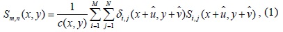
    In previous works, several methods have been suggested to solve the occlusion problem [16-18]. Most approaches have attempted to develop specific image processing algorithms based on statistical or contour analysis to alleviate the occlusion problem. Besides the image processing algorithms, another method was proposed in which the occluded target region was directly removed for visibility-enhanced reconstruction [17]. However, in this approach, the vacant target area caused by occlusion removal may lead to visual quality degradation of the reconstructed target image. To overcome this problem, Piao et al. [16] proposed an effective approach for visibility-enhanced recons-truction of a partially occluded three-dimensional scene by using the pixel-restoration method in a computational integral imaging system. This scheme can be expressed as follows:

    image
    image
    image

    where,Sm,n(x,y) is the pixel located at the position of (x, y) in elemental image Sm,n (x, y). is the disparity between, Sm,n (x, y) and its corresponding pixel in Si,j, which can be obtained from the disparity map in [19]. In synthetic aperture integral imaging, the elemental image array is assumed to be M×N elemental images.

    As is described in Section I, the pixel restoration scheme depends on the distance between the occluded target region and the foreground objects. By analyzing whether the distance d between the occluded target regions and the foreground objects is less than Δdmin, those target regions cannot be completely reconstructed due to the effect of the foreground objects. Δdmin is defined as follows:

    image

    Where do is the distance between the lenslet array and the occluded target region, and dc is the distance between the lenslet array and the foreground objects. lc is the size of the occluding object, p is the pitch of the lenslet, and n is an index number defined in our previous work [16].

    III. THE PROPOSED METHOD

    In synthetic aperture integral imaging, every elemental image represents a slightly different viewpoint on a three-dimensional scene. Thus a number of invisible pixels of the occluded region of an elemental image viewed from one viewpoint may be visible in other elemental images due to their viewpoint differences. As is shown in the above description, using a pixel restoration scheme can restore a partially occluded region, but it fails for the region where the distance between the occluded target region and the foreground objects is less than Δdmin. We introduce a new image restoration method in synthetic aperture integral imaging in which all the missing pixels of the occluded region in each elemental image can be restored by finding the best patches from the others.

      >  A. MST-Based Stereo Matching

    In previous work, a depth estimation method using MST-based stereo matching in integral imaging was proposed to detect occlusions; it is suitable for both simple and complex three-dimensional scenes [19].

    Zhong et al. [19] presents a non-local stereo matching method that can produce an accurate disparity map between two elemental images. According to the principle of measurement by triangulation, the disparity map can be transformed to a depth map, and we can use the depth map to detect the occlusions. In [19], the reference elemental image In (n = 1,...,N) is represented as a connected, undirected graph G = (V, E), where each node in V corresponds to a pixel in In, and each edge in E connects a pair of neighboring pixels. In [19], the first elemental image is selected as the reference image and a MST T is constructed from G. A non-local aggregated cost is computed as follows:

    image

    where Cd is the matching cost, Dis (p, q) is the sum of the edge weights along the path (that is, the shortest path) between any two pixels p and q. σ is a user-specified parameter for distance adjustment, which is often set to be 0.1. The disparity at pixel p could be obtained by finding the minimum matching cost.

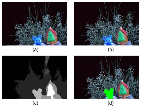
    Fig. 1(a) and (b) show the input elemental images used to extract the disparity map, Fig. 1(c) shows the disparity map that is generated by the non-local aggregation with non-local refinement. Fig. 1(d) shows the occlusion detection results of the first elemental images, which is replaced with a green color.

      >  B. Image Restoration Scheme

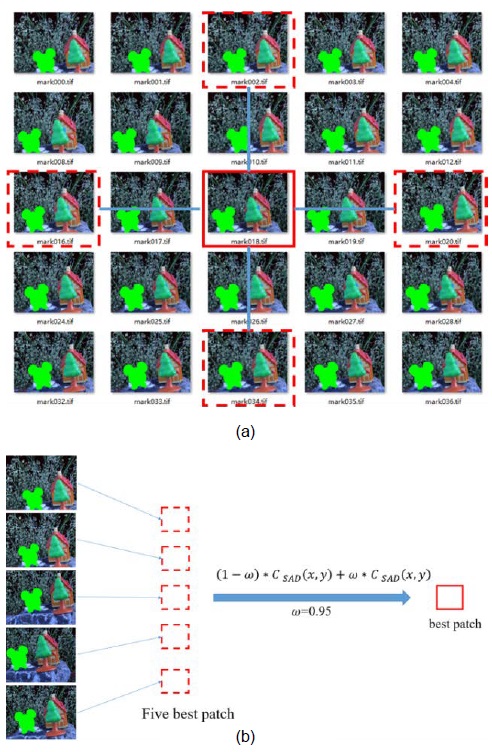
    As shown in Fig. 2, five elemental images are selected as the source region. As shown in Fig. 2(a), we find the best patch from the source region to restore the missing region, which is enclosed by a solid red rectangle. The principle for selecting the elemental images is defined in Eq. (12).

    1) Computing Patch Priorities

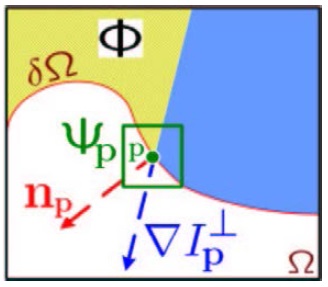
    The filling order is crucial to non-parametric texture synthesis, and designing a fill order that explicitly encourages propagation of linear structure together with texture should produce a better image restoration [8]. Criminisi’s work performs this task through a best-first filling algorithm that depends entirely on the priority values that are assigned to each patch on the fill border. As shown in Fig. 3, we define the priorities for each point to determine the filling order.

    For each point pδΩ, its priority Pi,j (p) is defined as follows:

    image

    where the subscript i, j represents the ith row and jth column of the image in a synthetic aperture integral imaging system.

    We call Confi,j (p) the confidence term and Di,j (p) the data term, and they are defined as follows:

    image
    image

    where, |ψi,j P| is the area of ψi,j P as shown in Fig. 3, α is a normalization factor, np is a unit vector orthogonal to the border δΩ going through point p, and is the isophote at point p. During initialization, the function Confi,j (p) is set to Confi,j (p) = 0 ∀p ∈ Ωi,j, Confi,j (p) = 1∀p ∈ Φi,j.

    2) Propagating Texture and Structure

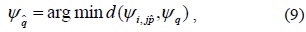
    Once all priorities on the fill border have been computed, the patch with highest priority is found. We use Eq. (9) to find the most similar patch to fill the patch

    image

    where ψq ∈ {Φi,j, Φ0,j, Φi,0, ΦM,j, Φi,N}, M×N is the number of the elemental image in the synthetic aperture integral imaging method; in fact, as shown in Fig. 2(b), two steps are implemented to find the most similar patch:

    In step 1, we find the five best patches {ψi,j, ψ0,j, ψi,0, ψM,j, ψi,N} from the five selected elemental images by using the dissimilarity measurement of the sum of squared intensity differences (SSD):

    image

    where m, n is the size of the patch and ψq, px,y and qx,y is the corresponding pixel’s value in and ψq.

    In step 2, we find the most similar patch from the five best patches by combining the SSD and a gradient-based measure (GRAD):

    image
    image

    where ψq = {ψi,j, ψ0,j, ψi,0, ψi,0, ψi,N}, ∇px,y and ∇qx,y is the corresponding pixel’s gradient value in and ψq. ω is an equilibrium factor, in our experiment, ω = 0.05.

    3) Updating Confidence Values

    After the patch has been filled with new pixel values, the confidence Ci,j (p) is updated in the area delimited by as follows:

    image

    Repeat the above steps, until the whole region is filled. Ultimately, we achieve the image in which the occlusion is removed, as shown in Fig. 4.

    4) Filling Order Control Using a Structure Tensor

    The exemplar-based image restoration algorithm performs well in filling large missing regions. However, discontinuous structures can be problematic, and these discontinuous structures will influence patch priorities.

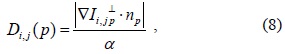
    In view of this problem, we use the structure tensor to recompute the data term in Eq. (8) [20].The structure tensor is also referred to as the second-moment matrix. It summarizes the predominant directions of the gradient, and the degree along those directions. The structure tensors Ji,j are defined as follows:

    image

    where Kρ is the normal kernel and ρ is the variance of Kρ, ⊗ represents the cumulative operation, and * represents the Gaussian convolution operation.

    Eq. (8) can be replaced as follows:

    image

    where div is the divergence operator.

    We also modify the priority Pi,j (p) in Eq. (6) as follows:

    image

    where α, β is the adjustment coefficient and α + β = 1.

    IV. EXPERIMENT AND DISCUSSION

    In this section, image restoration and three-dimensional image reconstruction in a synthetic aperture integral imaging system is implemented. The distance between the building and the pickup devices is approximately 20 m, and a toy human figure is located at approximately 1 m from the pickup devices. The camera in use has an image sensor array of 2400×1600 pixels, and each pixel size is 8.2 μm. In order to improve the operation speed, every elemental image is resized to 480×320 pixels. The moving step of the camera is Δd = 2 mm.

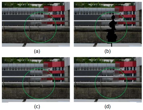
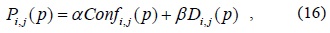
    As shown in Fig. 5, the occlusion regions are marked as a green circle by using MST-based stereo matching, the image restoration algorithm used for the marked region. The result of Criminisi’s algorithm is shown in Fig. 5(a); we found that some errors occurred, which are marked by green circles. In our experiment, some errors exist in almost every restored element image, and these errors will reduce the visual quality of the reconstructed images. Fig. 5(b) shows the result proposed in [16]. It can be seen that only partially occluded regions are restored. This is because the distance between the occluded target region and the foreground objects is less than Δdmin. Fig. 5(c) shows the restored elemental image by using the proposed method without the structure tensor . Compared to Fig. 5(a), there are fewer errors occur in the fill regions, in which improving the visual quality of the reconstructed images significantly. Fig. 5(d) shows an improved algorithm for image restoration based on additional structure tensor in synthetic aperture integral imaging. Compared to Fig. 5(c), the error fill regions are further reduced. We have demonstrated that the proposed method remains robust when large regions need to be restored.

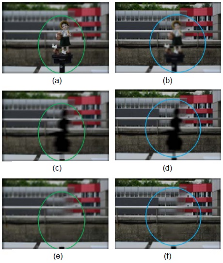
    Fig. 6 illustrates two sets of images reconstructed with the computation integral imaging reconstruction technique at the distance of 500 mm and 760 mm. Fig. 6(a) and (d) show the images reconstructed at Z = 500 mm and Z = 760 mm by using originally captured elemental images, and Fig. 6(b) and (e) show the images reconstructed using the occlusion removal method in [16] at Z = 500 mm and Z = 760 mm. Fig. 6(c) and (f) show the reconstructed 3D images by using the proposed method.

    In the comparisons shown in Fig. 6(a)–(f), we were easily able to show that the visual quality of the reconstructed images is improved by using the proposed restoration method. Fig. 6(f) shows the reconstructed image, in which the restoration region is marked with a green circle. Even though blurring occurs in a small region of the reconstructed image due to missing depth information, the proposed method outperforms the one in [16] in terms of visual quality. We are continuing to develop extensions of the proposed method to address the issue of the missing depth information.

    V. CONCLUSIONS

    In this paper, we proposed an exemplar-based image restoration method to solve the occlusion problem in synthetic aperture integral imaging. Our proposed method successfully overcame the limitation of the distance between the target and the occluding object. Experimental results confirm the feasibility of the restoration method when applied to three-dimensional image reconstructions. However, some depth information is missed by use of our method. In future works, we intend to extend the proposed method to address the issue of missing depth information.
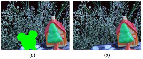
참고문헌
  • 1. Lippmann G. 1908 “La photographic integrale,” [Comptes Rendus de l'Academie des Sciences] Vol.146 P.446-451 google
  • 2. Lee J. J., Lee B. G., Yoo H. 2011 “Depth extraction of three-dimensional objects using block matching for slice images in synthetic aperture integral imaging,” [Applied Optics] Vol.50 P.5624-5629 google cross ref
  • 3. Jang J. S., Javidi B. 2002 “Three-dimensional synthetic aperture integral imaging,” [Optics Letters] Vol.27 P.1144-1146 google cross ref
  • 4. Stern A., Javidi B. 2003 “3-D computational synthetic aperture integral imaging (COMPSAII),” [Optics Express] Vol.11 P.2446-2451 google cross ref
  • 5. Hong S. H., Jang J. S., Javidi B. 2004 “Three-dimensional volumetric object reconstruction using computational integral imaging,” [Optics Express] Vol.12 P.483-491 google cross ref
  • 6. Jang J. Y., Ser J. I., Cha S., Shin S. H. 2012 “Depth extraction by using the correlation of the periodic function with an elemental image in integral imaging,” [Applied Optics] Vol.51 P.3279-3286 google cross ref
  • 7. Arimoto H., Javidi B. 2001 “Integral three-dimensional imaging with digital reconstruction,” [Optics Letters] Vol.26 P.157-159 google cross ref
  • 8. Criminisi A., Perez P., Toyama K. 2004 “Region filling and object removal by exemplar-based image restoration,” [IEEE Transactions on Image Processing] Vol.13 P.1200-1212 google cross ref
  • 9. Komodakis N. 2006 “Image completion using global optimization,” [in Proceedings of IEEE Computer Society Conference on Computer Vision and Pattern Recognition] P.442-452 google
  • 10. Sun J., Yuan L., Jia J., Shum H. Y. 2005 “Image completion with structure propagation,” [ACM Transactions on Graphics] Vol.24 P.861-868 google cross ref
  • 11. Huang T., Chen S., Liu J., Tang X. 2007 “Image inpainting by global structure and texture propagation,” [in Proceedings of the 15th International Conference on Multimedia] P.517-520 google
  • 12. Zhou H., Zheng J. 2010 “Adaptive patch size determination for patch based image completion,” [in Proceedings of 17th IEEE International Conference on Image Processing] P.421-424 google
  • 13. Liu Y., Tian X. J., Wang Q., Shao S. X., Sun X. L. 2010 “Image inpainting algorithm based on regional segmentation and adaptive window exemplar,” [in Proceedings of 2010 2nd International Conference on Advanced Computer Control (ICACC)] P.656-659 google
  • 14. Wu J., Ruan Q. 2006 “Object removal by cross isophotes exemplar-based inpainting,” [in Proceedings of 18th International Conference on Pattern Recognition (ICPR)] P.810-813 google
  • 15. Telea A. 2004 “An image inpainting technique based on the fast marching method,” [Journal of Graphics Tool] Vol.9 P.25-36 google
  • 16. Piao Y., Zhang M., Kim E. S. 2012 “Effective reconstruction of a partially occluded 3-D target by using a pixel restoration scheme in computational integral-imaging,” [Optics and Lasers in Engineering] Vol.50 P.1602-1610 google cross ref
  • 17. Hong S. H., Javidi B. 2005 “Three-dimensional visualization of partially occluded objects using integral imaging,” [Journal of Display Technology] Vol.1 P.354-359 google cross ref
  • 18. Piao Y., Kim E. S. 2011 “Performance-enhanced recognition of a far and partially occluded 3-D object by use of direct pixel-mapping in computational curving-effective integral imaging,” [Optics Communications] Vol.284 P.747-755 google cross ref
  • 19. Zhong Z., Piao Y., Qu H., Zhang M. 2015 “MST-based occlusion detection in synthetic aperture integral imaging,” [in Proceedings of 2015 OSA Imaging and Applied Optics Congress: Imaging and Applied Optics] google
  • 20. Liu K., Su B. T., Wang Y. B. 2012 “Improved algorithm of exemplar-based image inpainting,” [Computer Engineering] Vol.38 P.193-195 google
이미지 / 테이블
  • [ ] 
  • [ ] 
  • [ ] 
  • [ ] 
  • [ ] 
  • [ Fig. 1. ]  (a) The first elemental image. (b) The second elemental image. (c) Disparity map produced from MST-based stereo matching. (d) Occlusion detection.
    (a) The first elemental image. (b) The second elemental image. (c) Disparity map produced from MST-based stereo matching. (d) Occlusion detection.
  • [ Fig. 2. ]  (a) Five elemental images are selected as exemplar images to restore the elemental image, which is enclosed by a solid rectangle. (b) The best patches are selected from the five elemental images.
    (a) Five elemental images are selected as exemplar images to restore the elemental image, which is enclosed by a solid rectangle. (b) The best patches are selected from the five elemental images.
  • [ Fig. 3. ]  Notation diagram. Ω is the removed region and its contour is δΩ, Φis the source region that was not removed. The patch ψp centered on the point p ∈ δΩ is the region to be filled.
    Notation diagram. Ω is the removed region and its contour is δΩ, Φis the source region that was not removed. The patch ψp centered on the point p ∈ δΩ is the region to be filled.
  • [ ] 
  • [ ] 
  • [ ] 
  • [ ] 
  • [ ] 
  • [ ] 
  • [ ] 
  • [ ] 
  • [ Fig. 4. ]  Image restoration in synthetic aperture integral imaging. (a) The mask marked in green. (b) The occlusion removed from the elemental image.
    Image restoration in synthetic aperture integral imaging. (a) The mask marked in green. (b) The occlusion removed from the elemental image.
  • [ ] 
  • [ ] 
  • [ ] 
  • [ Fig. 5. ]  Restored elemental images using (a) algorithm in [8], (b) algorithm in [16]. (c) The proposed method. (d) The proposed method with a structure tensor.
    Restored elemental images using (a) algorithm in [8], (b) algorithm in [16]. (c) The proposed method. (d) The proposed method with a structure tensor.
  • [ Fig. 6. ]  Reconstructed 3D images at (a)?(c) Z = 500 mm, (d)?(f) Z = 760 mm.
    Reconstructed 3D images at (a)?(c) Z = 500 mm, (d)?(f) Z = 760 mm.
(우)06579 서울시 서초구 반포대로 201(반포동)
Tel. 02-537-6389 | Fax. 02-590-0571 | 문의 : oak2014@korea.kr
Copyright(c) National Library of Korea. All rights reserved.