The vibration sensitivities of optical cavities depending on the support area were investigated, both numerically and experimentally. We performed numerical simulations with two models: one with total constraint of the support area, and the other with only vertical constraint. An optimal support condition insensitive to the support’s area could be found by numerical simulation. The support area was determined in the experiment by a Viton rubber pad. The vertical, transverse, and longitudinal vibration sensitivities were measured experimentally. The experimental result agreed with the numerical simulation of a sliding model (only vertical constraint).
Narrow-linewidth lasers are essential tools for various applications, including optical clocks [1-4], low-phase-noise microwave generation [5], fundamental tests of relativity [6], gravitational-wave detection [7], and dark matter searching [8, 9]. The laser linewidth is narrowed usually by stabilizing its frequency on an ultrastable optical cavity resonance. Because such an optical cavity is sensitive to external vibrational noise, there have been a number of studies during the last decade on support methods to minimize the sensitivity of both horizontal cavities [10-14] and vertical ones [15, 16], and the frequency stability of lasers reached the thermal noise limit, which is given by the Brownian noise from mirror coatings, mirror substrates, and cavity spacers [12, 16]. To decrease the thermal-noise limit further [17], researches are being actively undertaken with longer cavities [17-21], with cavities at cryogenic temperatures [22, 23], or using new materials with lower mechanical loss [24]. However, longer cavities are generally more sensitive to vibrational noise, and their frequency stabilities are still limited by seismic noise [21]. Thus, more works are required in reducing the vibration sensitivity of optical cavities.
For the clock lasers of the Yb optical lattice clock at KRISS (Korea Research Institute of Standards and Science) [25-27], cutout-type vibration-insensitive horizontal optical cavities were adopted [11, 12]. Optimal cavity support positions with the smallest vibration sensitivity can be determined by numerical simulations before the experiments [10-24]. Optical cavities are usually supported by small Viton rubber balls [11, 12, 18, 19, 21]; however, considering that rubber balls can be squeezed, the numerical simulations have limitations in this case, because the support-area sizes are ambiguous and the pressure distribution over the support area is not uniform. With this concern, we used Viton pads instead of balls to support the optical cavity. We performed finite element analysis (FEA) for the vibration sensitivity of our cavities, varying the support’s position and its diameter with a fixed support point (fully constrained) and a sliding support (only vertically constrained). Also, an optimal support condition, insensitive to support area, could be found. We compared these numerical simulations with experimental results.
II. CAVITY DESIGN AND FINITE-ELEMENT ANALYSIS
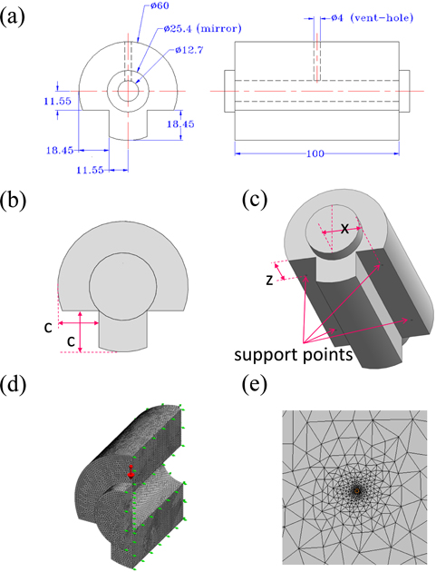
The shape of the cavity (front and side views, with dimensions in mm) in this research is shown in Figs. 1(a) and 1(b), with the definition of the cutout depth
The locations of the support points have to be optimized to minimize the vibration sensitivities [10-24]. Thus, we performed finite element analysis (FEA) to estimate the optimal positions of support points by varying
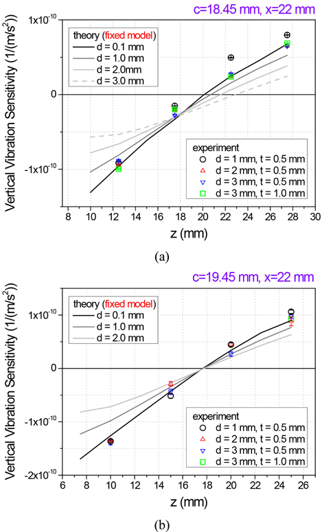
In Fig. 2(a), the FEA result for Cavity1 with the fixed model is shown, for varying
The dependence of the vertical vibration sensitivity on
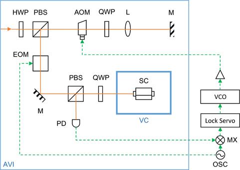
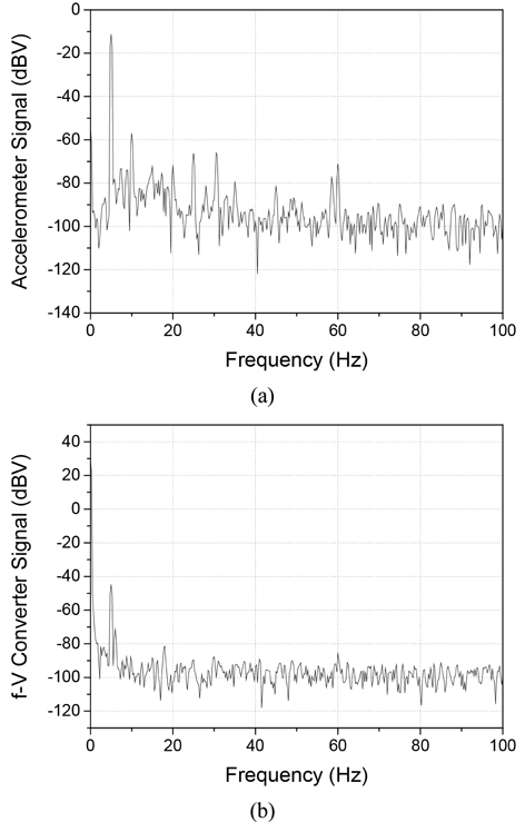
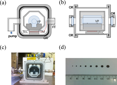
Figure 4 shows the experimental setup for measuring vibration sensitivity. The laser has a wavelength of 578 nm [26, 30, 31], which is a probe laser for the Yb lattice clock transition. The frequency of the input laser in Fig. 4 was stabilized in advance to a resonance of another cavity, which has the same design as Cavity2, by the Pound-Drever-Hall (PDH) method [32]. The frequency of the input laser beam is shifted by a double-pass acousto-optic modulator (AOM) that is driven by a voltage-controlled oscillator (VCO); thus it can be considered an independent laser source, compared to the original input. Then we used a PDH setup to stabilize the laser frequency to a resonance of either Cavity1 or Cavity2, as in Fig. 4. The optical cavity was contained in a vacuum chamber. The PDH error signal was fed back to the VCO for the stabilization. The frequency change due to vibration was measured by the beat note between this stabilized laser and the original input laser. The frequency of this beat-note signal was converted into a voltage using a frequency-to-voltage converter. The vacuum chamber and optical setup were placed on an active vibration-isolation table (AVI) (TS-300/LP, The TableStable Ltd.). The AVI was used in “shaker” mode to provide a sinusoidal acceleration in one of the three orthogonal directions, to measure the vibration sensitivity. The magnitude of the acceleration was measured by a three-axis accelerometer. The frequency of the sinusoidal acceleration was chosen to be 5 Hz, under conditions such that the cavity deformation could be considered to be quasistatic, and the cross coupling among the vertical acceleration and two horizontal (transverse and longitudinal) accelerations was suppressed by more than 20 dB. The magnitudes of the acceleration and the frequency-to-voltage converter’s signal were measured simultaneously, using a spectrum analyzer and by measuring the signals at 5 Hz (Fig. 5). The cavity was supported with four Viton pads (Figs. 6(a) and 6(b)). Pads with various diameters between 1 mm and 5 mm were made using hole punches and 0.5-mm-thick Viton sheets. A picture of the produced Viton pads is shown in Fig. 6(d).
Since we have to open the vacuum chamber frequently to measure the vibration sensitivity at various support points with many kinds of Viton pads, the vacuum chamber’s covers were sealed with O-rings (Figs. 6(a) and 6(b)). The vacuum chamber was made of aluminum, for convenient temperature control by a thermoelectric cooler and a thermistor, which would have advantages in finding the temperature of zero thermal expansion coefficient for the ULE cavity. The size of the vacuum chamber was 188 mm × 188 mm × 204 mm. The windows have coatings that are antireflective at 578 nm. A picture of the vacuum chamber with a cavity is given in Fig. 6(c).
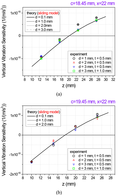
The experimental results for the vibration sensitivity to vertical acceleration for Cavity1 and Cavity2 are shown in Figs. 2(a) and 2(b) respectively, together with the results of numerical simulation with the fixed model. The frequency change was normalized to the optical frequency. Four kinds of Viton pads, with various diameters and thicknesses, were used in the experiments. The vibration sensitivities were measured at four
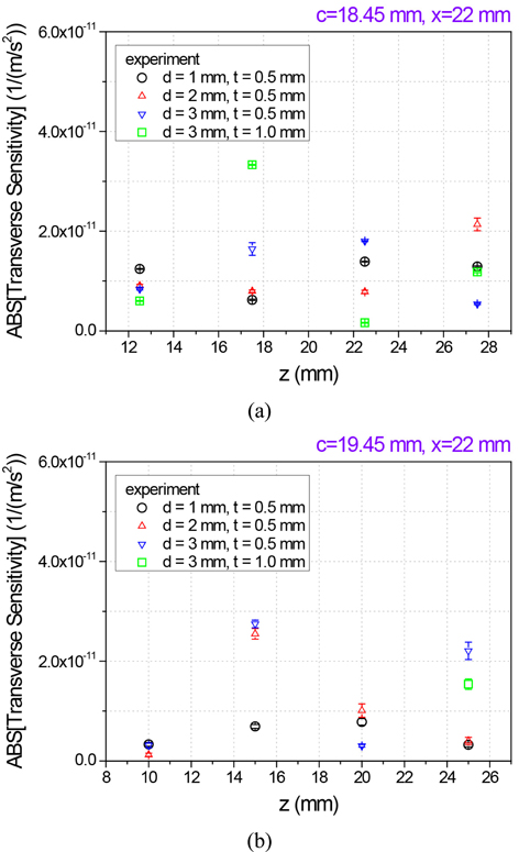
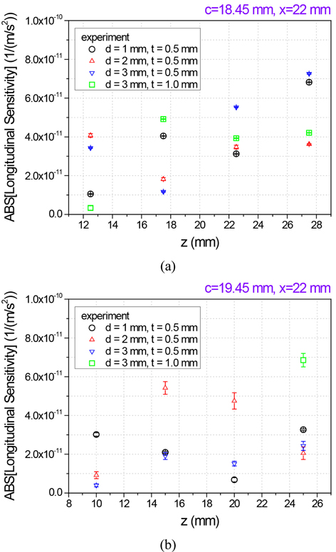
We also measured the horizontal (transverse and longitudinal) vibration sensitivities for both cavities. The transverse direction is along the
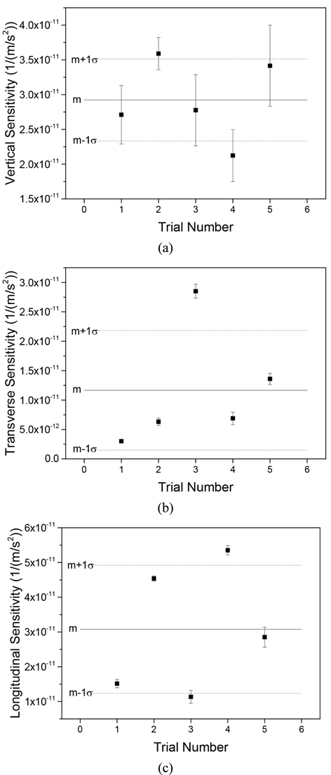
To explain the scattering of the vibration sensitivities, we performed a repeatability test of the measurement. Each of the data points in Fig. 9 was obtained by averaging 10 measurements, and the error bars represent the standard deviations. We obtained five vibration-sensitivity values for each direction under the same conditions (Cavity2,
We investigated the support-area dependence of vibration sensitivities of optical cavities, by numerical simulation and by experiment. Following the simulation results, a new cavity was designed which has a vibration-insensitive support position independent of the support’s area. The numerical simulation was performed with two models: one with total constraint on the support area, and the other with only vertical constraint. The experimental results agreed well with the model based on vertical constraint. The vibration sensitivities in the three orthogonal directions (vertical, transverse, and longitudinal directions) were measured. The scattering of the sensitivity measurements could be explained by the repeatability in the location of the cavity’s support.