We propose a precise 3D endoscopic technique for medical and industrial applications. As the 3D measuring principle, the continuously scanning structured illumination microscopy (CSSIM), which enables to obtain 3D sectional images by the synchronous axial scanning of the target with the lateral scanning of the sinusoidal pattern, is adopted. In order to reduce the size of the probe end, the illumination and detection paths of light are designed as coaxial and a coherent imaging fiber bundle is used for transferring the illumination pattern to the target and vice versa. We constructed and experimentally verified the proposed system with a gauge block specimen. As the result, it was confirmed that the 3D surface profile was successfully measured with 16.1 µm repeatability for a gauge block specimen. In order to improve the contrast of the sinusoidal illumination pattern reflected off on the target, we used polarizing optical components and confirmed that the visibility of the pattern was suitable in CSSIM.
An endoscope is essential for observing the insides of the human body such as stomach and intestines to investigate any kinds of diseases without surgery [1]. It has also been used as an assistant device for a surgeon to look into the surgical area in detail [2]. In addition to medical applications, an endoscope or a boroscope is widely used in industrial fields for measurements and inspections of small defects through small holes [3, 4]. Even though interferometry [5] and microscopy [6] have become representative technologies obtaining 3D surface profile of a target as well as 2D features of a specimen, their typical microscopic configurations are not appropriate when the target is located inside a certain object because of their relatively bulky probes. Therefore, endoscopy or boroscopy is a promising technology to observe a target through a tiny hole in combination with imaging optics in medical and industrial fields because a small size of distal end can go through a small hole and the optical imaging fiber bundle can transfer the image to the imaging device.
Since a typical endoscope acquires 2D images only, however, it cannot provide the height and depth information in the acquired image. To overcome this limitation, several types of the endoscopes have been developed through introducing conventional 3D measurement technologies such as stereoscopy and optical triangulation. A stereoscopic endoscope [7] observes the target with two different sight angles as human eyes do, and it can achieve 3D imaging by the combination of two 2D images. It has the advantage of a large field of view and relatively simple configuration, but the measurement resolution is not so high because it has been developed as an observation tool. An endoscope based on optical triangulation [8] can improve the measurement resolution by the distance of the detection path from the illumination path but increasing the size of the probe is not avoidable. Moreover, the conventional 3D endoscopes have the limitation for measurements of adjacent targets from the distal probes.
On the other hand, the probe of the typical endoscope consists of two fiber bundles for illumination and image detection and the additional motion part to change the position and direction of the probe. The illumination and detection pathways are completely distinguished and the size of the distal probe should increase up to a few tens of millimeters, which limits applications of the endoscope when the target should be measured through an extremely small aperture.
In this investigation, we propose an endoscopic technique for precise 3D imaging for medical and industrial applications. As the fundamental principle of 3D measurements, we adopt the continuously scanning structured illumination microscopy (CSSIM), which enables to obtain 3D sectional images by axial scanning. In order to reduce the size of the distal probe end, the illumination and detection paths are designed as coaxial, and a coherent imaging fiber bundle is used for transferring the illumination pattern to the target and vice versa.
II. 3D ENDOSCOPY BASED ON CSSIM
2.1. Optical Configuration of the 3D Endoscopy
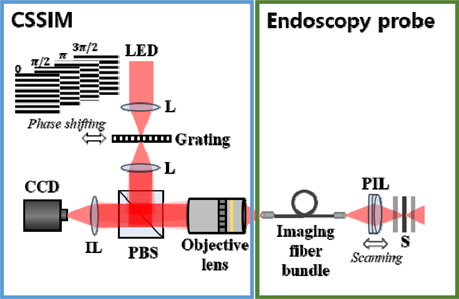
Figure 1 shows the optical configuration of the 3D endoscope proposed in this investigation. It consists of two parts, CSSIM and probe parts. In the CSSIM part, the incoherent light preventing coherent noises such as diffractions and speckles, is illuminated on a sinusoidal amplitude grating or a grid and the structured light pattern is projected on the proximal end surface of the imaging fiber bundle. Then, the structured light is delivered by the flexible imaging fiber bundle and transferred to the sample surface by the imaging lens of the probe part. When the light is reflected off on the target, it returns by the imaging fiber bundle and goes to an imaging device. In this case, the whole system has 5 conjugate image planes; the grid surface, the proximal and distal ends of the imaging fiber bundles, the target surface and the imaging device plane. When the target is located on the best focal position, the structured light pattern can be projected on the target surface clearly and can be seen in the imaging device as well. In the imaging device, the obtained image contains the light pattern and the image of the target surface. When the target is axially moved from the focal position, both the light pattern and the target image are blurred. Therefore, 3D imaging can be achieved by the detection of the highest visibility of the light pattern at each pixel of the imaging device.
2.2. Principle of CSSIM for 3D Surface Profiling
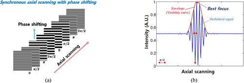
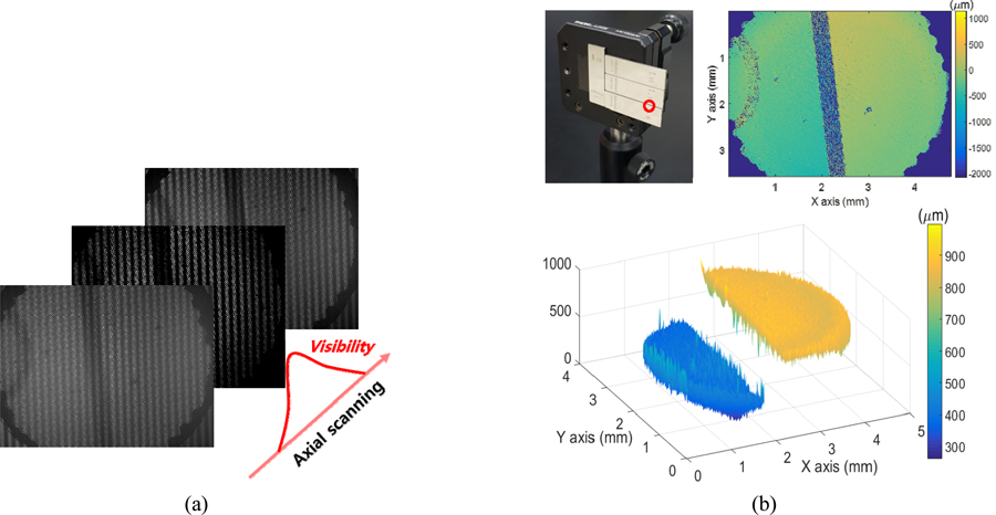
Typically, structured illumination microscopy (SIM) provides topographic surface profile and roughness of a measurement sample similar to those of confocal scanning microscopy although it is a kind of wide field microscopic technique [9, 10]. In SIM, a sinusoidal pattern is projected on the sample surface located in the focal plane and the measurement area can be localized by the pattern. While the measurement sample is scanned axially, the visibility of the illumination pattern is changed and the visibility curve at each pixel can be obtained to determine the peak position. However, the conventional SIM uses phase shifting techniques to extract the visibility curve at a certain axial position and it needs much time to collect phase shifted images for all axial positions. In order to reduce the acquisition time of the image stack, we apply the continuously scanning SIM (CSSIM) [11] instead of the conventional SIM. Axial scanning of the target is synchronized with the lateral scanning of the grid for sinusoidal pattern shifting in CSSIM as shown in Fig. 2(a) to avoid the stop-and-measure procedure of SIM. A single image is obtained at each axial position while the pattern is phase-shifted repeatedly, and then the axial intensities at each pixel becomes modulated by the sinusoidal pattern of the grid as shown in Fig. 2(b). In principle, the peak position of this modulated intensity signal exactly coincides with the peak position of the visibility curve of SIM. Finally, the peak position of the axial intensity signal of CSSIM corresponds to the surface height at each pixel and the surface profile of the sample can be obtained by merging all height information from the imaging device.
In CSSIM, the visibility curve corresponding to the surface height can be extracted from the axial intensity by a Fourier transformation (FT) and an inverse Fourier transformation (IFT) as shown in Fig. 3. A simple mathematical model of the axial intensity signal,

where
where
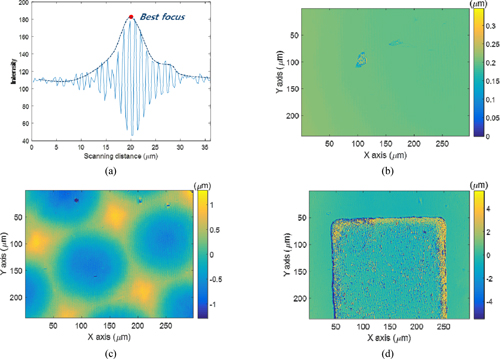
Prior to the verification of the proposed 3D endoscopy, we confirmed the functionalities of CSSIM and probe parts by feasibility tests. In order to validate CSSIM, three kinds of specimens, a plane mirror, a micro-lens array and a rough surface sample were measured with a 20x objective lens. At the location of proximal end of the imaging fiber bundle in Fig. 1, the specimens were put instead of the fiber bundle and axially scanned by a micro stepping motorized stage. As a light source, a white LED was used and a Ronchi grating with 100 µm pitch was selected as the grid for the sinusoidal pattern generation. The target was axially scanned by the motorized stage synchronizing the lateral motion of the grid for phase shifting of CSSIM. Figure 4(a) shows an example of the obtained intensity signal of CSSIM at a single pixel of a CCD camera. The peak position of the visibility was determined by Eq. (2) and the surface profiles of the specimens were successfully reconstructed as shown in Figs. 4(b)~4(d), respectively. In particular, the height of the convex surface for the micro-lens array was calculated as 0.93 µm, similar to the specification provided by the manufacturer (0.87 µm). As seen in Fig. 4(d), a rough surface could also be measured by the CSSIM.
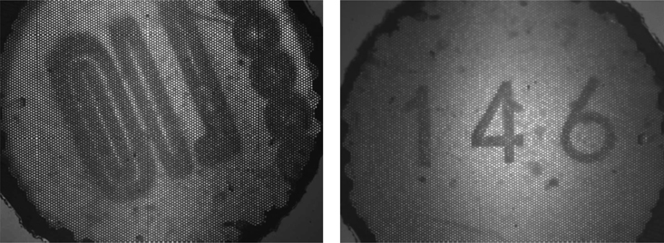
On the other hand, the capability of the imaging fiber bundle was confirmed with the image acquisition of the target in the optical configuration of Fig. 1 without the grid. In this investigation, a coherent imaging fiber bundle (#1533446, Schott) with 0.8 mm effective area which consists of 13,500 fibers was applied. The pixel resolution of the bundle was 8.2 µm. Figure 5 shows the image captured by the CCD camera for the target through the imaging fiber bundle. In this case, 5x objective was used to transfer the light to the fiber bundle because of the suitable field of view (FOV). As shown in Fig. 5, the target was well transferred to the image by the image bundle although the fiber bundle structure appeared slightly in the image.
3.2. Experiments of 3D Endoscopy Based on CSSIM
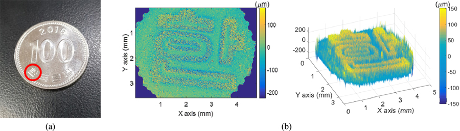
In order to validate the proposed 3D endoscope, the system was constructed as illustrated in Fig. 1 and surface profiles of specimens were measured. As specimens, a gauge block specimen, which consists of two different gauge blocks (1.1 mm and 1.6 mm lengths, Grade 2 with steel) to measure the height difference between them for the estimate of precision or accuracy, and a Korean coin, as an example of a practical sample, were prepared. In the measurement system, a white LED (MWWHLP1, Thorlabs) was used and a Ronchi grating with 200 µm pitch was laterally moved by the micro-stepping motorized stage (XCV630-G-C, Suruga Seiki) with 50 µm steps for 4 bucket phase shifting of the sinusoidal pattern. The pitch of the grid was determined by the relationship of the magnification of the objective lens (5x) and the pixel size of the imaging fiber bundle to avoid the interference between the pattern and the fiber bundle structure. As the imaging lens of the probe, 0.2x imaging lens was designed with the commercial lenses to enlarge the FOV to approximately 4 mm. The specimens were axially scanned by the micro-stepping motorized stage (XCV630-G-C, Suruga Seiki) and the image stack corresponding to synchronous phase shifting of the pattern and axial scanning of the target was obtained.
Figure 6(a) presents an image containing the pattern illumination and the image of the gauge block specimen surface. The sinusoidal pattern was well projected to the target and the target image was imaged to the CCD camera with this illumination pattern. Due to the coaxial configuration of the illumination and imaging paths, the contrast of the pattern in the obtained image is very important to detect the visibility peaks from the image stack. As seen in Fig. 6(a), the sinusoidal pattern is clearly seen and it could be used in CSSIM. The target was axially scanned with 12.5 µm steps with synchronously shifting sinusoidal pattern and the obtained image stack was analyzed. Figure 6(b) shows the reconstructed 3D image of the gauge block specimen, which has two separate regions with different heights where there is no available information in the border because of the steep slopes beyond the limit by numerical aperture (NA) of the probe imaging lens. As the result, the height difference between two regions was measured as 501 µm, slightly deviated from the reference value (500 µm ± 0.9 µm) and the repeatability for the root mean squared value of 15 consecutive measured height maps was 16.1 µm, caused by the motion errors of the axial scanning stage in addition to the intensity fluctuation of the optical source. Figure 7 shows the measurement result of the Korean coin, ‘100 won’. The measurement area was indicated as a red circle with 4 mm diameter as shown in Fig. 7(a) and the 3D surface profile of the area was reconstructed as seen in Fig. 7(b).
3.3. Minimization of Measurement Probe
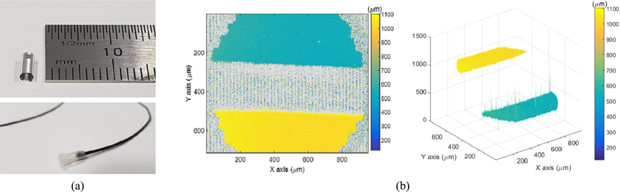
Although the illumination and detection paths were coaxially designed with the imaging fiber bundle to reduce the size of the measurement probe, the bulk probe imaging lens system restricts to minimize the probe size. In order to overcome this limitation, we adopted a GRIN lens with 2 mm diameter as shown in Fig. 8(a) and tested it with the measurements of gauge block specimen. In this case, the 3D surface profile could be measured as shown in Fig. 8(b). The height difference was measured as 496 µm within the measurement uncertainty of the gauge blocks as well.
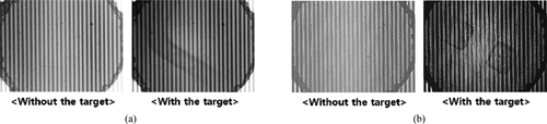
The most important issue of the proposed 3D endoscopy is the possibility of eliminating unwanted sinusoidal patterns reflected on any other surfaces except the target. Among them, the dominant one occurrs via the reflection on the proximal end surface of the imaging fiber bundle. In the experiment, the transmission efficiency of the fiber bundle was less than 28% and most of the light was reflected off on the proximal end surface. As the result, the sinusoidal pattern reflected off the target surface was rarely detected in the CCD camera as shown in Fig. 9(a) compared to the pattern reflected off the fiber bundle surface only. In this investigation, we reduced this unwanted pattern by using polarizing optical components such as a polarizing beam splitter (PBS) and a polarizer as shown in Fig. 1. The initial structured light was horizontally polarized by the polarizer and reflected by the PBS to go toward the fiber bundle. Then, the reflected light on the fiber bundle surface was also reflected by the PBS and could not reach the CCD camera. On the other hand, the reflected light on the target experienced very small birefringence of the fiber bundle twice and was detected by the CCD camera because the imaging fiber bundle is theoretically isotropic but practically not. Therefore, the sinusoidal pattern reflected off the target was detected by the CCD camera as shown in Fig. 9(b), enough to be used in CSSIM, compared to pattern reflected off the fiber bundle surface by the imperfection of the PBS.
Another important concern of the proposed 3D endoscopy is determining the system parameters such as the period of the sinusoidal pattern, the numerical aperture (NA) of objective lens, scanning step size and pixel size of the imaging fiber bundle. In SIM, the period of the sinusoidal pattern is related to the NA of the objective in order to determine the axial response of the signal [10]. The normalized spatial frequency can be defined with the periods of the signal pattern and the physical grid, which lead to the axial resolution of SIM. In general, the higher NA objective lens provides the higher axial resolution. However, the NA of a typical objective lens has the reversely proportional to the field of view (FOV) restricted by the effective area of the imaging fiber bundle. In this experiment, we used 5x objective lens to obtain the full image through the imaging fiber bundle, which has the circular effective area with 0.8 mm diameter. The period of the physical grid was determined as 200 µm to avoid the interference between the pixel size of the imaging fiber bundle (8.2 µm) and the period of the signal pattern (40 µm). Although the selected grid is not optimal in the view of axial resolution, this experimental condition is quite suitable for distinguishing the sinusoidal pattern and the pixel of the imaging fiber bundle. In practice, the noise level and its effect to the measurement results were not so critical when the period of the grid was changed. However, the axial and lateral resolutions of the proposed 3D endoscopy are strongly determined by the probe imaging lens (PIL) opposed to the typical SIM. In this case, the NA of the PIL determines the axial response of the signal, the scanning step size, the FOV and the lateral resolution. As various applications, therefore, the PIL can be selected and the system performances are determined by the NA of the PIL.
For the real applications, the mechanical moving parts such as axial scanning of the target and lateral scanning of the grid should be replaced with electrical scanning parts for convenience and fast measurements. In the case of lateral scanning, a spatial light modulator (SLD) and a deformable mirror device (DMD) can be used as the alternative to a mechanical moving stage with a grid [12]. In addition, a deformable liquid lens is used as a probe imaging lens system instead of using conventional glass or plastic lenses [13]. It is expected that the proposed 3D endoscope can achieve the further observation and inspection beyond the limitation of 2D endoscopes with the aid of these electrical components in real time.
In this investigation, we proposed and experimentally verified the coaxial 3D endoscopy based on CSSIM. In order to minimize the probe size, we designed the illumination and detection path coaxially and a GRIN lens was used as the probe imaging lens. In order to improve the contrast of the sinusoidal illumination pattern reflected off the target, we used polarizing optical components and confirmed that the visibility of the pattern could be used in CSSIM. The gauge block specimen was used for the verification of the performance and it was confirmed that the 3D surface profile was successfully measured with 16.1 µm repeatability for gauge block specimens. As a measurement example, a Korean coin was measured and the 3D surface profile was also well reconstructed.