In this study, we designed, measured, and analyzed a rearranged L-shape magnetic resonance coupling wireless power transfer (MR-WPT) system for practical applications with laptops. The typical four resonator MR-WPT (Tx part: source loop and Tx coil; Rx part: Rx coil and load loop) is difficult to apply to small-sized stationary and mobile applications, such as laptop computers, tablet-PCs, and smartphones, owing to the large volume of the Rx part and the spatial restrictions of the Tx and Rx coils. Therefore, an L-shape structure, which is the orthogonal arrangement of the Tx and Rx parts, is proposed for indoor environment applications, such as at an L-shaped wall or desk. The relatively large Tx part and Rx coil can be installed in the wall and the desk, respectively, while the load loop is embedded in the small stationary or mobile devices. The transfer efficiency (TE) of the proposed system was measured according to the transfer distance (TD) and the misaligned locations of the load loop. In addition, we measured the TE in the active/non-active state and monitor-open/closed state of the laptop computer. The overall highest TE of the L-shape MR-WPT was 61.43% at 45 cm TD, and the TE decreased to 27.9% in the active and monitor-open state of the laptop computer. The conductive ground plane has a much higher impact on the performance when compared to the impact of the active/non-active states. We verified the characteristics and practical benefits of the proposed L-shape MR-WPT compared to the typical MR-WPT for applications to L-shaped corners.
Conventional indirect-fed magnetic resonant coupling wireless power transfer (MR-WPT) systems consist of four resonators in the following order: source loop, transmitter (Tx) coil, receiver (Rx) coil, and load loop [1]. Spiral-shaped coils (Tx and Rx) are located between the source and load loops for strong magnetic coupling. In indirect-fed MR-WPT systems, the Tx part consists of the source loop and the Tx coil, while the Rx part consists of the load loop and the Rx coil. Most user experiences indicate that in practical applications, it is difficult to use strongly-coupled magnetic resonance wireless charging system [2,3]. This is mainly because of the large volume of the Rx part and the spatial restrictions of the Tx and Rx coils. There is a limitation to the thickness of mobile devices, and hence, the distance between the load loop and Rx coil must be optimized for to the highest transfer efficiency. Further, if only the load loop is inserted in mobile devices, it would be inconvenient to carry the Rx coil and place it near the mobile device. This would need additional considerations, such as alignment of the Tx and Rx parts, the practical transfer distance (TD), the transfer efficiency (TE), and limited charging places.
In this work, we explore an L-shaped MR-WPT system for applications in “L” shaped corners, such as at a wall or a desk in an indoor environment. The Tx and Rx parts are orthogonal to each other, and hence the term “L-shape”.
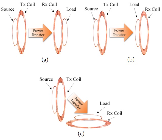
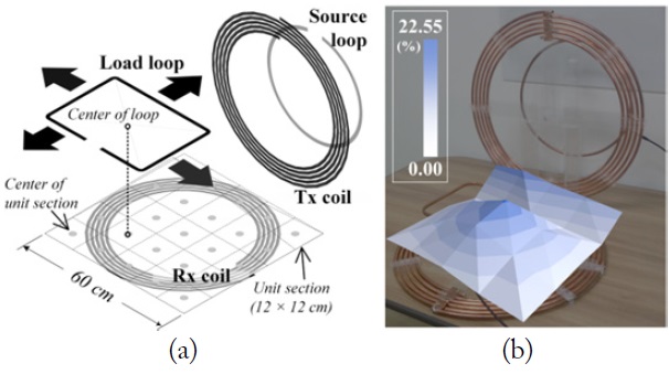
The concept of the proposed structure is “easy application in many places”. Fig. 1(a) shows the L-shape MR-WPT. The typical MR-WPT consists of four resonators. The order of arrangement of the resonators in MR-WPT does not experimentally affect the TE [4,5]. Therefore, the order of the arrangement of the load loop could be varied without TE changes in typical MR-WPT systems for practical applications. However, the rearranged Out-In MR-WPT shown in Fig. 1(b) has a spatial limitation for the Tx and Rx coils [5]. Electronic devices including a load loop must be placed between the Tx and Rx coils. Therefore, the system shown in Fig. 1(c) is proposed to this solve problem of the spatial limitation and to apply this system to L-shaped corners of the wall or at desks in an indoor environment. The proposed structure is basically modified from the Out-In MR-WPT as follows [5]: source loop - Tx coil - Load loop - Rx coil. In real applications, the large sized Tx part (Tx coil and source loop) and the Rx coil of the Rx part can be located in the wall and the desk, respectively, while the load loop of the Rx part is embedded in the stationary or mobile devices.
In measurement of the TE, three kinds of load loops according to the shape (circle and rectangle) and thickness (0.5 cm for wire and 1.0 cm for pipe) of the load loop for the performance comparison in practical laptop applications are tested. The TE is measured according to the TD, and it is also measured according to the misaligned location of the load loop on the Rx coil. In addition, for comparison of the practical performance according to the states of a laptop computer, we measured the TE in the active/non-active states and monitor-opened/closed states of the laptop computer. It is noted that the active/non active states of the laptop computer mean power on/off.
Section II describes the design and the fabrication of the proposed system. Thorough experiments and in-depth analysis are conducted, for comparing TEs in various use cases as described in Section III. The conclusion of this work is made in Section IV.
II. DESIGN AND CONFIGURATION OF THE L-SHAPE MR-WPT
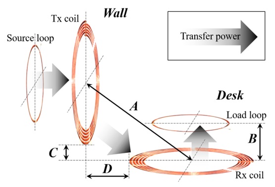
The proposed L-shape MR-WPT is modified from the Out- In MR-WPT [5]. Cross-coupling value between Tx coil and load loop was neglected for simplicity because the value is low [6]. Fig. 2 shows the structure and configuration of the proposed system. Distance A is TD, which is defined as the distance from centers of the Tx and Rx coils. Distance B is the height of the load loop from the Rx coil. Distance A is adjusted by two parameters. One is the height of the Tx part from the Rx coil, i.e., distance C, while the other is the distance between the Tx part and the Rx coil, i.e., distance D.
The source loop is excited by input power of 0 dBm. A magnetic field is generated around the source loop. Then, there is mutual inductance between the source loop and the Tx coil. Similarly, there is mutual inductance between the Tx and Rx coil as well. Finally, the power is transferred to the load loop by the mutual inductance between the Rx coil and the load loop.
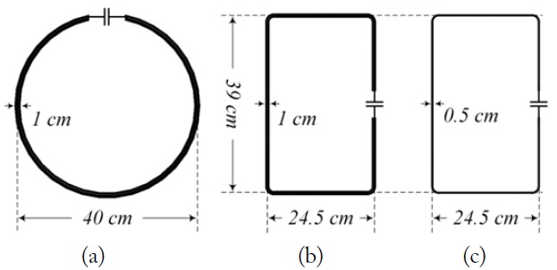
The Rx coil and the load loop in the Rx part are vertical to the Tx part and parallel to the floor in the L-shape MR-WPT. The resonators, loops, and coils are fabricated using 1.0-cmthick copper pipe. The source loop is a circular structure with a 40 cm diameter. The Tx and Rx coils are designed with the same-sized spiral coils. The outer circle is 60 cm, and the pipe is wound for 5 turns with a 1.5-cm pitch. A 6-pF capacitor is connected at the ends of coils to resonate at the operating frequency.
As shown in Fig. 3, there are three load loops with dimension combinations of two thicknesses and two shapes in the L-shape MR-WPT. One load loop, which is the control group, is a circular loop (CL) made with 1.0-cm-thick pipe. The CL is designed as a full-size replica of the source loop. The Tx and Rx parts in MR-WPT with the CL are symmetrical configurations. The other two load loops are fabricated from 1.0-cm-thick copper pipe and 0.5-cm-thick copper wire, and are designed using the same sized rectangular loops as those of a laptop computer, i.e., 24.5 cm × 39 cm. These load loops are referred to as rectangular pipe loop (RPL) and rectangular wire loop (RWL). The total length of the rectangular and circular loops is about 127 cm. With these two different shapes, we can determine the effect of the shape of the resonator on the magnetic coupling with the nearest one. Table 1 shows the simulated
[Table 1.] Simulated RLC values and Q-factor of coils and loops used in L-shape MR-WPT
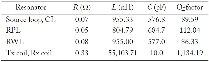
Simulated RLC values and Q-factor of coils and loops used in L-shape MR-WPT
[Table 2.] Capacitance values of coils and loops used in L-shape MR-WPT
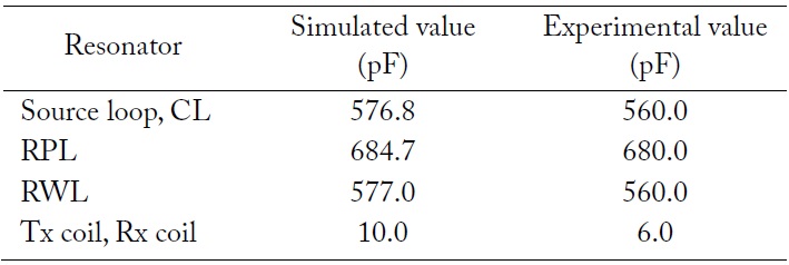
Capacitance values of coils and loops used in L-shape MR-WPT
III. RESULTS OF MEASUREMENTS AND SIMULATION
1. Measurement and Simulation of the L-shape MR-WPT
In the measurements, we compared the TE of the L-shape MR-WPT with that of the Out-In MR-WPT at the same TD, i.e., distance A [5]. The effects of the thickness and shape of the load loop on the TE of the MR-WPT are investigated. The trends of the TE of the L-shape MR-WPT with three load loops with respect to the TD are analyzed using the simulation and measurement results. We also investigated the trends of the TE of the L-shape MR-WPT when the load loop is misaligned from the center position at the optimized height. In addition, we verified the TE change in the monitor opened/closed states and active/non-active states of a laptop computer.
In these experiments, the source loop, Tx coil, and Rx coil described in Section II were fixed resonators in the fabricated MR-WPT. There are two variables in the measurement of transmission of the scattering parameter (
The measurement was conducted at distance
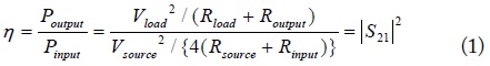
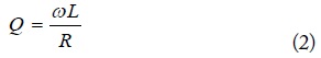
The TE were calculated using the resistance (
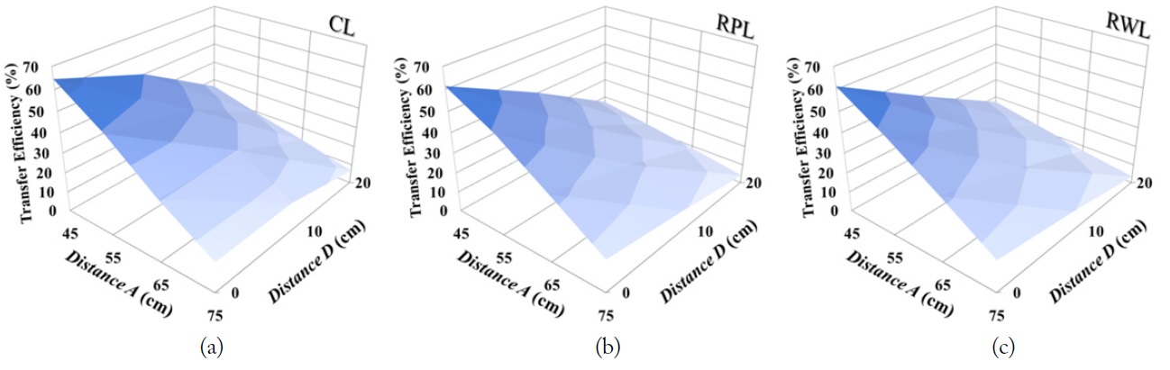
As shown in Table 3, the highest TE of the system with the CL was 64.48% at distance A of 45 cm and distance B of 0 cm. In the case of the system with the RPL, the highest TE was 61.43%, as shown in Table 3. There was about a 3.05% difference between the system with the CL and the RPL in terms of the TE. In the case of the RWL, the TE was 61.39%, as shown in Table 3. The two TEs between the system with the RWL and the RPL were almost the same. The average resonant frequency was about 6.96 ± 0.002 MHz. The trend of TE at dis tance
[Table 3.] Measurement results of TE of L-shape MR-WPT according to load loops (distance C = 0 cm)
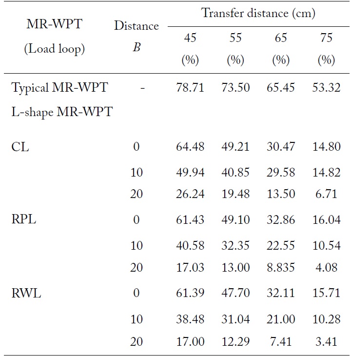
Measurement results of TE of L-shape MR-WPT according to load loops (distance C = 0 cm)
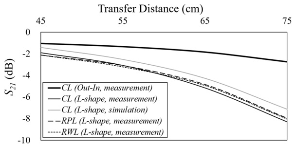
Quantitative comparisons of the TEs are carried out for the Out-In MR-WPT and the L-shape MR-WPT, as shown in Fig. 4. The two configurations are identical except for a right angle of the two parts. When the
The TEs of the systems with three kinds of the load loops are plotted in Fig. 5. The system with the CL operates best at the TDs of 45 to 55 cm. There was a slight difference among the three cases. It should be noted that the shape and the dimension of the load loop do not affect the TE dominantly.
The resistance of the bent part of the rectangular loop is relatively higher than any other parts [10]. This affects the Q-factor of
2. Measurement and Simulation of the Practical Applications
During use, the laptop computer could be laid on a misaligned location from the center on the Rx coil. This can cause a decrease in the TE. Depending on the misaligned distance of the load loop on the Rx coil, the magnitude of magnetic coupling in the L-shape MR-WPT can be changed. Note that for the wireless charging product, the optimal locations for the load loop and the Rx coil should be designed such that the TE is the highest. To verify the TE for various locations that a stationarytype electronic device can be laid, the horizontal position on the plane of the Rx coil was divided into 25 square unit sections, as shown in Fig. 6(a). When the center of the
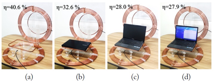
In addition, there are typically two electrical grounds, namely the display panel in the monitor frame and the circuit board in main frame. The conductive ground planes affect the magnetic field and coupling coefficient according to the position of laptop computer. To verify the effect of the conductive ground plane on the TE, a laptop-sized RPL was attached to the bottom of the laptop. As shown in Fig. 9, distance C was 0 cm, and the laptop computer with the load loop was placed over 10 cm from the Rx coil. These experiments showed that electronics such as the display panel and electronic circuit board, prevent the magnetic coupling. The laptop computer with the conductive ground plane affects the magnetic coupling in the proposed system. When the laptop computer was opened, the TE decreased from 32.6% to 28.0%. In contrast, in the active/nonactive state of the laptop, there is not much effect on the magnetic coupling of the L-shape MR-WPT. This result shows that the conductive ground plane has a greater impact on the electromagnetic performance than the active/non-active states.
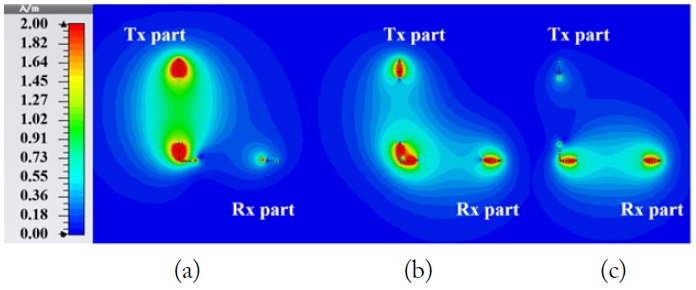
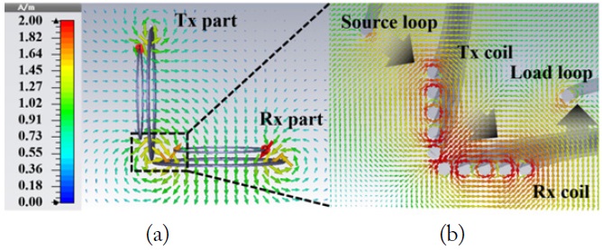
In this paper, we analyzed the proposed MR-WPT system with L-shape configurations for applications to the stationary or mobile devices. The electromagnetic field distributions and TEs of the proposed L-shape MR-WPT were simulated and measured. Results show that the TE of the L-shape MR-WPT is 64.48%, which is at least 13.93% lower than that of the