This article proposes a design of chipless RFID tag with dipole array structure that is fully printable using conductive ink. The proposed tags encode data based on spectral signature modulations. The reading range is considerably increased (2 m) while maintaining low transmission power (1 mW). Several prototype chipless RFID tags were fabricated and measured in the SHF and UHF bands. The proposed dipole array structure enhances the antenna gain of the passive tags and contributes to overcoming the low conductivity of conductive ink. In order to verify the utility of our proposal, the tags are manufactured on paper, using conductive ink, for the purpose of economic mass production.
Since Cardullo and Parks [1] introduced RFID supporting passive radio transponders with memory in the early 1970s, a number of research studies have been conducted. The RFID system without an IC chip, so-called chipless RFID, is suggested as a substitute for the barcode system. Chipless RFID tags are classified into three types depending on the modulation mechanisms, such as time, frequency, or phase [2]. Among the three types, RFID tags using spectral signature modulation is considered to be a good candidate for the upcoming market due to its encoding capacity. Early versions of spectral signatures were realized on microstrip substrate using copper.
Jalaly and Robertson [3] introduced the RF barcode using multiple dipole antennas. Each element resonates at different frequencies depending on their width and gap capacitance. Multi-resonator based chipless RFID tags, which support up to 35 bits of encoding capacity, were presented [4,5]. They used multi-resonating circuits with 35 spiral resonators and two cross-polarized antennas. However, most previous models have not achieved the goal of chipless RFID tags because of their bulky size and high cost.
In recent years, rapid advancements in materials have led RFID tags to be printed on paper using conductive ink [6-10]. This type of fabrication has remarkably lowered the cost and size of RFID tags, but the low conductivity issue remains as a drawback. Preradovic and Menicanin [11] presented a fully printable 3D stacked chipless RFID tag. Multiple dipole elements were printed on 5 μm polyimide film with conductive ink. The cross-polarization expanded the data capacity to 8 bits. However, the reading range was relatively short (less than 20 cm) due to low conductivity.
In this paper, we present novel, fully printable chipless RFID tags based on dipole array structures. The tags encode data by using spectral signature modulation. The reading range of the proposed dipole array structure is greatly enhanced by the tags’ increased antenna gain. The tags are screen-printed onto plain paper using conductive ink. In addition, it will be shown that tags can be designed at any desired frequency within the UHF and SHF bands. The effect of the proposed chipless RFID tags is also discussed in terms of RFID tag types, number of elements, reading ranges, and so on.
II. DESIGN OF CHIPLESS RFID TAGS
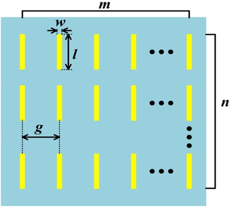
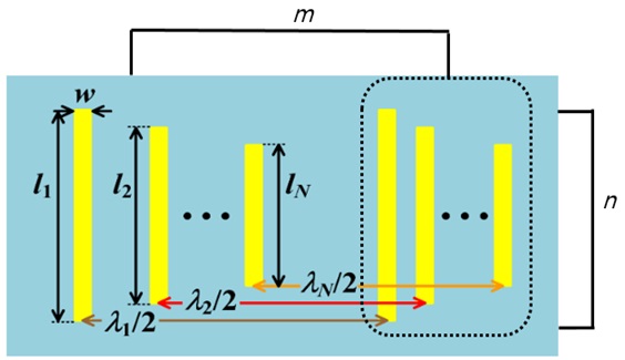
Two different types of chipless RFID tags are depicted in Figs. 1 and 2, respectively, and are differentiated according to the number of operating frequencies they support.
The geometry shown in Fig. 1 supports a single frequency. The tag is composed of a number of identical elements. The length of the dipole antenna,
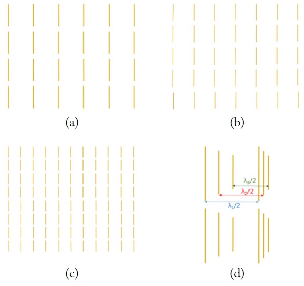
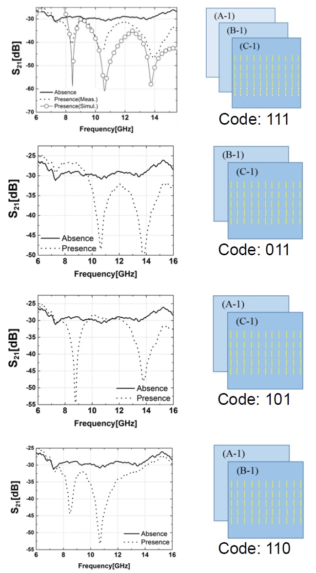
The operating principle of the proposed RFID tags is simply based on presence and absence states [11]. When tags are located between two reader antennas, they contribute to a strong stopband. Encoding 0 or 1 can be easily determined by distinguishing their presence or absence. Fig. 3 shows several types of the fabricated RFID tags: Fig. 3(a)-(c) show the RFID tags supporting single frequency. Fig. 3(d) shows the multi-frequency RF tag operating between 2.5 and 4 GHz, which supports 3 bits of encoding capacity. The specific dimensions of the tags are given in Table 1.
[Table 1.] Dimensions of fabricated chipless RFID tags
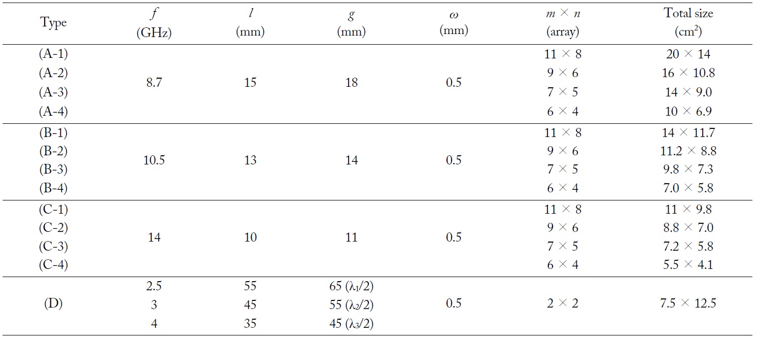
Dimensions of fabricated chipless RFID tags
III. PRINTING CHIPLESS RFID TAGS ON PAPER
For the fabrication, we chose Silveray-RM conductive ink, which is formulated for printed electronics applications, such as RFID and membrane switches. The ink contains 55%-66% silver paste that provides 5-10 μm of thickness. The curable temperature is 150℃ and the time is less than 30 minutes. The average resistance of the ink is 23.01 mΩ/□. Its conductivity is approximately 6%-7% compared to that of copper. The thickness of a single sheet for a fabricated RFID tag on paper is about 110 μm.
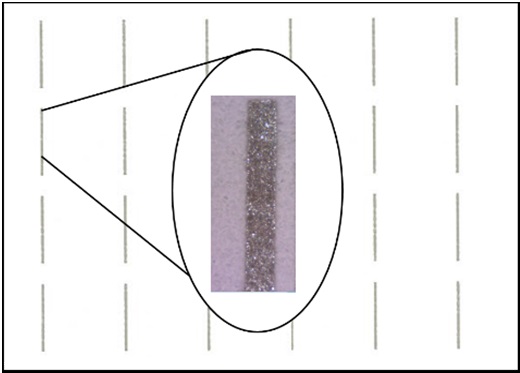
A partial microscopic view of the fabricated RFID tag is shown in Fig. 4. It is obvious that the conductivity of printed lines is lower than that of a metal-based medium, since the small particles of conductive ink are not homogeneous. Therefore, the proposed array structure can be more advantageous for overcoming the innate limitation of conductive ink.
Paper has a number of advantages as a substrate. Firstly, it is cost-effective and therefore well suited to mass production. Secondly, it supports inkjet-, screen-, and reel-to-reel printing techniques. We chose the screen-printing method to demonstrate that it is a good candidate for mass production. Moreover, unlike chemical substrates such as FR-4 and PET films, paper is an environmentally benign material: it is not harmful, and it decomposes easily. However, the electrical characteristics of paper should be considered before designing RFID tags on it. Previous studies [14-16] have already shown that paper has appropriate electrical properties as a substrate for UHF and SHF frequency bands.
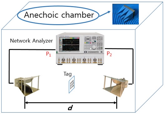
Various measurements were made to validate the proposed chipless RFID system. Fig. 5 illustrates the measurement setup. Two vertically polarized horn antennas are placed bi-statically at a distance of
Fig. 6 shows simulated and measured
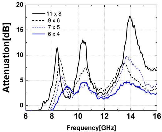
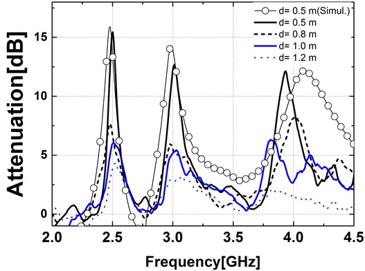
Fig. 7 shows the attenuation in dB scale with respect to the number of dipole elements used in the array structure. The distance
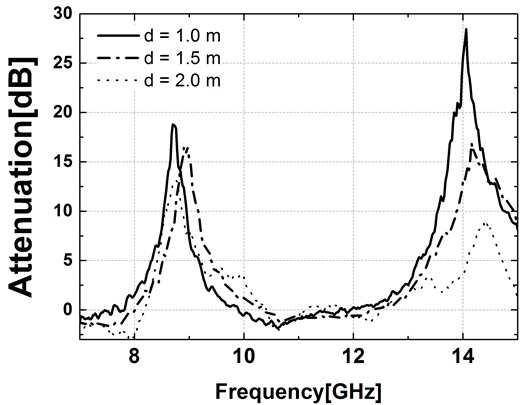
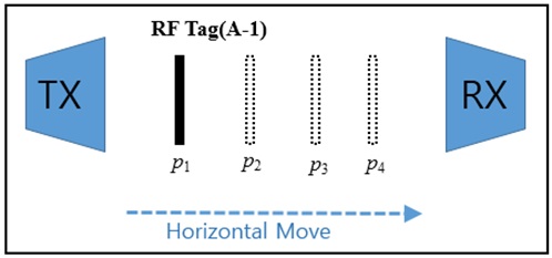
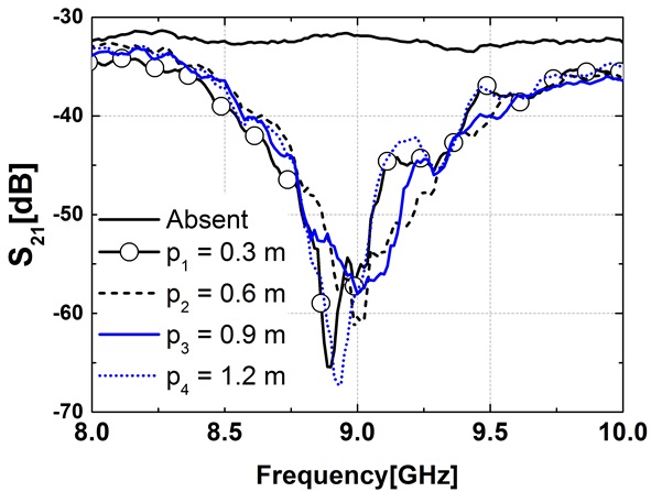
Fig. 10 shows the measurement setup with respect to the different positions of the RFID tags. The distance,
This study presented a fully printable chipless RFID system with a dipole array structure. We enhanced the reading range up to 2 m, which is 5 to 10 times further than earlier studies [9,11]. The tags were printed on eco-friendly paper using conductive ink. The dipole array structure played an important role in increasing the gain of the passive tags, and compensated for the low conductivity of the conductive ink while maintaining the low transmission power of 0 dBm. It was shown that various combinations of multi-layer tags can provide up to 6 bits of information. Additionally, we verified that the tags can be designed at any desired frequency within the UHF and SHF bands. In conclusion, the proposed chipless RFID system, with its low cost, eco-friendly application, and longer reading range, showed great potential to replace current RFID systems.