We present a new design approach and an example design for an image-space telecentric two-mirror system that has a fast f-number and a wide-field line image. The initial design of the telecentric mirror system is a conventional axially symmetric system, consisting of a flat primary mirror with fourth-order aspheric deformation and an oblate ellipsoidal secondary mirror to correct spherical aberration, coma, and field curvature. Even though in the optimized design the primary mirror is tilted, to avoid ray obstruction by the secondary mirror, the image-space telecentric two-mirror system shows quite good imaging performance, for a line imager.
The most useful characteristic of a mirror system is that the system does not have any chromatic variation. In the conventional axially symmetric configuration, a mirror system has a central obstruction and field-of-view restriction due to the vignetting effect. Hence, such a mirror system is mostly used for narrow-field objectives, such as astronomical telescopes and satellite cameras. Off-axial construction of a mirror system, however, can overcome the intrinsic problems of the conventional configuration, and could be used for wide-field applications [1].
In this study we present a new design approach for an image-space telecentric two-mirror system, corrected for spherical aberration, coma, and field curvature. We are interested in the two-mirror system as a possible candidate for a line-imaging objective of a hyperspectral imaging system [2]. Since an object-space telecentric spectrometer is used for the hyperspectral imaging system, image-space telecentricity is necessary for the two-mirror system.
Various two-mirror systems with corrected third-order aberrations have been known for a long time [3-6]. Because of image-space telecentricity, the conventional design approach for a two-mirror system can give an aplanatic design only, but is insufficient for designing a wide-field objective. From the analytic expressions of residual aberrations of the aplanatic design, we found that the primary mirror should be flat, to obtain a flat-field aplanatic design satisfying image-space telecentricity, but the conic constant of the primary mirror cannot be used to correct third-order aberrations in that case. We overcome this problem using the fourth-order aspheric deformation instead of the conic constant.
II. APLANATIC TWO-MIRROR SYSTEM
A conic surface with axial symmetry about the optical axis (
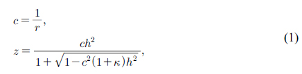
where
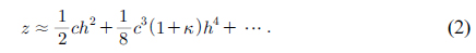
In modern optical design, the general aspheric surface is widely used to correct optical aberrations. Let us define a general aspheric surface that has fourth-order deformation on the sphere as follows:
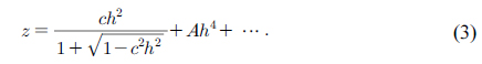
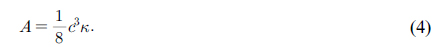
In this case, the fourth-order deformation
For a flat surface (
A two-mirror system has five design parameters: two curvature radii (
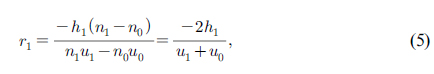

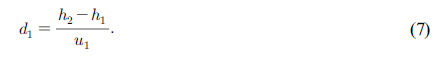
In Fig. 1, let us define the ratio of incident heights of the marginal ray as
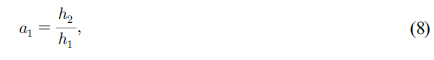
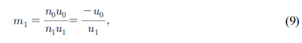
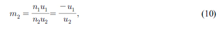
Then the curvature radii and axial distance can be expressed as
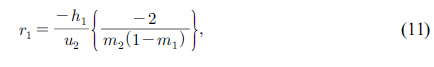
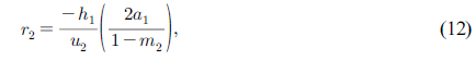
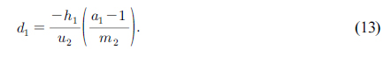
In Eqs. (11)-(13), (
The third-order aberrations of a two-mirror system can be categorized by two parts: The main ones are the contributions of spherical surfaces, and the orders are the contributions of aspheric deformations. If the primary mirror is the aperture stop of the two-mirror system, then the spherical aberration
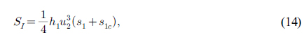
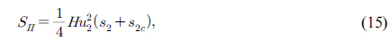

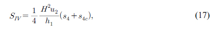
In Eqs. (14)-(17),
Practically, we are interested in field curvature rather than Petzval field curvature. The third-order term of field curvature

In Eqs. (14) and (15),
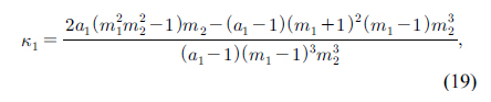
The aplanatic design of a two-mirror system based on Eqs. (19) and (20) is the well known Ritchey-Chrétien (R-C) system [3]. The residual astigmatism
If we take a suitable combination of (
III. ABERRATION CORRECTION OF A TELECENTRIC SYSTEM
3.1. Stop Position and Telecentric Condition
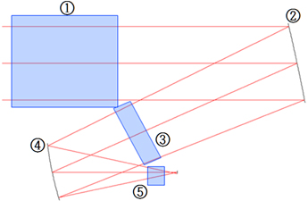
In this study, the two-mirror system we are designing requires image-space telecentricity. The aperture stop of a mirror system should be located where the stop does not interfere with incoming and outgoing beams. According to Fig. 2 there are five possible stop positions in a two-mirror system. To satisfy image-space telecentricity, the stop position should be the first focal point of the system, so positions ④ and ⑤ cannot be candidates. If we choose position ①, the sizes of the primary mirror M1 and secondary mirror M2 become large, which is undesirable. If we choose position ③, the tilting angles of M1 and M2 should be large enough to avoid ray obstructions by the stop. Hence, we choose position ②, the aperture stop at M1. In this case we do not need extra mechanical structure for the aperture stop, and the diameter of M1 can be minimized.
Since M1 is taken as the aperture stop, the vertex of M1 should be the first focal point of M2, to satisfy image-space telecentricity. The separation between mirrors
where
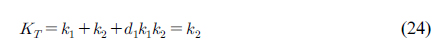
From Eq. (24), the power of refraction of M1,
which is the telecentric condition where the aperture stop is located at the primary mirror.
3.2. Aberration Correction for an Object at Infinity
If the object is located at infinity (
By applying the telecentric condition of Eq. (25) to Eq. (26), we obtain the residual astigmatism of the image-space telecentric system as
If the two-mirror system has a specified power, the magnification
Let us consider the residual field curvature. If
By applying the telecentric condition to Eq. (28), the residual field curvature of the telecentric system is given by
If the two-mirror system has a specified refracting power and M1 has refracting power, the magnification
Let us consider an image-space telecentric two-mirror system having a flat primary mirror. In this case the magnification
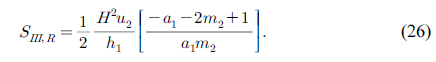
By applying the telecentric condition to Eq. (30), the residual astigmatism of the telecentric system is given by
This means that the residual astigmatism cannot be corrected.
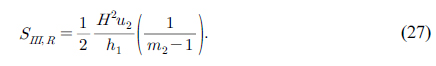
Let us now consider the residual field curvature. Applying the telecentric condition to Eq. (22), the residual field curvature of the telecentric system is given by
If

If the object is located at infinity and the primary mirror is flat (
As discussed, we can correct the residual field curvature of an image-space telecentric system by taking
Let us define the primary mirror M1 using Eq. (3), a general aspheric with fourth-order term
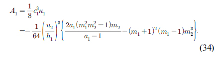
By applying the telecentric condition to Eq. (34) and setting
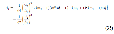
Let us also consider
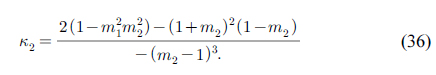
For the case of

M2 is an oblate ellipsoid. Using Eqs. (35) and (37), we can get an image-space telecentric two-mirror system corrected for spherical aberration, coma, and field curvature.
IV. OPTICAL DESIGN AND ABERRATION ANALYSIS
In the previous section, a two-mirror system having a flat M1 with fourth-order aspheric deformation, and an oblate ellipsoidal M2, can be corrected for three kinds of third-order aberration: spherical aberration, coma, and field curvature. Table 1(a) is an example design of an image-space telecentric two-mirror system with an axially symmetric configuration. Let us call this the initial design. Since M2 blocks all of the beams incident upon M1, the initial design is just a sample to show the results of the previous discussion. The initial design is a fast and wide-field mirror system with effective focal length of 100 mm,
[TABLE 1.] Initial design of the telecentric two-mirror system (axially symmetric configuration)
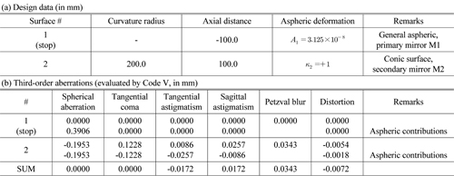
Initial design of the telecentric two-mirror system (axially symmetric configuration)
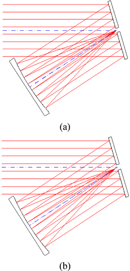
Figure 4 shows the optical layouts of the decentered design (a) and the optimized design (b). The decentered design is an off-axial modification of the initial design, to avoid ray obstruction. M1 of the decentered design has a tilt angle of 16.5°. The line image along the horizontal direction (
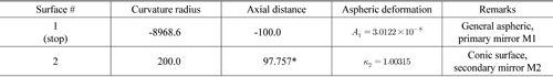
Optimized design of the telecentric two-mirror system (decentered and optimized for line image along the x-axis, in mm)
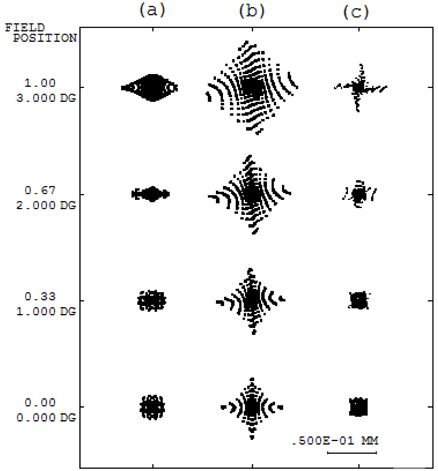
Spot sizes for the initial design (a), the decentered design (b), and the optimized design (c) are listed in Table 3. Figure 5 shows spot diagrams for the three designs. The residual wavefront aberrations of the three designs are listed in Table 4. The bold entries in Table 4 indicate the dominant residual aberrations. The spot diagrams shown in Fig. 5(a) and Zernike coefficients listed in Table 4(a) show that the primary astigmatism (Z4) is the dominant aberration of the initial design. From Fig. 5(b) and Table 3(b), quite large astigmatisms (Z4, Z6, and Z12) were introduced in the decentered system because of M1’s tilt. With optimization, the imaging performance of the optimized design improved, but the residual astigmatisms are the limiting factors. If we were to use anamorphic surfaces, then the residual aberrations might be corrected, but we use only axially symmetric surfaces, for easy fabrication and assembly.
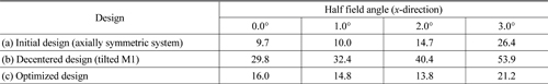
RMS spot size of the initial design, the decentered design, and the optimized design, for the best focus (in μm)
[TABLE 4.] Dominant wavefront aberrations of the two-mirror designs (in units of λ @ 632.8 nm)
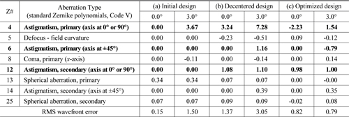
Dominant wavefront aberrations of the two-mirror designs (in units of λ @ 632.8 nm)
In this paper, we present a new design approach and example design for a two-mirror system with the aperture stop lying on the primary mirror M1, and which satisfies image-space telecentricity. From the analytic expressions for residual aberrations of the Ritchey-Chrétien system, we show that the residual astigmatism cannot be corrected if the object is at infinity, but the residual field curvature can be corrected by using a flat primary mirror M1. Since the conic constant cannot be defined for a flat M1, for correction we use the fourth-order aspheric deformation
As an example, an optimized design for a two-mirror system that satisfies image-space telecentricity is presented. Since the initial design corrected for spherical aberration, coma, and field curvature has an axially symmetric configuration, the rays incident to the primary mirror M1 are obscured by the secondary mirror. Hence a tilted M1 is used for redesigning the two-mirror system to avoid ray obscuration. The optimized system is designed for a fast and wide-field line imaging objective of