In this study, an ultraviolet Raman spectrometer was designed and fabricated to detect chemical contamination on the ground. The region of the Raman spectrum that indicated the characteristics of the chemicals was 350-3800 cm-1. To fabricate a Raman spectrometer operating in this range, the layout and angle of optical components of the spectrometer were designed using a grating equation. Experimental devices were configured to measure the Raman spectra of chemicals based on the fabricated Raman spectrometer. The wavenumber of the spectrometer was calibrated by measuring the Raman spectrum of polytetra-fluoroethylene, O2, and N2. The spectral range of the spectrometer was measured to be 23.46 nm (3442 cm-1) with a resolution of 0.195 nm (30.3 cm-1) at 253.65 nm. After calibration, the main Raman peaks of cyclohexane, methanol, and acetonitrile were found to be similar to the references within a relative error of 0.55%.
As industries and technologies have undergone development, the usage of various chemical substances has also increased. Some of these substances can adversely affect human health. If such substances are released to atmospheric environments or to the ground in large quantities, they can be fatal. Consequently, it is necessary to develop equipment that can accurately and rapidly detect chemical contaminants so as to respond proactively to prevent or at least minimize damage. There are various methods for detecting chemical substances, such as Raman spectroscopy, ion mobility spectroscopy, flame photometry, surface acoustic wave sensor, colorimetric detection, photo ionization detection, and mass spectrometry. Among these methods, Raman spectroscopy can detect chemicals in all forms (gases, liquid, solid, and aerosol) non-destructively [1]. It has the advantage of safe equipment operation with a non-contact and indirect sampling method.
Two typical Raman spectrometers are dispersion spectrometers using a grating and interference spectrometers using an interferometer [2, 3]. Dispersion spectrometers can measure the spectrum in real time by detecting light using a charge-coupled device (CCD) or a photodiode array. Recently, ultraviolet (UV) light source technology has undergone advancements and the development of Raman spectrometers based on UV lasers has become active [4, 5]. In particular, if a light source with 250 nm or shorter wavelength is used, fluorescence can be avoided in a Raman spectrum measurement and the measurement can be performed in the field regardless of time of day because of the longer wavelength of solar light [6]. However, the shorter the wavelength, the narrower the gap between Raman peaks that indicates the characteristics of chemicals; thus, a high resolution Raman spectrometer is needed.
In this study, a UV Raman spectrometer for Raman spectrum measurement of chemicals was designed and tested. The UV Raman spectrometer satisfying spectral region and resolution requirements was designed using a grating equation at a wavelength of 248.35 nm, which is the wavelength of a KrF excimer laser. Then, the spectrometer was fabricated and calibrated using well-known samples. The spectral region and resolution of the spectrometer were measured and compared with the design values. Finally, Raman spectra of chemicals were measured and compared with those in the reference [15] to verify the spectrometer as a UV Raman spectrometer for chemical detection.
2.1. Design and Fabrication of the Spectrometer
For the design of a spectrometer, spectral range and resolution should be determined. The spectral range and resolution of a spectrometer for Raman spectroscopy is determined by the wavelength of the laser used as the induced light source. The Raman characteristics of chemicals are in the range of 350-3800 cm-1[7]. If a KrF excimer laser at 248.35 nm is used as the induced light source, the wavelength range corresponding to the Raman spectral range is 23.7 nm. A resolution of 30 cm-1 in wavenumber is required to resolve the characteristics of chemicals, corresponding to a resolution of 0.21 nm in wavelength with a KrF laser. The slit width is an important factor that determines the light intensity and resolution of a spectrometer. The wider the slit is, the more intense light can be obtained but the worse the resolution of the spectrometer. To achieve a higher resolution with a wider slit, the focal length of the mirror becomes longer, yielding a larger spectrometer. Thus, the design parameters of the spectrometer such as slit width and focal length should be determined by considering the purpose of the spectrometer. In general, collimating and focusing mirrors have the same focal length in a spectrometer. The longer the focal lengths of the two mirrors, the higher the resolution; however, the equipment becomes larger. A small spectrometer with high resolution can be designed with a high-density grating. Additionally, the Raman signal can be amplified if an intensifier CCD (ICCD) or electron multiplying CCD (EMCCD) is utilized to improve the signal-to-noise (SNR) ratio [8].
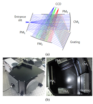
In this study, a spectrometer was designed and fabricated using a high-density grating of 3600 lines/mm and an ICCD for amplifying signals. A circle-to-line fibre bundle was installed at the entrance slit of the spectrometer and it can be applied to a variety of equipment. This kind of fibre bundle allows increasing optical throughput. The design parameters are shown in Table 1. The diffraction angle of the incident light at various wavelengths and incident angles at the grating can be estimated using a grating equation. The diffraction angle of the first-order incident light at a wavelength of 250.5 nm and an incident angle of 11.5° is given by 44.7°. To achieve a spectral range of 23.7 nm with an angle dispersion of 5.06 pm-1, the focal length of the mirrors should be larger than or equal to 208 mm. Based on the calculated results, a spectrometer with a focal length of 208 mm was designed using a diffraction grating of 3600 lines/mm. Because the diffraction angle at the grating was 44.7°, the size of the spectrometer could be very large if it was designed using a typical Czerny-Turner type. Thus, the folded Czerny-Turner type was devised to reduce the size of the spectrometer using inlet and outlet mirrors with a hole in the centre to overlap the optical path [9, 10]. Figure 1(a) shows the structure and optical path of the spectrometer and Fig. 1(b) shows the images of the fabricated spectrometer.
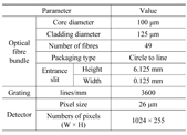
Design parameters
The designed spectrometer gives a spectral range of 23.7 nm and resolution of 0.12 nm, which is sufficient to analyse the Raman spectra of chemicals.
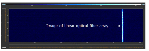
Light from a mercury lamp was injected to the spectrometer using the fibre bundle to confirm that the image is formed well on the CCD. Figure 2 shows the linear end of the optical fibre bundle formed on the CCD, indicating that the spectrometer was well aligned.
2.2. Raman Spectrum Measurement System
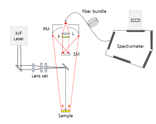
Figure 3 shows the schematic diagram of the (standoff) Raman system for measuring chemicals. A KrF excimer laser was used as the light source to generate Raman scattering of the chemicals. The pulse width of the laser was 10 ns at a repetition rate of 10 Hz. The laser with an energy of 4.5 mJ was irradiated on the chemicals. A Gregorian telescope with a primary mirror diameter of 6 inches was employed to collect the Raman scattered light. The optic axes of the telescope and irradiated laser were coaxially positioned as shown in Fig. 3. A single spherical lens and two cylindrical lenses were used to produce a beam size of 3 × 6 mm on the sample.
After irradiation of the laser, the scattered light from the sample is converged to the secondary mirror by the primary mirror of the telescope in a brightly lit room. The light is collimated by the secondary mirror and passes the Raman filter (LP02-248RS, Semrock) with the cut-off wavelength of 251.1 nm to remove Rayleigh scattered light from the collected light. Finally, the light is focused on the inlet of the optical fibre bundle by an aspherical lens and transferred to the spectrometer.
The circle-to-line optical fibre bundle consisted of 49 fibres with a cladding diameter of 125 μm and core diameter of 100 μm. The attenuation of each optical fibre is 0.457 dB/m at 250 nm. Because some of the circular-shaped light collected by the telescope can be blocked by the slit in the spectrometer, the shape of the light was converted to linear shape using the fibre bundle and hence the optical throughput could be enhanced.
3.1. Wavenumber Calibration and Performance of the Spectrometer
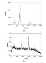
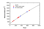
In general, the wavenumber of the spectrometer is calibrated using well-known transition lines of mercury. Because the transition lines in the spectral range of the spectrometer are close, the spectrometer was calibrated using the Raman spectra of polytetrafluoroethylene (PTFE), oxygen, and nitrogen acquired by the system [11-14]. The KrF laser was irradiated on the PTFE sample with a diameter of 25.4 mm and thickness of 5 mm. Raman scattered light of PTFE was focused on the optical fibre bundle by the telescope and transferred to the spectrometer by the optical fibre bundle. The Raman scattered light of PTFE was separated according to wavelength at the spectrograph and then imaged on the CCD. By full vertical binning of the CCD image, the Raman spectrum of PTFE was obtained. To acquire Raman signals of O2 and N2 in the atmosphere, absorption paper with small Raman scattering and fluorescence was placed at the sample position, and then Raman spectra of O2 and N2 were acquired using the same method for the PTFE Raman spectrum measurement. Figure 4 shows the Raman spectra of PTFE, O2, and N2. The Raman peaks are evenly distributed over the spectral range and they are appropriate for wavenumber calibration. The SNR of the O2 and N2 Raman spectra worse than that of the PTFE Raman spectra originated from the fact that the densities of the O2 and N2 gases are lower than that of the solid PTFE; thus the intensity of the Raman scattered light generated per unit area was tens to hundreds of times smaller for the gases. Figure 5 shows the calibration result estimated using second-order fitting of the Raman peaks compared with the CCD pixel position and wavenumber.
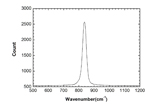
The spectral range verified by the wavenumber calibration was 23.46 nm (3442 cm-1). The resolution was 0.195 nm (30 cm-1) by measuring the full width at half maximum of the spectrum of a mercury lamp, which is larger than the designed value. Figure 6 shows a transition line of the mercury lamp. The errors compared with the designed value could originate from diffraction and aberration at each of the optical components in the spectrometer. The error mainly came from the optical fibre bundle used as the inlet slit of the spectrometer because light can be transmitted through not only the core but also the cladding. The optical path of the light transmitted through the cladding cannot be estimated and the light can act as stray light. In addition, the width of the actual slit can be widened because of the packaging tolerance at the linear end of the optical fibre bundle.
If the packaging tolerance is 100 μm, the resolution would increase by more than twice the designed value. Thus, a resolution closer to the designed value can be obtained by installing an additional slit at the inlet of the spectrometer.
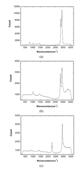
3.2. Raman Spectra of Chemicals
The Raman spectra were acquired by irradiating the KrF laser onto cyclohexane, methanol, and acetonitrile at the sample position (Fig. 7). The spectra of the chemicals were compared with the reference values listed in Table 2 [15]. The relative errors between the reference and measurement values were within 0.55%. The result shows that the fabricated Raman spectrometer works properly for measuring the Raman spectra of the chemicals.
[TABLE 2.] Main Raman peaks of the chemicals
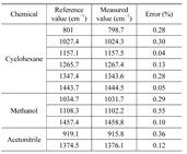
Main Raman peaks of the chemicals
In this paper, the design of a UV Raman spectrometer with high resolution that can analyse chemicals was described. To achieve high resolution and small size of the spectrometer, the diffraction angle was increased by using a high-density grating and the folded Czerny-Turner structure was applied. Based on the designed result, a Raman spectrometer was fabricated. To verify the performance of the spectrometer, a Raman system was configured. The Raman spectra of PTFE and atmospheric O2 and N2 were measured to calibrate the wavenumber of the Raman spectrometer, and then the spectral range and resolution were measured. The spectral range and resolution were 23.46 nm (3442 cm-1) and 0.195 nm (30 cm-1) at 253.65 nm, respectively, and they were similar to the designed value. The Raman spectra of cyclohexane, methanol, and acetonitrile were measured and compared with the reference values. The relative errors between the measured and reference values were within 0.55% or smaller, showing that the measured spectra were well matched to the reference spectra. It should be noted that the fabricated Raman spectrometer is well suited for UV Raman spectroscopy. We believe that the UV Raman spectrometer can be used to detect chemicals by combining with a robust and ruggedized Raman collecting system and developing efficient detection algorithms.