A diffraction limited optical system for head mounted displays (HMDs) was designed. This optical system consists of four modules, including 1:5 mm and 5:30 mm beam expanders, polarization grating-polarization conversion system (PG-PCS) and refractive/diffractive projection optical module. The PG-PCS module transforms the unpolarized Gaussian beam to a linearly polarized beam and it simultaneously homogenizes the spatial intensity profile. The optical projector module has a 30° field of view, a 22 mm eye relief, and a 10 mm exit pupil diameter with a compact structure. Common acrylic materials were utilized in the optical design process; therefore, the final optical system was lightweight. The whole optical system is suitable for a 0.7 inch liquid crystal on silicon microdisplay (LCOS) with HDTV resolution (1920×1080) and 8.0 μm pixel pitch.
HMDs have found applications in a variety of fields: scientific simulation, navigation, fire and remote control, ranger application, surgery, entertainment, and portable workstations [1]. Depending on their purpose, HMDs are divided into displays with military and civilian applications. In general, the different types of designs may be divided into four classifications; Pupil and non-pupil, refractive and cat dioptric, inside vision, and finally on-axial and off-axial [2-4]. In this article we focused on designing the pupil type (by which all emitted beams are transmitted through an aperture called the “exit pupil”). In this type the observer can view the display imagery (or symbology) as an overlay on the external scene. Placement of the system on the head of the observer imposes stringent requirements on the overall size and mass of the entire system. There are common challenging design issues: a long eye relief, a large exit pupil, compact and lightweight modules, and good optical performance. With pure refractive optics, the optical system cannot meet these requirements. Diffractive optics can reduce size and weight while providing some unique functions that would be difficult to implement with conventional refractive optics. Creating a high quality image is a common concern for optoelectronic designers. The image quality for this system is a function of light source, image source and optical design. Therefore, there are three fundamental challenges that must be responded to for a favorable design.
In this article, the optical design of the elements is carried out with “ZEMAX” and “LIGHTTRANS” programs based on constraints. Our designed system’s novelties are: diffraction limited optical designs, high efficiency diffractive optical elements (DOEs), with a compact structure and a light weight.
The HMD system is composed of three main parts; the light source, the image source and the optic modules. The light source is made of a green diode laser with a wave-length of 532nm; its output light intensity is controlled to create different levels of brightness. Inherent parallel beams of laser light placed in the light cone face the image source, thus creating minimal waste and desired thumbnail display clarity. The laser’s ability to couple with the selected microdisplay in higher efficiency than other light sources made it an ideal choice to use in our system. Various kinds of microdisplays have been developed at present; they are contributing to the development of HMD systems by making the whole structure simplified and by providing the precondition for better application of HMD [5]. The selected image source type is LCOS; it is a reflective microdisplay technology based on a silicon backplane. Using standard CMOS processes, microdisplays with extremely small pixels, high fill factor (pixel aperture ratio) and low fabrication costs can be realized. An LCOS has the advantages of high contrast ratio (>1000:1), high lifetime (>20,000 hours), high throughput and a wide dynamic control range.
III. OPTICAL DESIGN REQUIREMENTS
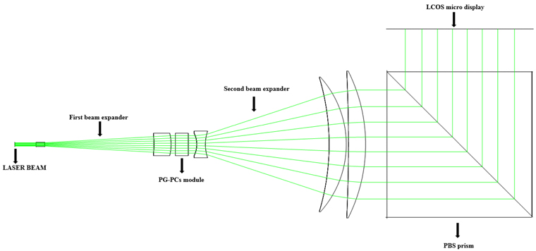
The light emitted from the laser diode source enters the first beam expander with 1.0 mm diameter and exits from it with a diameter of 5.0 mm, then this 5.0 mm unpolarized Gaussian beam enters the PG-PCS module and exits from it with the same diameter (the incident and outgoing beam is perpendicular to the plane of Fly Eye Lens (FEL)), and enters the second 5:30 mm beam expander, finally with the diameter of 30.0 mm it enters a polarized beam splitter cube (PBS) and is reflected on the LCOS surface perfectly illuminating it, then the modulated light is reflected again from the LCOS surface and enters a projector. An optical module is an important part of the HMD system, which causes direct effects on image quality, so design of the optical system is becoming significant. Although requirements of optical systems are different for different applications, generally, HMD functional requirements lead to one optical system with a long eye relief, a large exit pupil, and a wide field of view (FOV) [5]. Though the diameter of the pupil of the human eye is typically 3-5 mm, in order to allow for an eye swivel without causing vignetting, the exit pupil of the eyepiece system for HMD should be more than 10 mm. For getting an optimum FOV, the human’s eye pupil should be placed just on the exit pupil of the HMD, which requires the optical system to have a big enough eye relief. Generally the physical eye relief should be more than 20 mm [6].
IV. OPTICAL CONFIGURATION OF ADAPTING MODULE
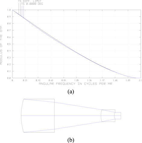
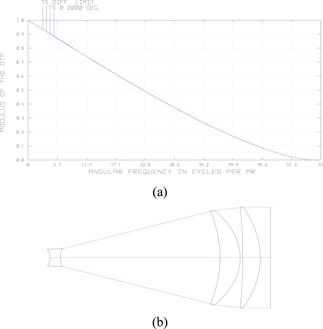
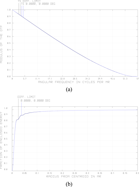
Although the laser light is very useful, its output light profile is Gaussian. Since making a uniform image in the whole field of view is a very important consideration, this problem should be eliminated as much as possible. It is possible to design an adapting light module; which is composed of three elements: two beam expanders and one PG-PCS. The beam expanders’ designs are diffraction limited, and no more aberrations are added to their output according to Figs. 1 and 2. Their lens data from ZEMAX are shown in Tables 1 and 2.
The first beam expander’s lens data from ZEMAX (unit: thickness/distance in mm, angle in degree)
The second beam expander’s lens data from ZEMAX (unit: thickness/distance in mm, angle in degree)
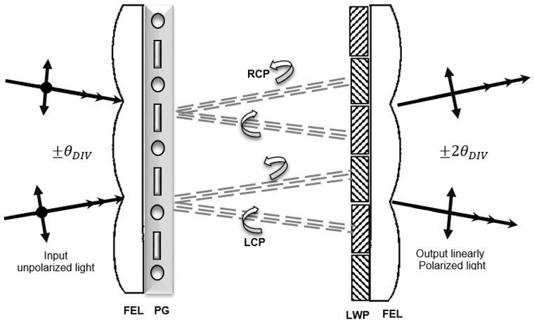
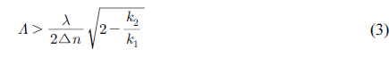
Since in this type of microdisplay polarized light is required, we must use a light modulator. The easiest solution is to use a polarizer, which provides the desired polarization but creates a lot of loss in light transmission (more than 50%). The best alternative is to use a PG-PCS, first introduced by Escuti et al. [7]. It performs two important tasks for achieving good image quality and optical efficiency: it transforms the circular cross-sectional area of the Gaussian beam to rectangular uniform intensity profile and it simultaneously provides the output linearly polarized light from input unpolarized light. Therefore, using this module many problems such as non-ideal throughput and brightness uniformity have been overcome. PG-PCS consists of three parts: FEL, polarization grating (PG), and a retarder element. FEL is a two-dimensional array of microlenses that functions via refraction. Unpolarized incident light is concentrated by the FEL and diffracted in the first order by the PG. These two beams are orthogonal circularly polarized and focused on the focal plane of the FEL. The retarder element is composed of two alternating retardation areas at the focal plane of the FEL. These areas are oriented with their optical axis at ±45° to provide ±90° retardation of phase shift of the light diffracted from the PG. Therefore, this retarder element creates the same linear polarization from two orthogonal circular polarizations (Fig. 3). The PG period
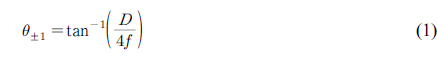
where
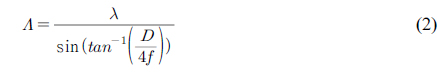
Approximately complete polarization conversion may occur when the input divergence angle is smaller than the diffraction angle ( ±
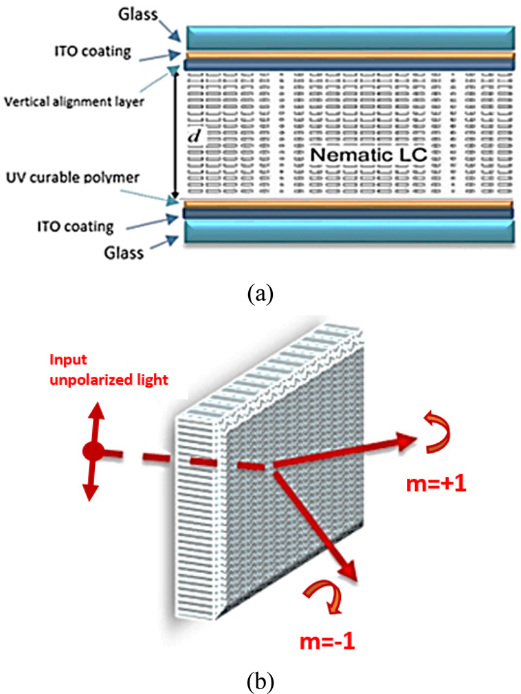
The conditions have been prepared for designing the optimized PG element with shorter period, greater diffraction angles, and high diffractive efficiency with more than 99.747% transmission percent for unpolarized light with wavelength 532 nm. As shown in Figs. 4(a) and (b), the PG element is built from various layers where the foremost elements include two glazed substrate beds placed at both ends of this cell and covered by indium tin oxide (ITO) coating. A polymeric layer is placed on the lower substrate on which diffractive element is located and a vertical alignment layer is placed to adjust the liquid crystal (LC) on the glazed substrate bed at the other end of this cell. The given cell is filled with LC by observance of requirements of production and two ends of ITO coated layers are connected to the power supply (with voltage proportional to properties of the liquid crystal), and thereby they are controlled by output voltage to orient LC molecules.
LIGHTTRANCE strong software has been utilized to design the PG [9]. For ease of production, we have executed our design based on a sinusoidal structure of 2-D form. We have selected Poly(methyl methacrylate) nanocomposite (PMMA) for substrate material. To achieve the optimized PG, we have used liquid crystal W1791 (composed of fluoro-substituted alkyltolane- and alkylphenyl tolane isothiocyanates) [10]. The optical properties of this compound are expressed in Table 3.
[Table 3.] Specification of liquid crystal mixture [10]
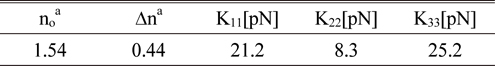
Specification of liquid crystal mixture [10]
The smallest permissible period of grating can be obtained from the below equation [11]:
Where,

Therefore, in terms of design and production constraints, we consider periodic length 0.8 μm and its modulation depth as 0.75 μm. We have used anti-reflection coating on electrode and intermediary surfaces, and we utilize optical glue (NOA-63, NORLAND) to joint and laminate various pieces to each other. Efficiency of the diffraction element is 99.42% (amount of 49.71% for any branch) at first order and less than 0.33% at zero-order diffraction.
The system is composed of two distinct parts; illumination module and projection module. The illumination system is an afocal optical module whereas the projection module is a focal optical module. So we need two configurations; one for the afocal module (includes; two beam expanders, PG-PCs modulator, PBS, and LCOS) and another for the focal module (includes; LCOS, PBS, projection lens, and exit pupil).
The HMD system is composed of two distinct parts; the illumination module and the projection module. The illumination system is an afocal optical module whereas the projection module is a focal optical module. So two configurations are needed; one for the afocal module (includes; two beam expanders, PG-PCs modulator, PBS, and LCOS) and another for the focal module (includes; LCOS, PBS, projection lens, and exit pupil). The overall layout of the illumination module is shown in Fig. 5. As shown in Figs. 6(a) and (b) this part of system is a diffraction limited afocal optical module.
V. OPTICAL MODULE CONFIGURATION
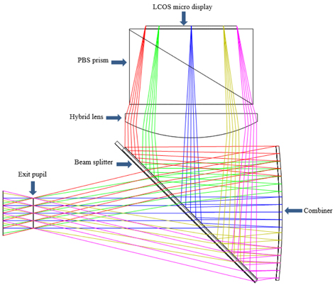
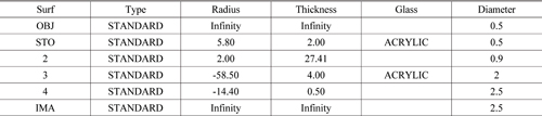
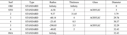
The most important part of an HMD system is its optical module. In this module, light is reflected from the DMD and projected on the combiner and combines with the external scene’s beams to construct an arbitrary image in the exit pupil. The HMD’s projector layout is shown in Fig. 7 and its lens data from ZEMAX is shown in Table 4. From Fig. 7 we can see that the HMD’s projector has six parts that include an exit pupil, a semi reflecting beam splitter, a combiner, a hybrid lens, a total internal reflection prism, and an image source. The hybrid lens is a plano-concave lens with the plane surface as the diffractive Fresnel surface, its lens data from ZEMAX is shown in Table 5.
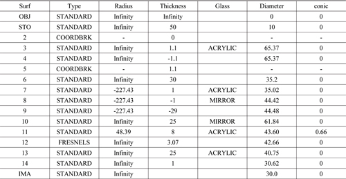
THMD’s optical module lens data from ZEMAX (unit: thickness/distance in mm, angle in degree)
[Table 5.] Fresnel surface data from ZEMAX (unit: thickness/distance in mm, angle in degree)

Fresnel surface data from ZEMAX (unit: thickness/distance in mm, angle in degree)
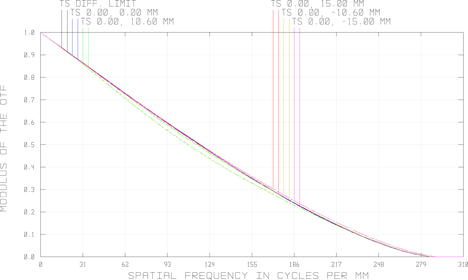
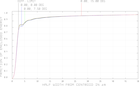
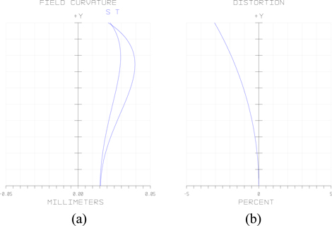
The image quality is evaluated by spot diagram, modulator transfer function (MTF), ensquared energy, and distortion aberration. The figures are shown in Figs. 8-11 respectively.
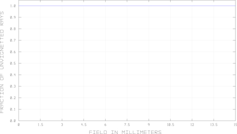
From Fig. 11 we can see that the maximum distortion and field curvature are less than 3% and 0.05 mm respectively. The maximum RMS radius for the spot diagram is 0.804 μm, which is shown in Fig. 8. In Figs. 9, 10, the MTF and ensquared energy diagrams are fit to diffraction limited. One can calculate the amount of losses resulting from stray light with vignetting diagram. As shown in Fig. 12 the amount of this loss is exactly zero, therefore the maximum efficiency will be achieved.
The optical specifications of the HMD’s optics that we designed is summarized in Table 6. A compact and diffraction limited HMD’s optical design has been implemented. Common acrylic materials were utilized in the optical design process; therefore, the final optical system was lighteight. The maximum amount of distortion aberration is less than 3%, and this amount represents the minimum distortion in field of view. We optimize PG-PCS polarization conversion module to convert an unpolarized incident beam to a uniform top hat (squared) linearly polarized light. Therefore the novelty and benefits of this design are its: lightweight, diffraction limited, high diffraction efficiency elements, the use of an unpolarized light source, and better aberration correction.
[Table 6.] Design specification
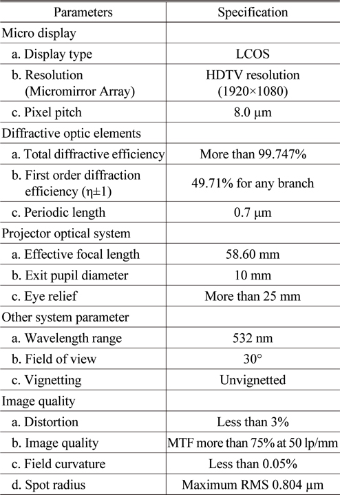
Design specification


![Specification of liquid crystal mixture [10]](http://oak.go.kr/repository/journal/21512/KGHHD@_2017_v1n2_150_t003.jpg)