검색 전체 메뉴
PDF
맨 위로
OA 학술지
Design of a Triple-Mode Bandpass Filter Using a Closed Loop Resonator
  • 비영리 CC BY-NC
  • 비영리 CC BY-NC
ABSTRACT

In this study, a novel third-order bandpass filter, which is based on a rectangular closed loop resonator, is presented. By adding a series resonator to the conventional loop resonator, the resonator’s even resonant mode is split into two modes, while the odd resonant mode is not affected. Therefore, by varying the values of the series resonator elements, the resonant frequencies of two even modes can be determined independent of the odd-mode resonant frequency. In the proposed triple-mode filter design, instead of using a lumped series resonator, a T-shaped transmission line is coupled to the resonator via a small gap. To verify the design method, a filter is designed at 2.4 GHz with a bandwidth of 100 MHz. The improved performances of the proposed triple-mode filter are compared with those of the conventional dual mode filter.


KEYWORD
Bandpass Filter , Closed Loop Filter , Splitted Even Mode , Triple-Mode
  • I. INTRODUCTION

    In the latest mobile communication system in which a high data rate multimedia service is required, a miniaturized bandpass filter (BPF) with high performance is essential. Therefore, many studies have focused on the design of such BPFs, one of which employs a closed loop resonator in which the dual resonant modes exist. Since the first presentation of the dual-mode ring BPF by Wolf [1], various innovative designs have been proposed, including the dual-mode microstrip loop resonators with circular or square shapes [26]. In [2], dual-mode resonators made of square and circular loops were introduced. In [3], a meander loop resonator was proposed to reduce its size. However, this structure becomes complicated, and interferences among the meander lines can be generated when the size reduction is excessive. The square closed loop filter was proposed in [4]. By inserting capacitive perturbation, adjusting the bandwidth of two-pole BPFs is possible. However, having a wider bandwidth with two resonators is difficult and having many resonators to cover the wider bandwidth is desirable. In general, increasing the number of the resonator to cover the wide bandwidth increases the filter size. In [5], triple-mode BPFs with transmission zeros were presented. However, the theoretical analysis was not fully discussed.

    In this study, we propose a three-pole BPF based on the square closed loop resonator. By adding a series resonator to the loop as in [5], creating a third resonant mode, which results in a three-pole BPF, and accommodating more bandwidth are possible. In case the series resonator is replaced by a T-shaped transmission line coupled to the loop resonator by a small gap, the size of the BPF remains the same as that of the conventional closed square loop resonator, which has two-pole characteristics.

    II. ANALYSIS OF A CONVENTIONAL CLOSED LOOP RESONATOR

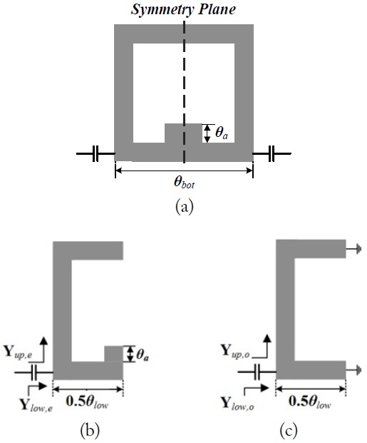
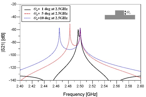
    The conventional closed loop resonator shown in Fig. 1(a) has two resonance modes [2]. The even–odd mode analysis is usually employed to analyze its characteristics. By adjusting the perturbation θa, as shown in Fig. 1(a), the electrical length of the even mode is changed to 0.5θlow + θa when measured from the feed point; the odd mode is not affected by the perturbation and its length remains 0.5θlow, as shown in the Fig. 1(b) and (c), respectively. Assuming that the total length of the resonator is λ, the electrical length of the upper line from the feeding point is π-0.5θlow for both even and odd modes. By using the even–odd mode analysis [7], the closed loop resonator’s resonance condition is given as [8]:

    image

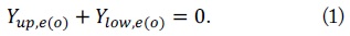
    Based on (1), the resonant conditions for the even and odd modes are derived as follows:

    image

    Without the perturbation (θa = 0), the resonance frequency of two modes are identical (θlow = λ/4). Fig. 2 shows the transmission characteristics of the resonator with varying perturbations θa at 2.5 GHz. Even if θa is changed, the resonant frequency of the odd mode remains at 2.5 GHz, as shown in Fig. 2.

    III. ANALYSIS OF CLOSED LOOP RESONATOR WITH A SERIES RESONATOR

       1. Resonant Characteristics of the Proposal Resonator

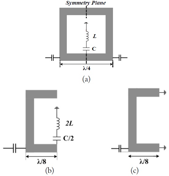
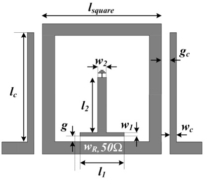
    The proposed BPF that can improve filter performances without affecting the size of the conventional closed loop BPF is shown in Fig. 3(a). It employs a series resonator as a perturbation. The even- and odd-mode equivalent circuits are given in Fig. 3(b) and (c), respectively.

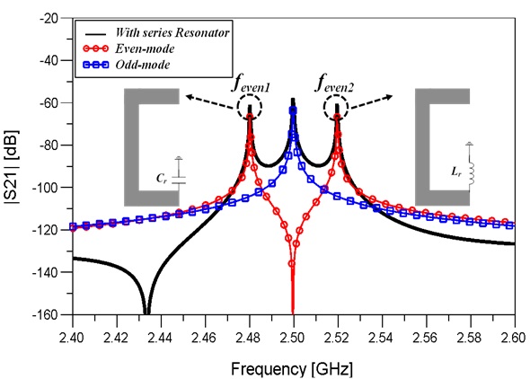
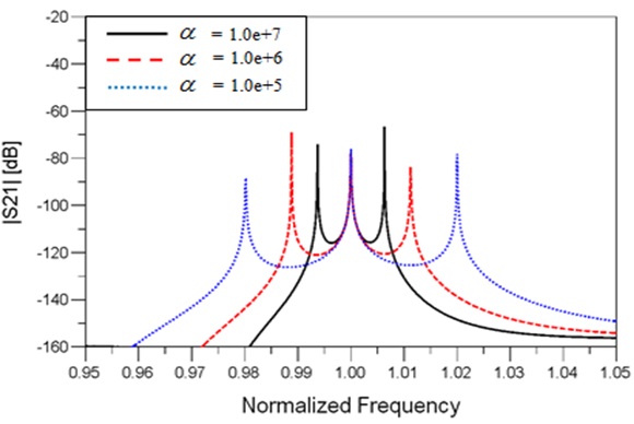
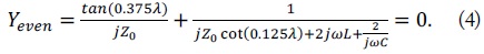
    As the odd mode is not affected by the perturbation, its resonant frequency remains the same as that of the conventional closed loop resonator, the resonant condition of which is given by (2). However, because of the LC resonator introduced as a perturbation, the resonant characteristics of the even mode are influenced in such a way that there exist two resonant modes. Their equivalent circuits are shown in Fig. 4. The resonant condition for the split two even modes is given as

    image

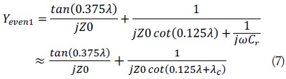
    When the resonant frequency of the series resonator is identical to fodd, the two even resonant modes are located around the odd resonant frequency f0.

    As shown in Fig. 3(b), the series resonator works as a capacitor Cr at a low resonant frequency and as an inductor Lr at a high frequency (Fig. 4).

       2. Equivalent Model of the Even Mode

    The center frequency f0 and the ratio of inductance and capacitance of the series resonator are newly defined as the following equations:

    image

    To determine the resonant frequencies, the admittances Yeven1 and Yeven2 are derived as follows:

    image

    Two resonant frequencies, feven1 and feven2, are calculated for several α using (7) and (8) and plotted as shown in Fig. 5. The coupling coefficient k between the two even modes is defined as follows:

    image

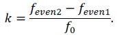
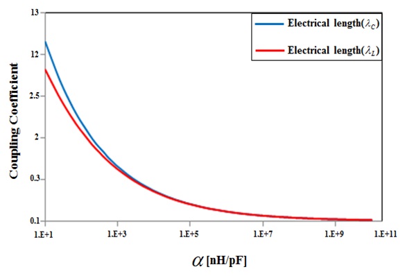
    The value of the coupling coefficient k as a function of α is shown in Fig. 6. As α decreases, the k value increases. Therefore, the proposed BPF is suitable for designing a wideband BPF. Even if the value of α is small, the lumped element circuit can be replaced with a distributed one without any difficulty.

    IV. DESIGN OF THE TRIPLE-MODE BPF

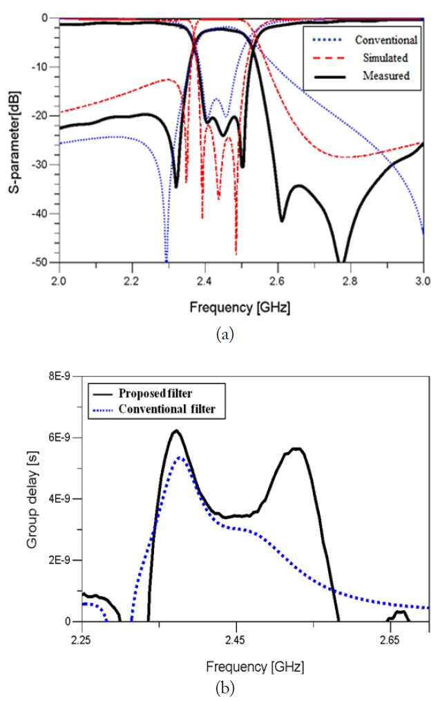
    The proposed three-pole BPF is designed at 2.4 GHz with a 100 MHz bandwidth. The 50 Ω transmission line is used except for the series resonator and the input/output coupling lines. The input/output coupling is made through a capacitor, which is replaced by the gap gc and length lc, as shown in Fig. 7 [9]. The series resonator composed of lumped elements is converted into an equivalent T-shaped resonator, as given in Fig. 7. The capacitance of the series resonator can be replaced by the gap with w1 and g, and the inductance is replaced by the T resonator with length l2 and width w2, as shown in Fig. 7. The layout of the designed filter is illustrated in Fig. 7.

    The substrate used in the design is RO3003 (εr = 3.0, tanδ = 0.0013) with a thickness of 60 mil, and the resonator size is 0.25λ × 0.25λ, which is the same as that of the conventional closed loop resonator. The measured frequency responses of the triple-mode BPF are presented in Fig. 8(a), and they show a good agreement with the simulated ones. The simulated frequency responses of the conventional dual mode BPF are also plotted in Fig. 8 for comparison. The insertion loss at passband was mea-sured as 2.3–2.7 dB, and the return loss at passband was mea-sured as greater than 20 dB. The two transmission zeros at the stopband are created by the asymmetrical feeding of the resonator [10], and the transmission zero at the upper stopband is created by the input/output asymmetrically coupled lines [9]. The proposed BPF has third-order filter responses and better skirt response characteristics. In Fig. 8(b), the group delay is also compared. The fabricated triple-mode BPF has a group delay of 4 ns in the operating frequency band.

    V. CONCLUSION

    In this study, a method for improving the conventional two-pole BPF made of a closed loop into a triple-mode BPF was proposed. The proposed three-pole BPF could accommodate a wider bandwidth than the conventional two-pole BPF without affecting the filter size. The lumped series resonator was used in the theoretical approach. However, at high frequencies, using the lumped element inductor is difficult because of self-resonant characteristics. For this reason, the equivalent T-shaped resonator was used instead of the series resonator. The size of the proposed BPF was the same as that of the conventional closed loop BPF. The proposed design method was applied to the BPF based on the closed loop resonator. The proposed scheme is expected to be applicable to other types of resonators.

      >  CONFLICT OF INTEREST

    Opinions expressed in the paper are the personal opinions of the original authors, and do not necessarily reflect those of Qualcomm Incorporated or its subsidiaries ('Qualcomm'). The content is provided for informational and academic purposes only and is not meant to be an endorsement or representation by Qualcomm or any other party.

참고문헌
  • 1. Wolff I. 1972 "Microstrip bandpass filter using degenerate modes of a microstrip ring resonator," [Electronics Letters] Vol.8 P.302-303 google cross ref
  • 2. Hassanieh H., Shi L., Abari O., Hamed E., Katabi D. 2013 "Bigband: GHz-wide sensing and decoding on commodity radios," google
  • 3. Curtis J. A., Fiedziuszko S. J. 1991 "Miniature dual mode microstrip filters," [in Proceedings of IEEE MTT-S International Symposium Digest] P.443-446 google
  • 4. Hong J. S., Lancaster M. J. 1995 "Microstrip bandpass filter using degenerate modes of a novel meander loop resonator," [IEEE Microwave and Guided Wave Letters] Vol.5 P.371-372 google cross ref
  • 5. Lee J. H., Nam H., Lim Y. S. 2012 "An enhanced skirt characteristics triple-mode filter," [Journal of Electromagnetic Engineering and Science] Vol.12 P.210-215 google cross ref
  • 6. Hong J. S., Lancaster M. J. 1995 "Bandpass characteristics of new dual-mode microstrip square loop resonators," [Electronics Letters] Vol.31 P.891-892 google cross ref
  • 7. Reed J., Wheeler G. H. 1956 "A method of analysis of symmetrical four-port networks," [IRE Transactions on Microwave Theory and Techniques] Vol.4 P.246-252 google cross ref
  • 8. Lei M. F., Wang H. 2005 "An analysis of miniaturized dualmode bandpass filter structure using shunt-capacitance perturbation," [IEEE Transactions on Microwave Theory and Techniques] Vol.53 P.861-867 google
  • 9. Matthaei G. L., Young E., Jones E. M. T. 1980 Microwave Filters, Impedance-Matching Networks, and Coupling Structures. google
  • 10. Hsieh L. H., Chang K. 2002 "Dual-mode quasi-elliptic function bandpass filter using ring resonators with enhanced-coupling tuning stubs," [IEEE Transactions on Microwave Theory and Techniques] Vol.50 P.1340-1345 google cross ref
이미지 / 테이블
  • [ ] 
  • [ Fig. 1. ]  Conventional closed loop filter: (a) basic configuration, (b) even-mode, and (c) odd-mode equivalent circuits.
    Conventional closed loop filter: (a) basic configuration, (b) even-mode, and (c) odd-mode equivalent circuits.
  • [ ] 
  • [ Fig. 2. ]  Transmission characteristics of the conventional loop resonator for various lengths θa.
    Transmission characteristics of the conventional loop resonator for various lengths θa.
  • [ Fig. 3. ]  Proposed bandpass filter: (a) a closed loop with a series resonator, (b) even mode, (c) odd mode.
    Proposed bandpass filter: (a) a closed loop with a series resonator, (b) even mode, (c) odd mode.
  • [ ] 
  • [ Fig. 4. ]  Resonant characteristics of the odd and two even modes of the proposed resonator.
    Resonant characteristics of the odd and two even modes of the proposed resonator.
  • [ ] 
  • [ ] 
  • [ ] 
  • [ Fig. 5. ]  Resonant characteristics of the proposed resonator for different values of α.
    Resonant characteristics of the proposed resonator for different values of α.
  • [ Fig. 6. ]  Coupling coefficient depending on the various values of α.
    Coupling coefficient depending on the various values of α.
  • [ Fig. 7. ]  Layout of the designed bandpass filter (wR = 3.8 mm, lsquare = 24.2 mm, g = 0.2 mm, gc = 0.2 mm, wc = 0.2 mm, w1 = 1 mm, l1 = 6.8 mm, w2 = 1.4 mm, l2 = 13 mm).
    Layout of the designed bandpass filter (wR = 3.8 mm, lsquare = 24.2 mm, g = 0.2 mm, gc = 0.2 mm, wc = 0.2 mm, w1 = 1 mm, l1 = 6.8 mm, w2 = 1.4 mm, l2 = 13 mm).
  • [ Fig. 8. ]  Comparison of the measured frequency responses: (a) S-parameters and (b) group delay.
    Comparison of the measured frequency responses: (a) S-parameters and (b) group delay.
(우)06579 서울시 서초구 반포대로 201(반포동)
Tel. 02-537-6389 | Fax. 02-590-0571 | 문의 : oak2014@korea.kr
Copyright(c) National Library of Korea. All rights reserved.