Nitrogen-atom doped graphene oxide was considered to prevent the dissolution of polysulfide and to guarantee the enhanced redox reaction of sulfur for good cycle performance of lithium sulfur cells. In this study, we used urea as a nitrogen source due to its low cost and easy preparation. To find the optimum urea content, we tested three different ratios of urea to graphene oxide. The morphology of the composites was examined by field emission scanning electron microscope. Functional groups and bonding characterization were measured by X-ray photoelectron spectroscopy. Electrochemical properties were characterized by cyclic voltammetry in an organic electrolyte solution. Compared with thermally reduced graphene/sulfur (S) composite, nitrogen-doped graphene/S composites showed higher electroactivity and more stable capacity retention.
Since its invention, the lithium-ion battery has gone through several advancements during its commercialization and application as energy source for a variety of devices. According to use, many improvements were performed and this accelerated the rapid spread of smart devices. In the case of electric vehicles or energy storage system (ESS) for smart grids, an additional development of the lithium-ion battery is required [1-3]. For example, as batteries for electric vehicles, 500 km driving on a single charge is required for full commercialization, which corresponds to energy density of 700 Wh kg−1. However, this is hard to realize because the lithium-ion battery appears to have reached the limits of its development. To solve this problem, researchers have tried to discover a next-generation secondary battery. Among many candidates undergoing intensive research, the lithium-sulfur (Li-S) battery has unusually high specific energy density (2600 Wh kg−1) and high theoretical capacity (1675 mAh g−1) [4-6]. A Li-S battery not only has electrochemical advantages, but also lower price because elemental sulfur is abundant in the environment and could get easily be provided as a by-product of existing industrialization. However, before it could replace the lithium-ion battery, several technical challenges must be met that now hamper commercialization of the Li-S battery. The poor conductivity of pristine sulfur, dissolution of polysulfide into the electrolyte [7-9], and its large volume change (>80%) during the charge/discharge process must be overcome to provide practical application [10]. An alternative way to improve the electric conductivity or stable structure of the needed electrodes would be to use carbon material as a support for the active sulfur material. The high conductivity of carbon can guarantee better electrochemical performance of cells and some carbon has a structure sufficiently strong to withstand the change in sulfur volume. For these reasons, several forms of carbon were attempted as cathode material supports. Meanwhile, since graphene was detected in 2004, its applications have become widespread [11,12]. Among many fields, ESS has great potential for the adoption of graphene as electrode material because of grapheneldrochemical performance of cell, flexibility, and stability [13-16]. Furthermore, nitrogen-doped graphene sheets (NGS) provide one of the most attractive choices for a Li-S battery due to their excellent adsorption of nitrogen atoms to the carbon matrix [17]. In this regard, nitrogen atoms are of different types depending on their position in a carbon matrix. In detail, pytidicin-N and pyrrolic-N are the main parts that enhance electrochemical performance of energy storage devices. The use of nitrogen atoms in a carbon matrix was expected to prevent dissolution of polysulfide and enhance the cycle performance of cells [18]. Because of its low cost and easy preparation, urea is generally the source of choice for nitrogen doping of graphene-based carbon materials [19,20]. Oxygen-containing functional groups in graphene oxide (GO) and amino-groups of urea are thought to be essential in the formation of C–N bonds in the graphene lattice. Nitrogen-doped graphene has been studied as an electrode material for capacitors and batteries, and as catalyst support for various types of fuel cells. In line with this concept, we tried nitrogen-doped GO from urea precursor, for electrodes of lithium-sulfur cells.
To improve the electrochemical performance of lithium-sulfur cells and to find the optimum content of urea needed to prepare the nitrogen-doped GO, we fabricated three different NGS of varying nitrogen content by facile, thermal, solid-state reaction of GO and urea. After that, a melt-diffusion technique and solution-based synthesis using carbon disulfide (CS2) were carried out to introduce elemental sulfur between the NGS [21].
Graphite powder (99.9%, 1 ppm mesh) was purchased from Bay Carbon Co., Ltd. (Bay City, MI, USA), and urea was purchased from Yakuri Pure Chemicals Co., Ltd. (Kyoto, Japan). Elemental sulfur and organic solvents were purchased from Sigma-Aldrich. Distilled water was used in all experiments. Li salts and other reagents were used at the guaranteed reagent grade.
GO was prepared by Hummer’s method. Briefly, a mixture of 1 g of graphite powder and 1 g of sodium nitrate was added to 46 mL of sulfuric acid. After that, 5 g of potassium permanganate was added to the solution and stirred at 35℃ for 2 h. Then, 220 mL of H2O and 5.2 mL of H2O2 were added. The oxidized solution was filtered and washed using HCl. The GO obtained was washed again with ethanol and H2O three times, with centrifugation (3600 r/min, 5 min). GO powder was obtained after freeze drying.
2.3. Synthesis of N-doped graphene sheets
Nitrogen-doped graphene sheets (NGS) were produced by thermal solid-state reaction using urea as the doping source for the prepared GO powder. A mixture of 0.3 g of GO and 0.3, 0.9, and 1.5 g of urea (mass ratio = 1:1, 1:3, 1:5, respectively) were ground in an agate mortar for 30 min; then heat treated in a tube furnace. The samples were designated NGS-1, NGS-2, and NGS-3. Before heat treatment, Ar gas was used to fill the tube furnace for 30 min. Then the temperature was raised to 400℃ at a rate of 5℃ min−1 and kept at the final temperature for 2 h. After cooling to room temperature, the calcined products were filtered and washed using 1 M HCl solution; then dried at 60℃ for 12 h. For comparison, we produced thermally reduced graphene (TRG) at 400℃ without any nitrogen source.
2.4. Synthesis of NGS/sulfur composites
To insert elemental sulfur between nanosheets, we used a melt-diffusion technique and solution based synthesis with CS2. First, sulfur was dissolved in CS2 and stirred for 15 min because sulfur is highly soluble in CS2 at room temperature. Then, the prepared NGS was added and the solution stirred until the CS2 solvent fully vaporized. Through this process, sulfur powder was dissolved, moved into position between the nanosheets, and became embedded by their re-crystallization. In order to the sulfur to penetrate effectively, the melt-diffusion technique (in a tube furnace) was carried out consecutively. The mixture was heat treated at 160℃ for 12 h under Ar to melt the elemental sulfur and allow it to infiltrate widely. After cooling down to room temperature, the NGS/S composite was obtained.
2.5. Structural characterizations
To investigate the surface morphology of the NGS/S composites, field emission scanning electron microscope (FE-SEM; SUPRA25; Carl Zeiss AG, Oberkochen, Germany) and energy-dispersive X-ray (Raith Elphy Quantum, Dortmund, Germany) were used. We also studied the functional groups and bonding characterization using X-ray photoelectron spectroscopy (XPS; Axis Nova). The sulfur content of the NGS/S composites was calculated based on the thermogravimetric analysis (TGA) data.
2.6. Electrochemical characterization
The electrochemical characterization was determined using a CR-2016 type coin cell. The cathode was prepared by mixing NGS/S composites (80 wt%), Super-P (10 wt%), and polyvinylidene fluoride (10 wt%) in an N-methyl pyrrolidinone. Then, the slurry was spread onto aluminum foil. Test cells consisting of a lithium metal anode, separate, and cathode were assembled in an argon-filled glove box. The electrolyte solution was 1 M lithium bis(trifluoromethane) sulfonamide salt (LITFSI) in a mixture of 1,3-dioxolane (DOL) and 1,2-dimethoxyethane (DME), with a volume ratio of 1:1.
The cycle voltammetry test measurement was conducted with an electrochemical measurement system (WonATech Co., Seoul, Korea). Cyclic voltammetry (CV) was performed in a voltage range of 1.5–3.0 V, and the scan rate was fixed at 0.2 mV s−1. Charge/discharge cycle tests were conducted using a multichannel high performance battery cycler, between the voltages of 1.5 to 3.0 V at 100 mAh/g.
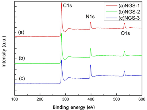
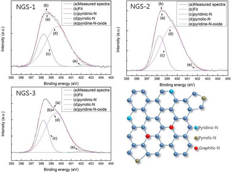
To identify the elemental composition of the different NGS composites, XPS measurements were carried out (Fig. 1). All the composites showed an N1s peak, which means that the nitrogen doping by thermal-solid reaction was successful. Two other peaks centered at about 285.0 eV and 531.0 eV, were C1s and O1s, respectively [22]. Table 1 shows the elemental composition and distribution of nitrogen species in the composites. The atomic percent of nitrogen was 12.6% for NGS-1, 16.43% for NGS-2, and 21.96% for NGS-3, which can be attributed to the amounts of nitrogen added. The high resolution N1s peaks of the composites, and the distribution of nitrogen species, are given in Fig. 2. As shown in Table 1, pyrrolic-N was predominant and graphitic-N was not observed for all composites. This was because graphitic-N was probably formed during the thermal solid reaction at 500℃ to 700℃ [19,23]. The greater amount of nitrogen content in the NGS-3 composite, and the difference in distribution of the nitrogen species, may be dependent on the ratio of urea to GO and would explain the electrochemical performance of the cells [24,25]. The atomic proportions of the nitrogen species were almost proportional to the amounts of urea added to the GO.
[Table 1.] Carbon, nitrogen, oxygen content and N distribution of NGS from XPS measurement
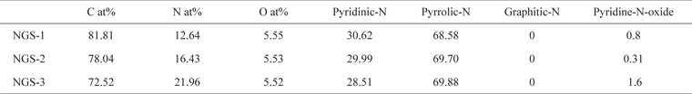
Carbon, nitrogen, oxygen content and N distribution of NGS from XPS measurement
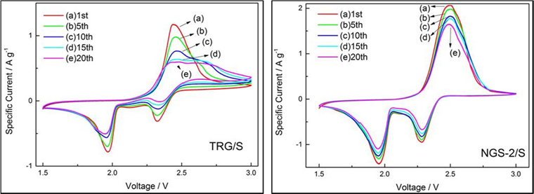
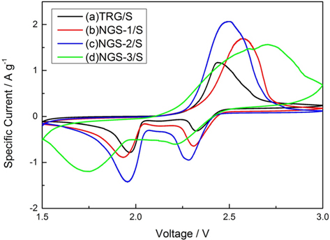
The electrochemical performance of the TRG/S, NGS-1/S, NGS-2/S and NGS-3/S composites was tested by CV and galvanostatic charge/discharge measurements. The CV graphs of composite electrodes at 1.5 and 3.0 V for the first cycle, at a scan rate of 0.2 mV s−1, are shown in Fig. 3. All of the composites showed only one oxidation peak, which means that Li2S2 and Li2S were transformed to Li2S8. Among the well-defined reduction peaks observed, some indicate the transformation of Li2S2 or Li2S to Li2S8; some the reduction of elemental sulfur to high-order lithium polysulfides (e.g., Li2S8); then to low-order lithium polysulfides (Li2Sn, 4 ≤n). Others indicate reduction of lithium polysulfides to solid-states Li2S2/Li2S [26-28]. As shown in Fig. 3, the differences in electrical potential between cathodic and anodic peaks of nitrogen doped samples increased, meaning a large polarization of the electrodes. Moreover, no peaks were observed without the redox reaction peaks of sulfur, indicating that the nitrogen-doped graphene did not have a bad influence on the redox process of sulfur. Fig. 4a and b display CVs of TRG/S and NGS-2/S cathodes during 20 cycles. The TRG/S electrode showed a gradual decrease in the intensity of the cathodic and anodic peaks. In comparison to the TRG/S cathode, the NGS-2/S electrode exhibited more stable curve overlap that confirmed the high reversibility and stability of the electrode. From this result, it was thought that the N-doped graphene electrode showed a stable redox reaction of sulfur due to the limited dissolution of the polysulfide or limited desertion from the electrode.
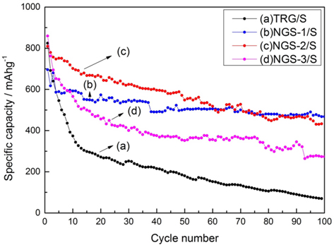
The cycle performances of all the cathodes at 100 mAh g−1 are shown in Fig. 5. All the composite electrodes showed similar initial capacity (~800 mAh g−1) but the TRG/S cathode showed a rapid decrease of capacity over 100 cycles. In contrast, the nitrogen-doped graphene cathodes maintained their specific capacity after 100 cycles. The change in the discharge capacity during 100 cycles, of TRG/S and NGS-2/S cathodes, was 824 to 70 mAh g−1 and 809 to 433 mAh g−1, respectively. Regarding the NGS-1/S cathode, the specific capacity was slightly lower than that of the NGS-2/S cathode during the initial cycles. But after 50 cycles, the NGS-1/S cathode showed a specific capacity similar to that of the NGS-2/S cathode. The NGS-3/S cathode showed higher specific capacity than did the TRG/S cathode, but was definitely lower than the NGS-1/S and NGS-2/S cathodes. This means that excessive nitrogen atoms in the carbon matrix of graphene caused poor electrochemical performance, or low utilization of the sulfur reaction.
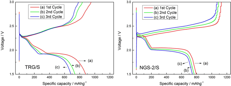
Fig. 6a and b are the charge-discharge profiles of TRG/S and NGS-2/S cathodes, respectively, at 100 mAh g−1 during the first three cycles. In both cathodes, two discharge plateaus can be distinguished in the voltage ranges of 2.2–2.4 V and 1.8–2.0 V. The first plateau corresponds to the formation of long chain polysulfides (Li2SX, 4 ≤ X ≤ 8), and the second plateau to formation of short chain Li2S2 or Li2S [29]. The second plateau is relatively longer than the first, which means that the discharge capacity is contributed by the second step of reduction. All of the redox plateaus are consistent with peaks of the CV curves. In addition, the potential plateaus of the NGS-2/S cathode are more stable and distinct than for the TRG/S cathode during the first three cycles. This means that the nitrogen doping enhances the electrochemical properties of lithium sulfur cells.
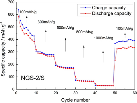
The rate capability of the NGS-2/S cathode at different rates was tested and results presented in Fig. 7. As the rates were gradually increased from 100 to 1000 mAh g−1, the discharge capacity decreased. When the current rate returned to 100 mAh g−1 the capacity of the NGS-2/S cathode recovered to 323 mAh g−1, equal to the capacity of the last cycle (100 mAh g−1). The recovery ability of a cathode indicates a stable structure and tolerance to varying current density.
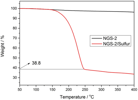
The sulfur loading of NGS-2/S composite, which showed the highest capacity, was determined by TGA. TGA (Fig. 8) shows 61.2% of sulfur loading in NGS-2/S composite, and this high sulfur content could be what provides the high overall energy density per unit mass of the cathode in Li-S cells.
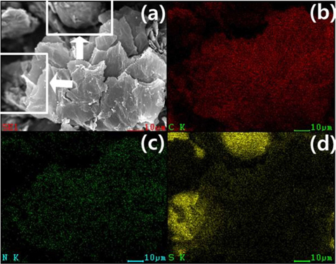
The morphology and microstructure of the NGS-2/S composite were investigated using FE-SEM. Fig. 9a shows a typical 2-dimensional plate-like structure of graphene, and a sulfur particle is indicated by an arrow. Elemental X-ray mapping (Fig. 9b-d) showed homogeneous distribution of carbon, nitrogen, and sulfur in the NGS/S composites.
In summary, NGS with sulfur loading as high as 61.2 wt% were simply synthesized using a thermal solid-state reaction. Elemental sulfur immobilized within NGS sheets was fabricated using a solution-based preparation method, followed by a melt-diffusion technique. Nitrogen doping could assist graphene in suppressing the diffusion of polysulfide by enhancing its adsorption by surface modification. The NGS-2/S cathode, which contains 16.43 at% of nitrogen, in particular, shows enhanced reversibility of the sulfur redox reaction and the best cycle stability over 100 cycles. From the electrochemical characterization by CV test, and the galvanostatic charge/discharge tests, the NGS/S cathodes showed superior reversibility and cycle stability for 100 cycles over the pristine reduced GO/S cathode. These results demonstrate that nitrogen doping of modified GO supports, improve not only the sulfur-reaction stability but also the characteristics providing longer cycling.