A new method to design a low distortion, even relative illumination, optical see-through head-mounted display (HMD) with a freeform reflective mirror (FFRM) based on the two similar ellipsoids structure is proposed. The HMD we have realized has a simple structure which consists of two similar ellipsoid surfaces, an FFRM, a 7-piece co-axis relay lens, and an OLED. This structure can be applied to offset distortion, reach even relative illumination, and correct the off-axis aberrations. The HMD we finally have realized has a near 3% low distortion, a higher than 80% relative illumination, and a 40°×30° field of view (FOV).
Developing a see-through head-mounted display (HMD) system with wide field of view (FOV), long eye relief, and low distortion is desirable for many applications, such as virtual reality, augmented reality, training and entertainment industries [1, 2]. It has been a great challenge to designers for decades, since the design process should simultaneously consider practical human use and technical requirements. A see-through HMD system usually consists of an image source, an optical relay lens group, and a combiner. The image source is used to display scenes generated by the computer. The combiner is used to provide the combination of computer-generated scenes and real-world scenes. The relay lens group is used to correct off-axis aberrations introduced by the tilted combiner [3]. There are two basic design concepts for the combiner: one is flat, often providing an on-axis system; the other has an optical power, often providing an off-axis system. The off-axis structure has many advantages: minimizing the size of the system, inhibiting the stray light, and avoiding the ghost image [4, 5]. However, the tilt combiner in the off-axis structure will introduce serious off-axis aberrations and distortion to the HMD. These off-axis aberrations directly lead to an uneven relative illumination in image. Moreover, the distortion is proportional to the FOV. An increase in FOV also means an increase in distortion. Thus, reaching a low distortion under wide FOV is very difficult. To correct the off-axis aberrations, many designers use the freeform surface as the combiner or introduce decentering and tilt in the relay lens group. For example, in 2010 Zhenrong Zheng
The two similar ellipsoids structure they first proposed is instructive to the HMD designers. On the one hand, the creative advantage of their work is that they first proposed the two similar ellipsoids structure, which has the ability to realize low distortion and wide FOV; On the other hand, the ultimate configuration they achieved consisted of 14-piece lens and has freeform surface among them, which is complicated. Moreover, they introduce decentering and tilt in the relay lens group to correct the off-axis aberrations, which would introduce extra difficulties during the manufacture and assembly process. Thus, the HMD based on this two ellipsoids structure needs to be further improved to contribute simple structure and less off-axis aberrations.
The principle of the low distortion and wide FOV properties of the two similar ellipsoids structure will be discussed in detail.
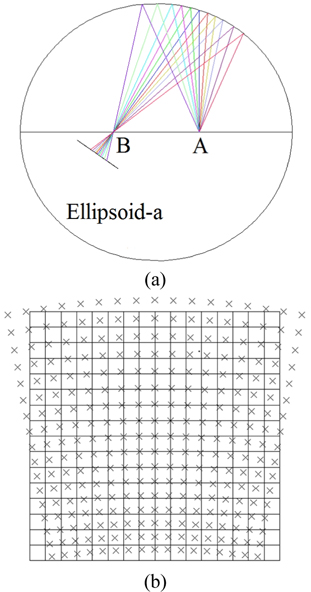
Figure 1(a) is the image property of one single ellipsoid. Point A and point B are the two foci of the ellipsoid. The entrance pupil is located at point A, thus according to the property of the ellipsoid, the chief rays of wide fields entering into the ellipsoid from point A must converge at point B after reflection by the ellipsoid surface. This image property of the ellipsoid helps to realize a wide FOV. However, as shown in Fig. 1(b), if the chief rays are only reflected by one single ellipsoid surface, a severe distortion will be introduced to the HMD according to the Scheimpflug condition [10]. Moreover, such distortion is difficult to correct by simply introducing decentering or tilt in the relay lens group.
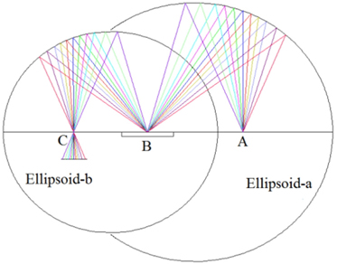
As shown in Fig. 2, in order to correct the distortion introduced by the ellipsoid-a, ellipsoid-b which has the same conic constants with the ellipsoid-a is placed after the ellipsoid-a and the right focus of ellipsoid-b coincides with the left focus of the ellipsoid-a at point B. The conic constants of the two ellipsoids are the same, but the radii of the two ellipsoid surfaces are different. The ratio of the two radii is set to be 1.5 and a flat mirror is placed at point B to make the HMD more compact and more suitable for practical use. In this two similar ellipsoids structure, the incident chief rays will in turn pass the point A, point B, point C. The distortion in the HMD introduced by the ellipsoid-a will be well compensated by the ellipsoid-b, since the conic constants of the two ellipsoids are the same, which means their distortion properties are also the same.
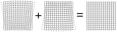
Figure 3 shows the principle of the distortion compensation in the two similar ellipsoids structure. We can see that the two similar ellipsoids have the same distortion property, thus can compensate the distortion each other while put together.
Based on the principle of using the two ellipsoids structure to reach low distortion and wide FOV, we now present a simpler HMD structure with the FFRM in the two similar ellipsoids structure. The meaning and creativity of our work is that we reach a low distortion and even relative illumination with a simpler and more compact structure. Table 1 lists the main performance parameters of our proposed HMD.
[TABLE 1.] Performance parameters
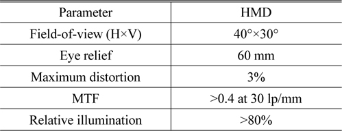
Performance parameters
As shown in Fig. 4(a), we first added one flat mirror at point B. Figure 4(b) illustrates that the distortion has been well corrected. This has well proved that the two ellipsoids structure indeed has the ability to correct distortion. However, the distortion is only related with the chief rays. The distortion can be well corrected mainly because the chief rays will pass exactly through the focal points A, B, and C after reflecting. Except for the chief rays, the rays of other fields will deviate from the focal points after reflecting and thus will cause a severe beam divergence. So, there are still severe off-axis aberrations existing in the HMD, which need to be corrected.
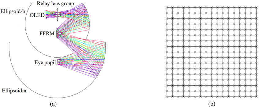
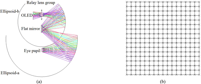
In order to correct these off-axis aberrations, we use an FFRM, which sag is x-y polynomial, to replace the flat mirror, as shown in Fig. 5(a). The use of FFRM mainly has following advantages: the FFRM won’t change the optical path of the chief rays, thus no extra distortion would be introduced to the HMD; the FFRM can restrain the rays of different fields, which benefits a co-axis relay lens group and less off-axis aberrations; the FFRM can help to reach an even relative illumination. Figure 5(b) illustrates that the FFRM can well offset the distortion.
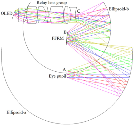
Figure 6 is the ultimate structure of the HMD we have realized. It consists of two similar ellipsoid surfaces, an FFRM, a 7-piece co-axis relay lens, and an OLED. This structure can be applied to offset distortion, reach even relative illumination, and correct the off-axis aberrations. The entrance pupil is located at point A. The rays entering into the HMD from point A will in turn be reflected by the ellipsoid-a, FFRM, ellipsoid-b, and then pass the relay lens group to image at the OLED.
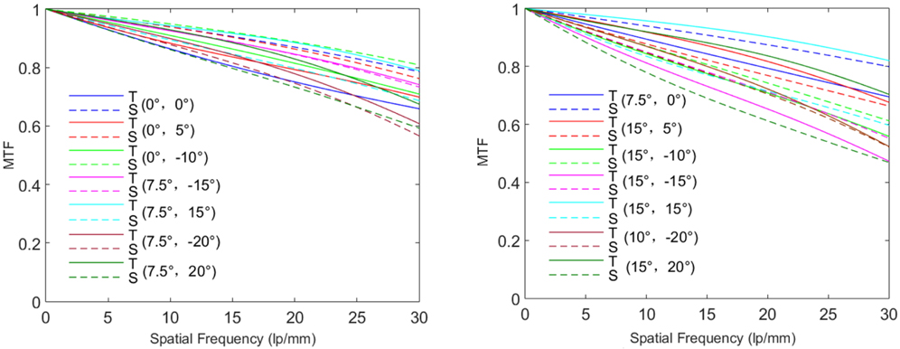
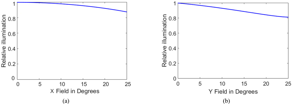
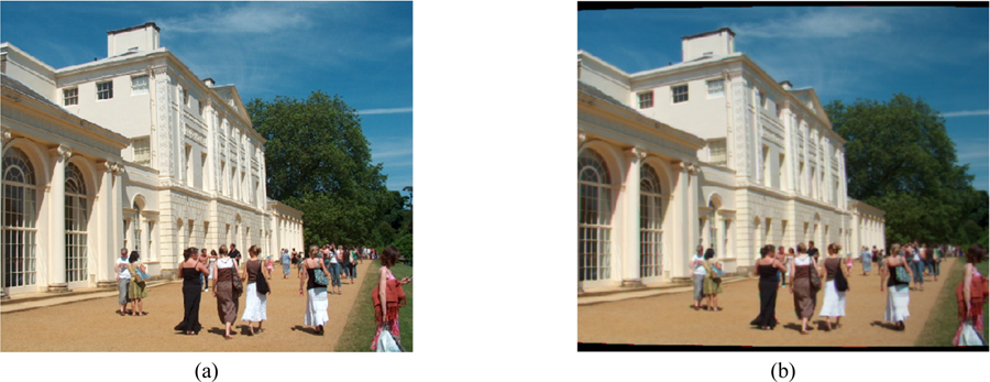
To further access the image quality of the HMD with FFRM in the two similar ellipsoids structure, we analyzed the modulation transfer functions (MTFs), relative illumination, and the 2D simulation. Figure 7 illustrates that the MTFs of the 14 fields are all above 0.4 at 30 lp/mm. Figure 8 is the relative illuminations of X-direction and Y-direction. We can see the average relative illuminations of X-direction and Y-direction are higher than 80%. Moreover, we conducted a 2D image simulation to compare the quality of the simulated picture with the original picture. As shown in Fig. 9, we can see that the distortion and chromatic aberration in the simulated picture have been effectively corrected while compared with the original image. Moreover, the simulated picture of the HMD has an even relative illumination.
In this paper, a new method to reach a low distortion, even relative illumination, optical see-through HMD with the FFRM based on the two similar ellipsoids is proposed. The HMD we realized has a simple structure, which consists of two similar ellipsoid surfaces, an FFRM, 7-piece co-axis relay lens group, and an OLED. The HMD we finally realized has a less than 3% distortion and higher than 80% relative illumination. The structure is expected to be widely used in virtual reality fields, such as training and medical visualization.