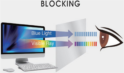
Recently, the average increase in smart phone usage times is threating the health of eyes. Average daily smart phone usage times in students and workers exceed more than three hours and that causes fatigues in most eyes. The eyes become fatigued due to the blue light generated in smart phone displays. This blue light is usually generated from crystal displays used in mobile devices, which use LED light sources such as back lights, and represents a wavelength of 390~430 nm. As eyes are exposed to crystal displays with a large amount of such blue light, the muscles of the eyes must continuously move to be focused and that causes the eye to be fatigued. In particular, as eyes are excessively exposed to the blue light, it will can cause presbyopia in early age which shows xerophthalmia with dimmed eyesight. Thus, some countries such as Japan and Taiwan have a 30% cut off rate for the amount of blue light some products can generate. In Korea, however, developments of these products are still not conducted due to the lack of recognition in the hazardousness of the blue light. Therefore, in this study a study on developing blue light cut films, which satisfy a 390∼430 nm cut off rate of more than 40% and a transmittance rate of more than 90%, was implemented using a nano micro coating system.
Figure 1 illustrates an example of the blue light.
In fabricating blue light cut films that show proper hardness, high light transmittance, and excellent cut off rate levels, developing core materials, designing and compounding hard coating, and performing coating processes are required.
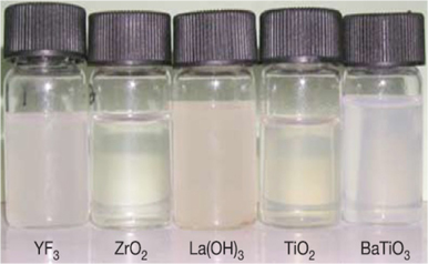
For developing core materials used in this study, the following experiment was performed. In the results of analyzing different materials such as titanium, zirconium, alumina, and nano silica, the titanium represents a milky color and that causes a problem of ensuring transmittance. In the case of the zirconium, it is expensive and that may present a problem of commercializing its products. In the case of the titanium, it shows difficulty in distributed control due to its large particle sizes. In the case of the nano silica, it is selected as a proper material because it is inexpensive and satisfies transmittance, hardness, and flexibility. As shown in Fig. 2, functional sols were fabricated using the nano silica. Also, the sols were tested and the ZrO2 was the best fit.
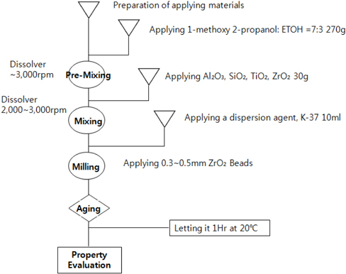
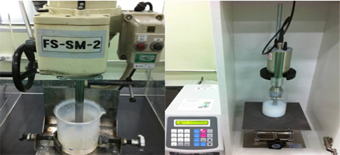
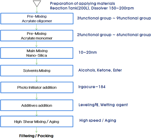
Figure 3 shows a mixing process of organic-inorganic sols using the selected function sol. The mixing was implemented for 12 hours and was aged at room temperature for 24 hours in order to maintain its distribution and solution stability. Then, a coating solution was compounded by measuring the appearance, solids, viscosity, and specific gravity of the mixture.
Figure 4 and Fig. 5 represent the mixing process of organic-inorganic sols and the compounding process of a high hardness coating solution, respectively.
A blue light cut solution was fabricated through an additional mixing process by which the blue light powder, TYD 57, was applied to the high hardness coating solution compounded through the previous process. The coating was implemented using a roll-to-roll nano micro coating system with the fabricated blue light solution. In this coating process, the UV hardening condition plays the most important role in this process. There were some breakages in coating products due to the insufficient hardening of the blue light solution according to the passage of UV hardening times. Thus, several experiments were repeated for determining the optimal condition in this process as shown in Table 1.
[Table 1.] Results of the UV hardening TEST.
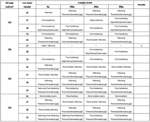
Results of the UV hardening TEST.
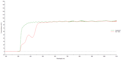
In this study, different coating processes were implemented using the blue light cut solution, which is compounded through an organic-inorganic sol-gel process. The blue light cut off rates of the blue light cut film were measured at wavelengths of 390~430 nm using a spectrometer (CM-3700d).
Figure 6 represents a trend of increasing cut off rates according to the increase in the amount of blue light cut dyes in each category. However, it showed no large increases in the cut off rates compared to the contents of dyes. In the case of the test with the lowest content, it is considered that a prescription of 0.5% is an acceptable level in its efficient point of view for applying the dye because it shows the cut off rates more than 40%. In addition, in the case of the prescription of UV99-2, tests were additionally implemented by mixing it with others because it has an effect of cutting low wavelength blue lights. In the tests, the cut off rates presented in Table 2 were used to mixing 0.5% of the blue light solution with 0.8% UV 99-2.
[Table 2.] Cut off rate for wavelengths.
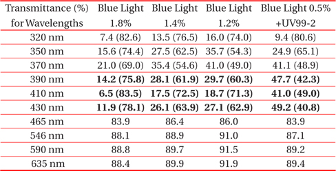
Cut off rate for wavelengths.
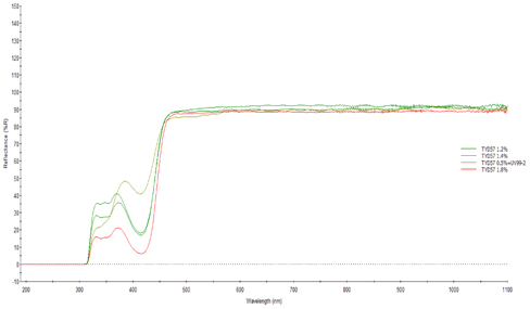
In the blue light cut off rates presented in Fig. 7, it has excellent cut off rates at 390~430 nm, more than 43% compared to that of commercial products.
Table 3 shows the numerical data from Fig. 7. It showed that the cut off rates, which are the most important factor in blue light cut films, are induced at an excellent level. Also, in the measurements of the transmittance and Haze for evaluating other functions the results are acceptable as shown in Table 4.
[Table 3.] Cut off rate for wavelengths.
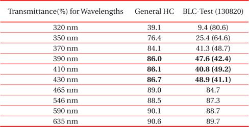
Cut off rate for wavelengths.
[Table 4.] Transmittance measurement results.
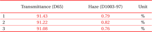
Transmittance measurement results.
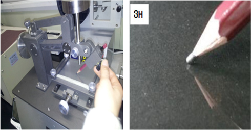
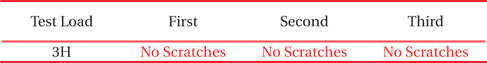
One of the important factors in films is hardness. The hardness of the fabricated blue light cut film was measured using a pencil hardness tester as presented in Fig. 8. In the hardness measurement results, it shows acceptable levels as scratches are not measured up to 3H.
[Table 5.] Hardness measurement results.

Hardness measurement results.
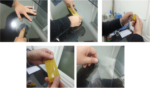
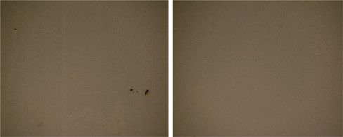
Finally, adhesive strength tests were implemented as shown in Fig. 9. The surface of the films was scratched using a cross cutter and a piece of 3M tape was attached at the scratch, detaching it. Then, an optical microscope was used to check some damaged points of the coating at the scratched point. In the results, there were no damaged and detached points as shown in Fig. 10. Thus, the coating is acceptable.
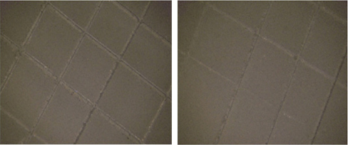
Figure 11 shows removing foreign objects (Left: foreign objects, Right: removed objects)
In summary, the development of blue light cut films performed in this study represents excellent results with the 390~430 nm cut off rates of more than 43%, the HAZE less than 1.1%, and the hardness of 3H. It is noted that there exists some foreign objects, which are dye particles on the surface of the films caused by the dispersion during its coating solution mixing process. Therefore, for improving foreign objects the mixing was performed with a mixing ratio of MEK:toluene as 1:1 instead of using the conventional method, which uses MEK only. It shows improvements in removing such foreign objects.
The blue light cut films were developed by an optimal mixing ratio and repetitional experiments. The films represent excellent blue light cut effects and homogeneous characteristics without particle residues because of its excellent dispersion. In addition, it shows advantages in the films such as excellent durability and high hardness. It is expected that it will make inroads into foreign functional film markets with competitiveness in price and quality.