In this paper, a novel full-aperture reflective null measuring method is proposed to detect the transmission wavefront of a conformal dome surface. An aspheric compensator is designed and placed behind the dome to reflect the aspheric testing wave back to the same path. To ensure the feasibility of this method, tolerance analysis is conducted, and guidance to assembly is given accordingly. The accuracy of this method is verified to be λ/30 (λ =3.39 μm) by Monte Carlo algorithm. In addition, the influence of different error factors, including the thickness error and decenter error of the dome, on the testing wavefront is analyzed. Simulation and experiment indicate that this method is practical and simple, and can measure the conformal domes precisely and comprehensively.
When a missile conducts a high-speed flight in the atmosphere, the aerodynamic heating effect and pneumatic pressure can cause the local deformation of the missile dome, which affects the detector imaging. In order to enhance the missile performance, the conformal windows with ellipsoid forms are developed. The conformal optical domes with high steepness not only reduce the aerodynamic drag and radar cross-section to enhance the weapon effectiveness, but also benefit the flexibility of the optical design; as a result, the imaging and sighting performances can be improved [1-3]. Fineness ratio, which means the length-diameter ratio, is a key index to describe the aspheric extent of conformal domes. The fineness ratio of conformal domes is usually large, up to 1:1 or even more. With the conformal domes getting steeper, conventional testing methods for common aspheric surface are no longer applicable. Besides, the optical functionalities of the conformal domes require micron or even submicron form accuracy. Therefore, the high steepness and high precision features make the fabrication and testing processes more challenging [4-6].
In general, the testing methods of conformal windows can be divided into two kinds in: contact type and noncontact type [7]. The contact methods, such as stylus profilometer or 3D profile rotary measuring instruments, scan the segmented surfaces of domes by a probe. These methods have low precision due their matching errors and reconfiguration errors in segmentation detection [8-11]. In contrast, the conventional non-contact sub-aperture measuring methods divide the surfaces into many segments and stitch the wavefront maps together. But they are not suited for the measurement of high steepness and large aperture aspheric surfaces [12]. Another non-contact method called Offner null test can effectively evaluate the overall dome surface by measuring the wavefront of dome with one measurement. At present, offner refractive null test is mainly used to test dome surface with two refractive compensators and a spherical mirror [13-15].
However, the Offner refractive null test has the disadvantage that the fabrication precision of refractive compensator can’t meet the required degree of accuracy due to the material refractive uniformity [16]. What’s more, this method needs too many auxiliary optical elements, which leads to the difficulty in assembly. Both disadvantages have effects on the accuracy of conformal dome measurement.
A new method, called full-aperture reflective null test, improving the highly aspheric domes measurement with simple structure and high testing accuracy is proposed in this paper. With this method, the reflective aspherical compensator is the only auxiliary optical element, thus the error sources are highly reduced and the measuring system is easy to assemble. Besides, the reflective aspherical compensator can be processed with high precision, which benefits the accuracy of dome measurement a lot.
II. THEORY OF FULL-APERTURE REFLECTIVE NULL TEST
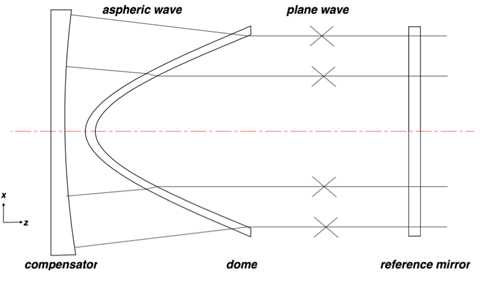
Null testing method is often used to detect the aspheric surfaces. The compensation effect of aspheric wavefront is directly determined by the processing accuracy of compensator, which is a crucial auxiliary optical element in this method. By extending the Offner’s reflective compensator principle [17], a full-aperture reflective null test capable of testing a highly aspheric conformal window can be achieved. The basic null optical system was composed of four parts: the aspheric reflective compensator, the conformal dome, the reference mirror, and a MIR interferometer which transmits and receives the plane wavefront. A layout of the optical system is shown in Fig. 1 with the interferometer aperture not shown off to the right of the reference mirror. Because the asphericity of dome transmission wavefront is moderate, the compensator can be set behind the dome directly to nullify the aberration.
As shown in Fig. 1, the plane wave which comes from a MIR interferometer goes through a reference lens. One part of the plane wave is reflected as reference wave; the other part becomes the aspheric wave after getting through the conformal dome. An aspheric compensator is designed to reflect the aspheric wave back in the same path, and the reflected beam can become a plane wave after transmitting through the dome twice. If the dome under test contains form error, the transmission wave will be distorted. When it is merged with a plane reference wave in a Fizeau MIR interferometer, fringes will appear. The ray trace shows that the entire clear aperture of the dome is measured by the collimated interferometric beam comprehensively at once. The reflective compensator can be fabricated to a high precision. Due to the simple structure, it can greatly reduce the number of auxiliary optical elements and depress the difficulty of assembly.
III. FULL-APERTURE REFLECTIVE NULL DESIGN
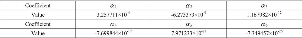
An elliptical conformal shape dome with 120 mm diameter and nearly 1:1.5 fineness ratio is measured in this paper. The full-aperture reflective null testing system is simulated and the configuration of the corresponding compensator is optimized by ZEMAX. The result suggests that the compensator is an even aspheric surface and the surface equation is as follows:

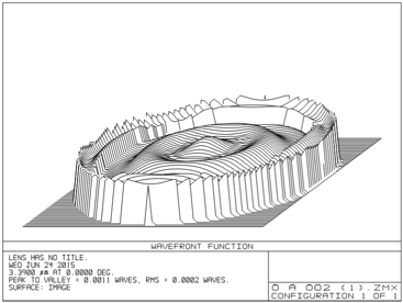
Figure 2 shows the residual wavefront error after optimization of the null testing system. The wavefront error has PV=0.0011 λ and RMS=0.0002 λ. However, it is inevitable that a variety of system errors, such as assembly errors (tilt/decenter/defocus) and compensator form error will be induced. These errors will have an impact on the interferometric pattern, subsequently affecting the measurement of conformal dome. Therefore it is necessary to make a tolerance analysis to verify the testing accuracy and the reliability of this method. In this analysis, we assume that the wavefront measuring accuracy of λ/30 rms (λ=3.39 μm) is acceptable.
[TABLE 1.] Coefficient of the compensator surface equation

Coefficient of the compensator surface equation
The conformal domes require micron or even submicron form accuracy, while the measuring accuracy of full-aperture reflective null testing method should be higher than the dome fabrication accuracy requirement. Therefore, we assume that the wavefront measuring accuracy of
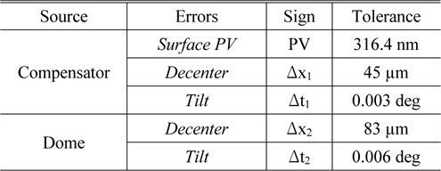
The system errors include: the compensator surface PV error PV, the defocus error between the dome and the compensator Δz, the compensator decenter error Δx1, the compensator tilt error Δt1 and the dome decenter error Δx2, the dome tilt error Δt2. Then the influence of various errors on the testing wavefront rms is analyzed. Because the conformal dome and aspheric compensator are both rotationally symmetric, different directions of decenter errors and tilt errors are equivalent. Hence the analysis procedure can be greatly simplified.
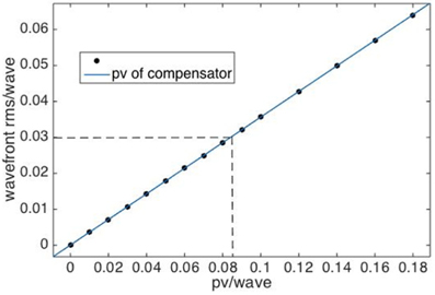
The compensator is the only auxiliary optical element. The quality of the compensator surface is directly related to the testing accuracy, so higher surface quality is preferred. However, the higher processing precision of the compensator could cause higher cost and processing difficulty. As a result, we should limit the PV error of compensator in a reasonable range. Figure 3 shows the line fitted by many separated points. The RMSE is 4.806×10⁻⁵ and the R-square is 1, which means that the line is well linear. The testing wavefront rms values are proportional with the compensator surface PV values. In order to achieve
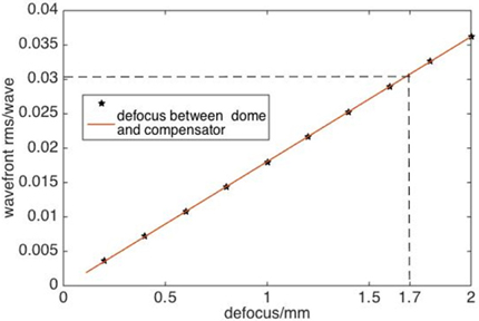
Figure 4 indicates that the fitting line is also well linear. The RMSE is 4.268×10⁻⁵ and the R-square is l. Under the requirement of λ/30 testing accuracy, the tolerance of the defocus errors between the dome and the compensator can be relaxed up to 1.7 mm. So the wavefront rms value is insensitive to defocus error and this error can be neglected. During the adjustment process, there is no need to set a high precision on the distance between the dome and the compensator.
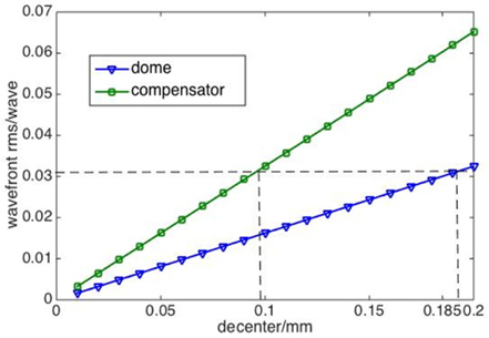
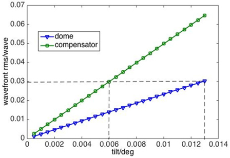
The graphs in Fig. 5 and Fig. 6 show the influence of the decenter and tilt errors of compensator and dome on the rms parameters of the testing wavefront. These curves are almost linear, and the slopes of the two lines in Fig. 5 are 0.300 and 0.162, and the slopes of the two lines in Fig. 6 are 5 and 2.307. In order to meet the accuracy requirement of λ/30, the requirements on manufacturing and assembly accuracies can be determined:
Δx1 < = 100
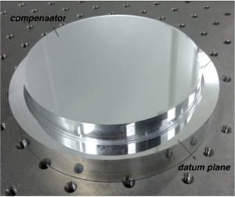
It is obvious that the line slopes of the compensator errors are almost twice of the dome errors. That is to say the testing wavefront rms is more sensitive to the compensator error than the dome error. Therefore in the process of adjustment, the assembly precision of the compensator should be controlled with a tighter tolerance. A datum plane can be processed around the compensator surface. The compensator is adjusted according to the interferometric fringes induced by the reference plane. When there are no fringes, we can think the compensator is at the right position. As for the assembly order, the compensator should be adjusted first for its high sensitivity, and then the dome is adjusted till the interferometric fringes become sparse.
In summary, there are five main error factors affecting the testing wavefront rms at the same time. Based on the uncertainty analysis, we obtain the synthetic error of the proposed method:

In the equation σ1~σ5are the standard deviation of the wavefront errors caused by the five error factors, respectively. If the synthetic testing wavefornt rms is required to be λ/30, the errors should be equally divided between the five factors. Then the final tolerance analysis results are shown in Table 2.

Tolerance range
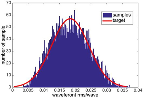
Using the Monte Carlo algorithm, we implement simulations 5000 times. As Fig. 7 shows, the histogram suggests that the rms of the testing wave is of a normal distribution and 98% of the wavefront rms values are less than λ/30. It is obvious that the tolerance range in the Table 2 have a high reliability to guide to assembly. In addition, the precision required on the fabrication and assembly can be achieved, so the feasibility of the full aperture wavefront testing method is proven.
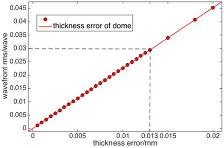
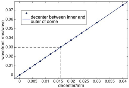
The full aperture interferometric method measures the transmission wavefront to assess the conformal dome surface. However, the thickness error and decenter error between the inner and outer surface of dome also have influence on the wavefront. If the wavefront rms were too sensitive to these two errors, it would be hard to distinguish which error induces the wavefront aberration, thus adding complications to the conformal dome measurement. We don’t expect these two errors interfere with the assessment of dome-shape-induced wavefront errors. As a result, the measuring results are desired to be insensitive to dome thickness and decenter errors. Therefore, the influence of the thickness error and decenter error between the inner and outer surface of the dome on the wavefront rms is analyzed. For the purpose of this paper, we still adopt the criterion λ/30.
As shown in Fig. 8 and Fig. 9, the lines have good linearity with 1.553×10⁻⁵ and 2.26×10⁻⁵ RMSE respectively. Both line’s R-square is 1. The test can tolerate a 13.2 μm thickness error and a 16 μm decenter error under the limit of λ/30 measuring accuracy. Compared with the fabrication precision, these errors are well within the tolerance to the fabrication of the conformal domes. As a result, we have a conclusion that when using this testing method, the thickness error and decenter error will not significantly interfere with the assessment of the dome-form-induced wavefront errors.
VI. RESULTS OF DOME MEASUREMENTS
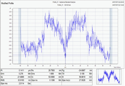
In order to validate the reliability of the full-aperture reflective null test, the conformal dome, which has been simulated and analyzed in Zemax, is measured. A reflective compensator is manufactured for the corresponding dome with the surface equation 1 requirement is shown in Fig.10. A datum plane added around the compensator benefits the precise assembly. The surface of the compensator is detected by Taylor Hobson stylus profilometer. As the report shows, the surface PV of 141.1 nm is within the tolerance of compensator surface PV of 316.4 nm, which implies that this compensator is a well-manufactured element and can be applied to test the aspheric wavefront.
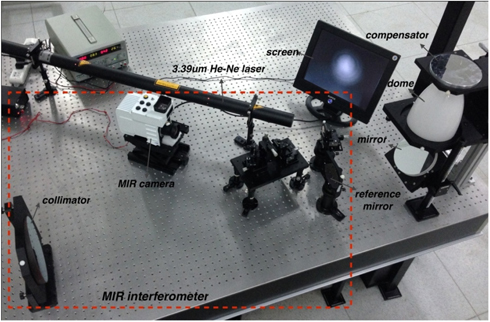
The head face of the dome, about 100 mm diameter, is the critical area to guarantee the aerodynamics and optical performance requirements, so we devote our effort on testing this part of dome. Figure 12 shows the conformal dome measuring system with the full-aperture reflective null method. The Fizeau MIR interferometer is developed with a 3.39 μm He-Ne laser and a HgCdTe MIR camera.
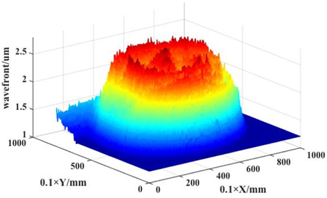
Regarding to the clamping method to dome, we adopt the vertical support way for the adjustment convenience. After the adjustment as the guidance, an interferogram in screen is worked out as shown in Fig. 12. The wavefront goes through the dome twice and we detect the inner and outer surface of dome at the same time. At last, the wavefront result in Fig. 13 suggests that the surface of the dome we tested has been fabricated well. Consequently, it shows that that the full-aperture reflective null testing method can be utilized to solve the surface measuring problem of high-gradient conformal domes precisely and effectively.
This paper puts forward a novel full-aperture reflective null measuring method to test the wavefront of the conformal dome surfaces. This method has an advantage that the full aperture can be tested comprehensively by one measurement, and the simple structure greatly reduces the number of auxiliary optical elements and diminishes the difficulty of adjustment. Besides, tolerance analysis is conducted to confirm the testing accuracy of this method. The influence of different errors, including the thickness error and decenter error, on the testing wavefront rms values is analyzed, and then guidance to assembly is given accordingly. It is proven that this method is applicable to test highly steep conformal domes with