Over the past few years, the volume of data traffic and the extent of signal processing in communication networks have grown rapidly, and transport bandwidth has continuously increased. Optical communications have attracted attention as a means to achieve broad bandwidth, large capacity, and high-speed transmission. Optical network technology is a key by which to realize next-generation communications that can provide broad bandwidth, high-speed transmission, and high-quality service to subscribers. Optical access networks are the most innovative way to improve network performance and effectively meet subscribers’ demands for high-quality broadband service. Several access network structures possessing the advantages of cost efficiency, high-speed transmission, large capacity, long-reach and large separation rates [1], high resource efficiency [2], strong survivability, and energy efficiency [3] have been proposed. Passive optical networks (PONs) have been widely deployed as flexible, scalable optical access networks in recent years. Time division multiplexing (TDM) PONs [4], wavelength division multiplexing (WDM) PONs [5, 6], optical orthogonal frequency division multiplexing (OFDM) PONs [7, 8], and TDM/WDM PONs [9] are all interesting candidates for next-generation access networks, and have been researched widely.
TDM PONs, such as IEEE802.3xx GE-PON and ITU-T G.984 GPON, have been actively deployed worldwide as basic access networks that provide low cost and high reliability, through one-to-multiple point connections via a power splitter between the remote node (RN) and optical network units (ONU). A TDM PON system is allocated time slots that are divided by a time-domain scheduling algorithm between the RN and multiple ONUs; only one ONU can transmit and receive each time slot. The downstream is a simple broadcast channel by the passive splitter, and the upstream consists of the TDM access control structure, to prevent data collisions [10]. However, a TDM PON requires complex scheduling tables to control data traffic in the upstream and downstream. As such, a TDM PON is limited in terms of transmission capacity, separation rate at RN, resource efficiency, and energy efficiency.
WDM PON technologies use multiple wavelengths to carry upstream and downstream data traffic overlapped over a single fiber between an optical line terminal (OLT) and ONUs. A WDM PON has merit in terms of larger total capacity, wider coverage, higher resource efficiency, and power savings. Because subscribers use an inherent wavelength channel assigned to each ONU, a WDM PON can provide multiple services through numerous ONUs. However, this leads to higher system costs and complexity, due to the increased number of transmitters and receivers and arrayed waveguide gratings (AWGs). In addition, a WDM-PON lacks the flexibility to allocate bandwidth resources among several services, and it is difficult to change wavelengths due to the specific wavelength channel of the ONU. WDM technologies have been advancing gradually, and presently there is a trend of combining different PON systems to provide good service to a large number of subscribers requiring broad bandwidth, large capacity, high-speed transmission, high reliability, and so on [11].
Orthogonal frequency division multiplexing access (OFDMA) has been examined as a PON because of its flexible bandwidth allocation and provision, and high-throughput data rates by parallel transmission methods, including partial overlap [12]. The bandwidth can be divided into orthogonal frequency-domain subcarriers and time-domain slots, and each ONU can be assigned one or more subcarriers in a time slot [13]. The OLT both controls domain bandwidth resource allocation and communicates with the ONUs. However, each ONU requires a different wavelength, as in a WDM-PON, to avoid the broadband beating noise that is generated by mixing between optical carriers.
A hybrid system, TDM/WDM, has been reported in recent years as an extended-reach optical access network [14]. This system combines the flexible bandwidth allocation of the TDM-PON with the large capacity of the WDM-PON [15]. This hybrid optical access network system is expected to reduce costs and provide large data capacity via high-speed transmission to subscribers. The TDM/WDM-PON cannot change the wavelength assigned to each ONU during operation, but the wavelengths can be changed according to the variable data traffic at the RN. The TDM/WDM-PON distributes an optical signal via passive splitter at the RN, which then broadcasts wavelengths assigned to each ONU [16]. As a result, the ONU requires a tunable receiver to process the multiple wavelengths coming to its input port, a security layer to protect the subscriber’s information, and a tunable transmitter as a WDM PON [17]. The tunable receiver and transmitter lead to complex control architecture, and increase the cost of the ONU.
In this paper, we present an OATM/WDM optical access network, which broadcasts data on a single wavelength from a single AWG output port inside the RN to multiple ONUs via the router. This optical access network uses a simple router, based on an optical decoder that analyzes header bits by hardware. In addition, this system is completely reconfigurable, and enables intrinsic reliability, cost efficiency, high speed, large-capacity transmission, and elevated information security. The wavelengths are transmitted to the AWG over a feeder fiber that connects the RN and OLT. The router analyzes a header using hardware structure at the RN, and optical signal outputs from the router are sent to switches on the path to deliver data allocated to each ONU. The hardware decoder technology inside the router is key to meeting the requests of subscribers in OATM/WDM optical access networks. A single router can form a secure connection with more subscribers and less power loss than the splitter used by a TDM/WDM PON for a single ONU group. In addition, the OATM/WDM hybrid system transmits data in real time, and provides higher information security, cost efficiency, and power preservation than a TDM/WDM, while maintaining high reliability. Our experiment tests header recognition for delivery to 16 and 32 ONUs with a single wavelength output from one port of AWG at the RN. The number of ONUs that can be connected using a single wavelength is increased to 64, 128, 256, 512, 1024, and 2ⁿ according to increases of 6, 7, 8, 9, 10, and
II. ARCHITECTURE OF THE OATM/WDM OPTICAL ACCESS NETWORK
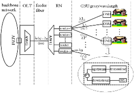
Figure 1 shows the architecture of an OATM/WDM optical access network, composed of feeder fiber and RN between the OLT and ONU. The wavelengths dropped over the add-drop multiplexer (ADM) from the backbone network are sent to the OLT. The routers, which deliver data between a single arrayed waveguide grating (AWG) inside the RN and multiple ONUs, are connected to the OLT through bidirectional feeder fiber. The OLT transmits multiple wavelengths to the AWG inside the RN. Each router then broadcasts the data according to the header assigned to a single ONU group, which uses a single wavelength, because each output port of the AWG inside the RN sends only one wavelength to each router. Therefore, the number of ONU groups is determined by the number of AWG output ports. The number of header bits recognized by the decoder inside the router determines the number of ONUs for grouping. The ONU consists of an upstream link, which transmits subscriber data, and a downstream link that includes a photodiode for receiving data. The hardware structure of the OATM/WDM optical access network can sustain sufficient bandwidth per subscriber, and its large capacity and security are better than those of conventional PONs. Thus, the OATM/WDM serves as an excellent candidate for the realization of next-generation communications.
2.1. Configuration and Router Operating Principle
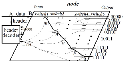
The optical header decoder inside a router plays an important role in optically routing one to multiple ONUs in a single ONU group. The optical decoder hardware analysis method that uses a single wavelength in a single ONU group is a very attractive means for data routing, because it is free from the dispersion problems caused by multiple wavelengths. In such a system, the router does not require wavelength conversion or a scheduling table to match code during routing. The output of the decoder is assigned to a slot in the time axis, according to the header information. Each optical signal output from the arrayed decoder output lines is represented as one among the many time slots in the time domain. The proposed decoder has a very simple structure, consisting of only parallel delay lines and switches. The delay-line group can be constructed of optical waveguides using the planar lightwave circuit (PLC) technique. If the number of header bits increases to 10 or 12, then the decoder is comprised of a parallel connection of two 5- or 6-bit decoders, respectively. The number of required switches and delay-line groups equals the number of header bits. Figure 2 shows the configuration of routing by a header decoder. We describe data routing with 5 header bits (11111) in the node, which has 32 output ports. The destination of the data becomes the output port (11111) in the node, and the data are switched into a cross port by the control signal at every switch. The header and data are separated at A and injected into the A and B input ports respectively [18]. To route data to its destination, the header decoder analyzes the header’s information: It analyzes the header bits and outputs a single signal from the 32nd output port. This output signal is assigned to each of the decoder’s output ports, according to the time delay inside the decoder. The decoder’s output signal is split into 5 control signals and applied to switches m, n, o, p, and q that correspond to the routes along which data pass in the node. The data are then cross-passed sequentially at switches m, n, o, p, and q. In the end, the data should arrive at the destination (11111) port. This experiment was carried out to verify the operating principle of the decoder.
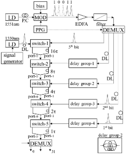
Figure 3 shows the experimental setup for 5-bit (10011) recognition. It consists of optical sources at 1550 and 1551 nm, a polarization controller (PC), an optical intensity modulator, a 1-nm bandpass filter, an erbium-doped fiber amplifier (EDFA), a 1×5 demultiplexer (DMUX), and the switches. A 1551-nm optical signal is injected into the optical modulator through the polarization controllerwhich adjusts the polarization of the optical signal going into the optical modulator.
The 1st, 2nd, 3rd, 4th, and 5th bits may be determined from the rightmost bit. The 1st, 2nd, 3rd, 4th, and 5th header bits are amplified by the EDFA, divided by the DMUX, and applied as control pulses to switches 5, 4, 3, 2, and 1, respectively. The 5th bit is sent without a branch line to switch 1, but the 4th, 3rd, 2nd, and 1st bits pass optical branch lines. The 4th bit is divided into two by delay group 1, including a branch line delayed 0t and 16t. The 3rd, 2nd, and 1st bits are respectively divided by each delay group into 4, 8, and 16, which respectively have the delay lines 0t, 8t, 16t, and 24t; 0t, 4t, 8t, 12t, 16t, 20t, 24t, and 28t; and 0t, 2t, 4t, 6t, 8t, 10t, 12t, 14t, 16t, 18t, 20t, 22t, 24t, 26t, 28t, and 30t. Conversely, a 1550-nm single optical signal is input to the switch. Each switch has two output ports; port 0 has no delay line, and port 1 is composed of a delay line. The output port 1 for switches 1, 2, 3, 4, and 5 has the delay lines 16t, 8t, 4t, 2t, and 1t, respectively. The single optical signal is switched to a bar or a cross port, depending on the information contained in each bit when the data pass every switch. That is, each bit propagates toward the bar or the cross port of switch 1 when the 5th bit is 0 or 1, respectively. The single optical signal transmits to port 1 through the 16τ delay line when the control pulse is applied to the switch; if no control signal is applied, the input signal is sent to port 0 without delay.
As an example, let us consider the recognition of the header bits (10011). Since the 1st and 2nd bits are 1, the optical output signal is delayed by 1t in switch 5, and 2t in switch 4, compared to the reference signal. The optical signal outputs from each port 0 in switches 2 and 3 have no delay time. The optical signal output through port 1 in switch 1 is delayed by a 16t delay line; thus the signal is delayed by 19t in total. As a result, the optical signal output in switch 5 is assigned to the 20th time slot, and is split into three control signals. These optical signals are applied to each switch (switches 1, 4, and 5 in Fig. 2) in routes where data pass.
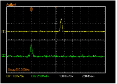
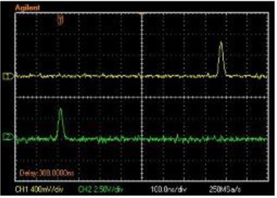
Figure 4 shows the result of the recognition of 4 header bits (1001). Lines 1 and 2 represent the output signal and the reference signal respectively. In this experiment, the delay time t = 40 ns. The total delay time between the reference and output signals is 360 ns (9t). This means that the header of the optical data represents the 10th destination, and the data must be sent to the output port (1001). Delay time t can be controlled by the PLC technique or the length of the optical fiber, according to the header bit rate.
Figure 5 shows the result of the recognition of 5 header bits (10011). The period of the header is 1 μs. Lines 1 and 2 represent the output signal and reference signal respectively. The total delay time between the reference and output signals is 760 ns (19t). The header (10011) of the optical data shows the 20th output port, and the data must be sent to the output port (10011) shown in Fig. 2. The output optical signals in Figs. 4 and 5 are divided into two and three signals, respectively, to be used as control signals for controlling the switches in routes where data pass toward the destination ONU.
In this section, we discuss the delay time
As an example, let us assume that an optical access network supports 100 Gbps in the downstream direction, at a single ONU group consisting of 1000 subscribers. The period of data and header bits is 10 ps. We assume that the full wave half maximum (FWHM) of each bit is less than 5 ps, and the minimum interval t of a single optical signal output from the decoder is 5 ps. The minimum recognition time for two 5-bit decoders for each of the 32 time slots in the recognition of 10 bits is less than 200 ps, including the time required to pass the switch. This means that the optical fiber line between the header decoder and input port B, shown in Fig. 2, needs an additional length of only 4 cm. The control signal output from the header decoder is synchronized with the 1st bit of data at each node switch, and data can be transmitted in real time over the optical access network.
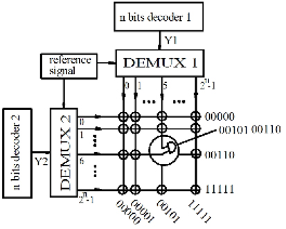
Figure 6 shows the decoder that processes the 2
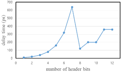
Figure 7 represents the delay time for the recognition of header bits in the decoder against a number of header bits or ONUs inside a single ONU group. If the decoder performs the recognition process in parallel when the header is 8 bits or more, the delay time increases to 7 bits; however, it decreases when processing in parallel is from 8 bits to 15 bits. Thus, the parallel decoder reduces the delay time for the header recognition.
In this study, we demonstrated an OATM/WDM optical access network, which broadcasts data from the RN to multiple ONUs by a router using a single wavelength in a next-generation optical access network. The decoder technology based on the hardware structure is key to satisfying the requests of subscribers in the OATM/WDM optical access network. We carried out recognition experiments with 4 and 5 header bits for delivery by hardware to 16 and 32 subscribers respectively. The experiments demonstrated the successful operability of the proposed header-bit decoder. We propose that this system will be instrumental in realizing a next-generation optical access network that exhibits high reliability, cost efficiency, high speed, large transmission capacity, and high information security.