Laser shock peening (LSP) is a cold metalworking process that uses high power laser pulses to generate plasma shock waves by hitting a metal surface [1]. Laser-induced plasma shock waves produce residual compressive stress causing plastic deformation in the target [4]. The LSP can improve metal properties such as surface hardness, abrasion durability, corrosion resistance, and fatigue strength [1-6]. In general, the conventional laser beam shape is close to circular. The circular beam leads to nonirradiated areas and overlapped areas. The two types of areas have disadvantages with regard to the efficiency of the LSP [7, 8]. A square beam is required to reduce the area and increase the efficiency [1, 7-11]. In addition, the LSP becomes inhomogeneous owing to the nonuniform intensity distribution within the laser beam. A uniform beam distribution is also required to homogenize the plasma area peened by a laser beam. Therefore, a square beam homogenizer is required to enhance the efficiency of the LSP and to improve the peening quality simultaneously.
The working distance (WD) of a square beam homogenizer is important in the view of the industrial application of the LSP. The long WD, which has various height targets, makes peening possible without any unnecessary movement in the beam homogenizing system. It is related to the depth of focus (DOF) of the square beam homogenizer. We need to analyze the DOF of a square beam homogenizer in order to maximize the WD and increase the efficiency of the LSP. However, the DOF in the case of the LSP (LSPDOF) is different from the conventional DOF considered in most optical systems, which implies the tolerance of placement of the image plane in relation to the lens, as LSP-DOF must include the concept of plasma threshold. There are two perspectives about WD: spatial uniformity and efficiency. The LSP-DOF means WD for the industrial application of LSP in terms of efficiency.
In this study, we defined the LSP-DOF using the efficiency of the LSP, which is defined as the ratio of the energy in the peening area to the energy in an input beam irradiated area. We found the relationship between the LSP-DOF and four parameters of the square beam homogenizer: the plasma threshold intensity (Ith) of the metal, the number (NAL) of lenslets in the array-lens, the focal length (fC) of the condenser lens and the input beam size (Din).
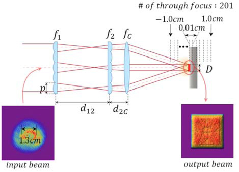
To simultaneously reform the beam shape and distribution, we selected a multi-aperture beam homogenizer, which consists of two positive array-lenses and a condenser lens [12, 13] (Fig. 1). The first array-lens, with square lenslet, divides the incident beam into several square beamlets. These beamlets are relayed by the second array-lens, which has the same specifications as the first array-lens. The condenser lens superposes all the beamlets, and the square beam is generated at the target plane.
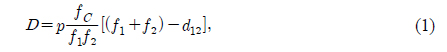
The final square image size is given as [12, 13]
where p is the pitch size of the array-lens, d12 is the distance between the two array-lenses, and f1, f2, fC are the focal lengths of each of the lenses (Fig. 1). The final image size D is obtained from the magnifying power , where feq is the equivalent focal length of two array-lenses .
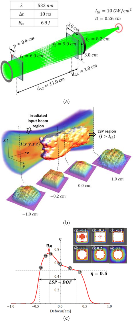
The beam homogenizer was configured in CODE V, a lens design program. With the illumination analysis tool of CODE V, we obtained the 201 beam distributions near the target from −1.0 cm to 1.0 cm at intervals of 0.01 cm (Fig. 1). Then, the plasma threshold was applied to the given beam distributions. The circular and nonuniform incident beam had a 1.3 cm diameter at full width half maximum (FWHM) (Fig. 1), a 532 nm wavelength, a 10 ns pulse width, and an energy of 6.9 J per one pulse. Figure 2(a) illustrates the configuration of the beam homogenizer for preliminary simulation. Table 1 shows the parameters of the square beam homogenizer for the preliminary simulation.
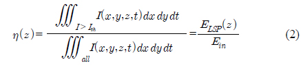
The square beam homogenizer should generate a maximum square image size D=0.26 cm in order to peen Alloy 22, which has the 10 GW/cm2 of Ith [1] with the incident beam. Figure 2(b) shows the LSP region among the irradiated input beam region. The beam distributions at positions −0.4, −0.3, −0.2, 0.0, 0.2, and 0.4 cm from the target are shown in Figure 2(c). The white zone indicates the area over the plasma threshold. With the given beam distributions near the target, the efficiency is obtained by considering the Ith as one of the properties of the square uniform beam for the LSP. The efficiency is the ratio of the energy (ELSP) in the plasma area to the input energy (Ein) on the target. The efficiency is defined as
where I(x, y, z, t) is the intensity distribution near the target and the temporal shape of the input pulse was supposed to be rectangular.
Figure 2(c) also shows the energy efficiency near the target. The maximum point of the energy efficiency graph (ηM) is not located on the target position but −0.23 cm away from the target. We set the minimum energy efficiency as 0.5 similar to FWHM in order to define the LSP-DOF from this graph which has arbitrary shape. According to this definition, the LSP-DOF is 0.7 cm.
Metal has a specific plasma thresholds intensity (Ith). The number of lenslets (NAL) in the array-lens is related to the uniformity of the square beam [12, 13]. The focal length (fC) of the condenser lens and the input beam size (Din) are the parameters in a conventional DOF. For these reasons, we selected these four main parameters in order to find the relationship with the LSP-DOF.
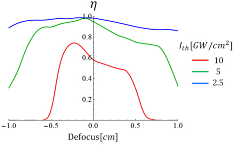
In the first simulation, the different Ith of three types of metals were applied to the beam distributions previously determined in the preliminary simulation (Table 1.). The three types of metals are Alloy 22, Ti-6AL-4V, and 316 L SS, and these Ith are 10, 5, and 2.5 GW/cm2, respectively [1]. When the square uniform beam (D=0.26 cm) is radiated at different metals, the efficiency is shown in Fig. 3.
Figure 3 shows the efficiency near the target for the Ith. When the Ith are 10, 5, and 2.5 GW/cm2, positions of the ηM are −0.23, −0.10 and −0.12 cm from the target, respectively; the LSP-DOF are 0.7, 1.8, and 5.6 cm respectively. As the Ith decreases, the position of the ηM approaches the target plane. This, in turn, causes an increase in the efficiency and elongates the LSP-DOF. The overall efficiency level ascends when Ith descends. However, for a low Ith, it is not always optimal to peen the target with a small square beam size. If the efficiency fulfills the minimum required value in the LSP industrial field, the square image size on the target can be increased in order to peen the target efficiently.
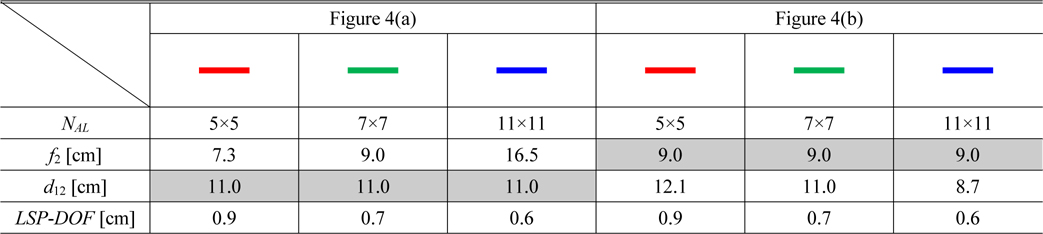
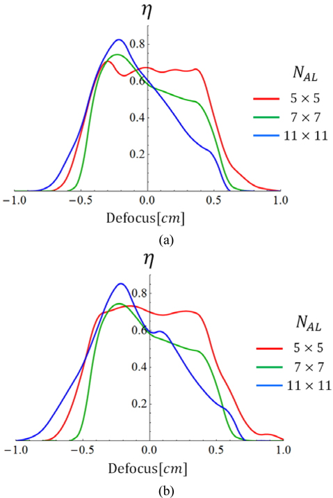
he second simulation was to change the number of lenslets in the array-lens (NAL) and it was performed twice differently according to each parameter, f2 and d12. When the NAL is equal to 5×5, 7×7, and 11×11, f2 is changed along with the NAL in the first case and the d12 is changed along with the NAL in the second case. The other parameters are the same as parameters of the preliminary simulation except for the NAL, f2 and d12 for D=0.26 cm. Table 2 lists values of main parameter NAL, two dependent parameters f2, d12 and LSP-DOF about the two cases.
In the first case (Fig. 4(a)), when the NAL is equal to 5×5, 7×7, and 11×11 the positions of the ηM are −0.30, −0.23 and −0.21 cm respectively; the LSP-DOF is 0.9, 0.7, and 0.6 cm respectively. In the second case (Fig. 4(b)), when the NAL is equal to 5×5, 7×7, and 11×11 the positions of the ηM are −0.33, −0.23 and −0.22 cm respectively; the LSP-DOF values are 0.9, 0.7, and 0.6 cm respectively. There is a similarity between the two cases as shown in Fig. 4(a) and (b). It means that the adjustment of interval (d12) is more convenient than the changing of the lens (f2). It is known that the uniformity of the square beam at the target plane becomes better when the NAL rises [12, 13], but the LSP-DOF shortens in all the cases. There is a trade-off between the beam uniformity and the LSP-DOF. When the NAL is increased, the maximum point of the energy efficiency is also increased and the slope of the energy efficiency graph becomes steeper.
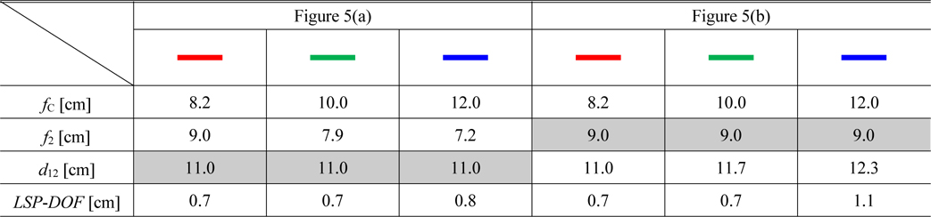
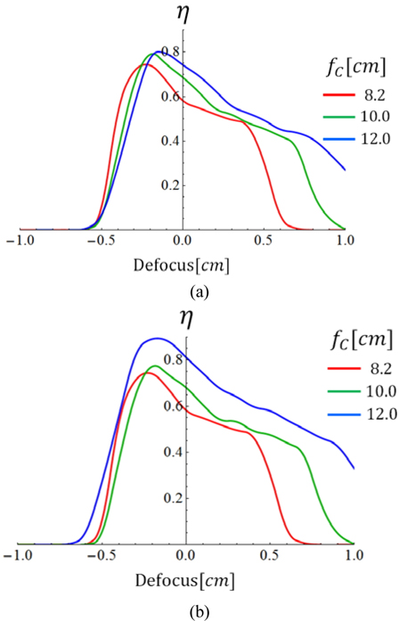
The purpose of the third simulation was to change the focal length of the condenser lens (fC) and it was carried out two times differently according to each parameter, f2 and d12. When the fC values are 8.2, 10.0, and 12.0 cm, f2 is changed along with fC in the first case and d12 is changed along with fC in the second case. The other parameters are the same as parameters of the preliminary simulation except for the fC, f2 and d12 for D=0.26 cm. Table 3 lists values of main parameter fC two dependent parameters f2, d12 and LSP-DOF about the two cases.
In the first case (Fig. 5(a)), when the fC values are 8.2, 10.0, and 12.0 cm the positions of the ηM are −0.23, −0.19, and −0.13 cm, respectively; the LSP-DOF values are 0.7, 0.7, and 0.8 cm, respectively. In the second case (Fig. 5(b)), when the fC values are 8.2, 10.0, and 12.0 cm the positions of the ηM are −0.23, −0.17, and −0.11 cm, respectively; the LSP-DOF values are 0.7, 0.7, and 1.1 cm, respectively. There are slight differences between the two cases about the positions of the ηM. The LSP-DOF in the second case is longer than the result of the first case. In this simulation, adjusting the interval (d12) is not only convenient but also advantageous to the LSP-DOF. When the fC values increase, the LSP-DOF becomes longer and the ηM shifts to the right owing to the influence of the spherical aberration. We need to analyze input beam size additionally to understand the spherical aberration and the LSP-DOF.
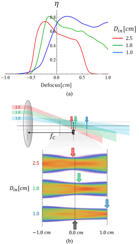
In the fourth simulation, the input beam size (Din) was changed. The parameters of the square beam homogenizer were equal to the conditions in the preliminary simulation except for the Din. Figure 6(a) shows the efficiency for the three cases of the changes in Din.
When the Din values are 2.5, 1.8 and 1.0 cm, the positions of the ηM are −0.23, −0.13, and 0.23, respectively; the LSP-DOF values are 0.7, 1.0, and 2.6 cm respectively. When the Din is smaller, the position of the ηM passes through the target plane and the LSP-DOF becomes longer. Figure 6(b) shows the concept of the changing beam waist; when the different height of the incident beamlets is going to the condenser lens. Because the influence of the spherical aberration is diminished when the Din is small, the slope of the irradiated input beam is gentle and the position of the beam waist shifts to the right. The small Din is related to long conventional DOF. However, small Din is not always a good condition for the LSP. When the Din is small, the number of beamlets that pass through the array-lens is small as well. Decreasing of the number of beamlets will diminish the uniformity of the square beam at the target plane [12, 13]. Research about the uniformity of the square beam needs to be studied as further work.
We have designed a multi-aperture square beam homogenizer to reform the shape and distribution of the input beam simultaneously. The LSP-DOF was defined with the efficiency near the target. A long LSP-DOF is required, as it is important to have a long WD in application field of the LSP. When the square beam homogenizer was applied to the LSP, we found that low Ith, small NAL, long fC and small Din were advantageous in obtaining an elongated LSP-DOF. The f2 and d12 were selected as the dependent parameters. Modifying d12 is convenient and beneficial to obtain long LSP-DOF more than varying f2 when fC is the main parameter. In addition, we have calculated and analyzed the maximum efficiency position of the LSP according to change the four parameters. Understanding these characteristics is useful to design a square beam homogenizer for the LSP. Further work in this subject would involve an analysis of the uniformity of the beam and its effect on the peening quality