검색 전체 메뉴
PDF
맨 위로
OA 학술지
Transformation Optics Methodology for Changing the Appearance of an Object
  • 비영리 CC BY-NC
  • 비영리 CC BY-NC
ABSTRACT
Transformation Optics Methodology for Changing the Appearance of an Object
KEYWORD
Transformation optics , Coordination transformation , Anisotropic media , Metamaterial
  • I. INTRODUCTION

    Since transformation optics was proposed by J. B. Pendry in 2006 [1, 2], it has attracted enormous interest in exploring various devices. In the past few years, transformation optics has been proved to be a powerful technique to arbitrarily control electromagnetic fields. The basic idea of transformation optics is that the Maxwell equations remain forminvariant under coordinate transformations. The result of a certain transformation is a direct link between the permittivity and permeability of the material in different coordinate systems. And the metric tensors of the transformed space that contains the desired electromagnetic properties can also be derived simultaneously [3-5]. Transformation optics has become a fundamental tool for exploring a diverse set of devices with novel properties, such as cloaks [6, 7], concentrators [8], lenses [9-12], waveguide bends and transitions [13-17], antennas [18-26], and so on. Generally speaking, the generated materials are inhomogeneous and anisotropic by transformation optics methodology. We can use metamaterial to fabricate the devices. Metamaterial is an artificial material with properties that may not be found in nature, and it gains its properties not from their composition but from their exactingly-designed structures.

    In this paper, the transformation optics concept is applied to change the apparent size of a cross section. In order to make the appearance of an object is equivalent to a larger or smaller one, the appropriate transformation function needs to be employed. At the same time, the proper material’s parameters can be gained and the impedances at the inner and the outer boundaries of the device are matched. The results are validated by numerical simulations by using different cross sections.

    II. TRANSFORMATION FORMULATIONS

    In a space point of view, the transformation optics technology consists in compressing or expanding a certain space into another region. Firstly, to achieve the aim that the appearance of an object is transformed into a much larger or smaller one, the space around the object is discretized into two different zones. The inner space which is delimited by radius a is compressed or expanded into a space delimited by radius c, and this can be realized by a linear transformation. Through the operation, the first zone will make an object appear bigger or smaller than its real physical size. The second zone ensures the impedance at outer boundaries matching with the surrounding radiation environment. The operating principle is shown in Fig. 1(a). In the transfor-mation, the space is described by cylindrical coordinates and the angular part of these coordinates remains unchanged. The region with radius c and b constitutes an impedance matching space. This space transformation can also be performed using a linear transform. Figure 1(b) shows a coordinate transformation from a virtual space (r) to a physical space (r'). In Fig. 1(b) it is noted that the transformation r’ = f(r) is a continuous function from r = 0 to r = b, which ensures that the impedance is matched at all values for r and thus the system is without any reflection.

    The transformation formulas in the two regions can be mathematically expressed as follows

    image

    and

    image

    where α = c / a, β = (b-a) / (b-c). Here the physical meaning of the factor α is the compression factor applied in the central region. This factor has a transition value 1. If α > 1, it indicates that the region 0 < r < a in the initial space is expanded, otherwise the region is compressed.

    To physically design the proposed device, the permittivity and permeability components in the transformed space have to be expressed in the Cartesian coordinate system. Since the functions are described in cylindrical coordinate systems in original space, the matrix relations between cylindrical and Cartesian coordinates are used.

    The Jacobean matrix representing the relations between different coordination systems is defined as

    image

    If the original space is vacuum, the coefficient of the material can be written as

    image

    Taking Equation (1) to Eqs. (3) and (4), the relative permittivity and the relative permeability tensors of the materials in the transformed regions can be obtained. They are expressed as

    image

    and

    image
    image

    where . These parameters are relatively simple for the transformation in the inner zone since it leads to constant values.

    III. RESULTS AND DISCUSSIONS

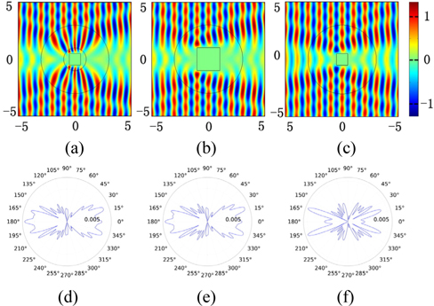
    Here a quadrate cross section is taken for example and a finite-element method is used to perform simulations of the transformation presented above. The validation of the design is performed in a two-dimensional configuration and a z-polarized TE wave (parallel to the z-axis) is incident. The frequency of the incident wave is set at 3 GHz.

    With all the material parameters above, the functionality of the device is examined. In order to verify the conclusion, the calculation with the compression factor of α = 1/2 is performed and the results are shown in Fig. 2. Here, it is fixed that a = 0.2 m, b = 0.3 m and the cross section is supposed to have an edge length d = 0.1 m. In this scenario, a scattering pattern similar to a smaller cross section in the metamaterial shell is observed, demonstrating that the small size cross section inserted in the proposed material shell presents the same electromagnetic behavior as a much bigger cross section in free space. Figure 2(a) shows the scattering pattern of the original cross section being located in the shell. Figure 2(b) shows the corresponding scattering pattern of a new cross section which has been increased by a factor of 1 / α in size. Outside the region r = b, the functionalities of both cross sections are almost the same. The scattering pattern of the original cross section is shown in Fig. 2(c), which is obviously different from those in Figs. 2(a) and 2(b). Thus the apparent size of the cross section may be increased. The same conclusion can be drawn from the far-field distributions presented in Figs. 2(e)~(g).

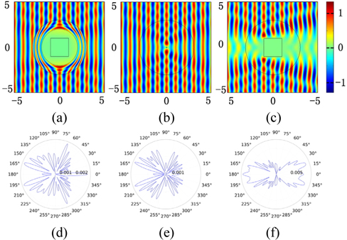
    Furthermore, if the inner region in the original space is expanded, the opposite conclusion can be drawn. To verify the design mentioned, the geometry structure parameters are set to be a = 0.1 m and b = 0.3 m. Figure 3(a) shows the scattering electric field distribution of a quadrate cross section in a metamaterial shell having a compression factor α = 2. The cross section is supposed to have an edge length d = 0.2 m. Figure 3(b) shows that a cross section with a much smaller size d = 0.1 m is embedded in free space. The scattering of the original cross section in free space is illustrated in Fig. 3(c). Therefore, It can be found that a larger object in the metamaterial shell has the same functionality as the 1 / α times smaller cross section in free space. In other words, the physical appearance of an object embedded in the metamaterial shell can be changed 1 / α times.

    In order to further verify the performance of the proposed device, the scattering pattern of a cross section with b = 0.3 m, a = 0.01 m and α = 20 is plotted in Fig. 4. It is observed that the scattering of a cross section is decreased greatly by being inserted in the metamaterial shell. It can be imagined that if α →∞, the scattering electric field distribution of an object is equivalent to that of a smaller cross section, which can be infinitesimal.Then the proposed material shell will be a cloak. Because α is not small enough in this paper, there exist some differences between Figs. 4(e) and 4(f). The larger α is, the more similar Fig. 4(e) is to Fig. 4(f).

    Overall, the above results show that the apparent size of a cross section is indeed changed by expanding or compressing the space around the cross section. Therefore, it can be concluded that the method of transformation optics can generate the performance to change the apparent size of an object.

    IV. CONCLUSION

    In summary, transformation optics methodology is based on the form invariance of Maxwell’s equations under coordinate transformations, and it provides an extremely versatile set of design tools by employing special-coordinate transformations, where the compression or dilation of space in different coordinate directions is interpreted as appropriate scaling of the parameters. The appearance of an object can be changed with the transformation electromagnetics methodology.

    The important step of the methodology in this paper is determining what transformation functions will be applied to obtain the permittivity and permeability tensors of the device. In the concept mentioned in this paper, two linear transformations are used and an artificial shell is designed which makes the appearance of the cross section bigger or smaller. As we all know, the initial and most well-known application of the transformation optics methodology is the invisibility cloak, and the device designed in this paper will be an invisibility cloak in a limited case. Numerical simulations have been shown to confirm the operating principle of the transformations and the performance of the cloak. It shows further that the methodology proposed here can be applied to change the scattering of an object in both microwave and optical regimes and to design a cloak.

참고문헌
  • 1. Leonhardt U. (2006) “Optical conformal mapping,” [Science] Vol.312 P.1777-1780 google cross ref
  • 2. Pendry J. B., Schurig D., Smith D. R. (2006) “Controlling electromagnetic fields,” [Science] Vol.312 P.1780-1782 google cross ref
  • 3. Crudo R. A., O’Brien J. G. (2009) “Metric approach to transfor­mation optics,” [hys. Rev. A] Vol.80 P.033824 google
  • 4. Leonhardt U., Philbin T. G. (2006) “General relativity in electrical engineering,” [New J. Phys.] Vol.8 P.247 google cross ref
  • 5. Leonhardt U., Philbin T. G. (2009) “Transformation optics and the geometry of light,” [Prog. Opt.] Vol.53 P.69-152 google
  • 6. Schurig D., Mock J., Justice B., Cummer S., Pendry J., Starr A., Smith D. R. (2006) “Metamaterial electromagnetic cloak at microwave frequencies,” [Science] Vol.314 P.977-980 google cross ref
  • 7. Zolla F., Guenneau S., Nicolet A., Pendry J. (2007) “Electro­magnetic analysis of cylindrical invisibility cloaks and the mirage effect,” [Opt. Lett.] Vol.32 P.1069-1071 google cross ref
  • 8. Rahm M., Schurig D., Roberts D., A., Cummer S. A., Smith D. R., Pendry J. B. (2008) “Design of electromagnetic cloaks and concentrators using form-invarian coordinate transfor­mations of Maxwell’s equations,” [Photon. Nano. Fund. Appl.] Vol.6 P.87-95 google cross ref
  • 9. Kundtz N., Smith D. R. (2010) “Extreme-angle broadband meta­material lens,” [Nat. Mater.] Vol.9 P.129-132 google cross ref
  • 10. Kwon D. H., Werner D. H. (2008) “Transformation optics designs for wave collimators, flat lenses and right-angle bends,” [New J. Phys.] Vol.10 P.115023 google cross ref
  • 11. Roberts D., Kundtz N., Smith D. (2009) “Optical lens com­pression via transformation optics,” [Opt. Express] Vol.17 P.16535-16542 google cross ref
  • 12. Tsang M., Psaltis D. (2008) “Magnifying perfect lens and superlens design by coordinate transformation,” [Phys. Rev. B] Vol.77 P.035122 google cross ref
  • 13. Huangfu J., Xi S., Kong F., Zhang J., Chen H., Wang D., Wu B. I., Ran L., Kong J. A. (2008) “Application of coordinate transformation in bend waveguide,” [J. Appl. Phys.] Vol.104 P.014502 google cross ref
  • 14. Nicolet A., Zolla F., Guenneau S. (2004) “A finite element modelling for twisted electromagnetic waveguides,” [Eur. Phys. J. Appl. Phys.] Vol.289 P.153-157 google
  • 15. Rahm M., Cummer S., A., Schurig D., Pendry J., B., Smith D. R. (2008) “Optical design of reflectionless complex media by finite embedded coordinate transformations,” [Phys. Rev. Lett.] Vol.100 P.063903 google cross ref
  • 16. Rahm M., Roberts D., Pendry J., Smith D. (2008) “Transfor­mation-optics design of adaptive beam bends and beam expanders,” [Opt. Express] Vol.16 P.11555-11567 google cross ref
  • 17. Tichit P. H., Buroku S. N., de Lustra A. (2010) “Waveguide taper engineering using coordinate transformation technology,” [Opt. Express] Vol.18 P.767-772 google cross ref
  • 18. Allen J., Kundtz N., Roberts D. A., Cummer S. A., Smith D. R. (2009) “Electromagnetic source transformations using superellipse equations,” [Appl. Phys. Lett.] Vol.94 P.194101 google cross ref
  • 19. Jiang Z. H., Gregory M. D., H. Werner D. (2011) “Experi­mental demonstration of a broadband transformation optics lens for highly directive multibeam emission,” [Phys. Rev. B] Vol.84 P.165111 google cross ref
  • 20. Lu W., Lin Z., Chen H., Chan C. (2009) “Transformation media based super focusing antenna,” [J. Phys. D] Vol.42 P.212002 google cross ref
  • 21. Luo Y., Zhang J., Ran L. X., Chen H., Kong J. A. (2008) “Controlling the emission of electromagnetic source,” [PIERS Online] Vol.4 P.795-800 google cross ref
  • 22. Popa B. I., Allen J., Cummer S. A. (2009) “Conformal array design with transformation electromagnetics,” [Appl. Phys. Lett.] Vol.94 P.244102 google cross ref
  • 23. Tichit P. H., Burokur S., Germain D., de Lustrac A. (2011) “Design and experimental demonstration of a high-directive emission with transformation optics,” [Phys. Rev. B] Vol.83 P.155108 google cross ref
  • 24. Tichit P. H., Burokur S., Germain D., de Lustrac A. (2011) “Coordinate transformation based ultra-directive emission,” [Electron. Lett.] Vol.47 P.580-582 google cross ref
  • 25. Tichit P. H., Burokur S. N., de Lustrac A. (2011) “Transfor­mation media producing quasi-perfect isotripic emission,” [Opt. Express] Vol.19 P.20551-20556 google cross ref
  • 26. Tichit P. H., Burokur S. N., de Lustrac A. (2013) “Reducing physical appearance of electromagnetic sources,” [Opt. Express] Vol.21 P.5053-5062 google cross ref
이미지 / 테이블
  • [ FIG. 1. ]  Representation of the proposed coordinate transformation: (a) the operating principle of the coordination transformation, (b) the transformation functions.
    Representation of the proposed coordinate transformation: (a) the operating principle of the coordination transformation, (b) the transformation functions.
  • [ ] 
  • [ ] 
  • [ ] 
  • [ ] 
  • [ ] 
  • [ ] 
  • [ ] 
  • [ FIG. 2. ]  (a) A quadrate cross section with side length d = 0.1 m in a metamaterial shell, (b) a quadrate cross section with side length d = 0.2 m in free space, (c) a quadrate cross section with side length d = 0.1 m in free space, (e) (f) and (g) are far-field distributions of (a) (b) and (c) respectively.
    (a) A quadrate cross section with side length d = 0.1 m in a metamaterial shell, (b) a quadrate cross section with side length d = 0.2 m in free space, (c) a quadrate cross section with side length d = 0.1 m in free space, (e) (f) and (g) are far-field distributions of (a) (b) and (c) respectively.
  • [ FIG. 3. ]  (a) A quadrate cross section with side length d = 0.2 m in a metamaterial shell, (b) a quadrate cross section with side length d = 0.1 m in free space, (c) a quadrate cross section with side length d = 0.2 m in free space, (e) (f) and (g) are far-field distributions of (a) (b) and (c) respectively.
    (a) A quadrate cross section with side length d = 0.2 m in a metamaterial shell, (b) a quadrate cross section with side length d = 0.1 m in free space, (c) a quadrate cross section with side length d = 0.2 m in free space, (e) (f) and (g) are far-field distributions of (a) (b) and (c) respectively.
  • [ FIG. 4. ]  (a) A quadrate cross section with side length d = 0.2 m and α = 20 in a metamaterial shell, (b) a quadrate cross section with side length d = 0.01 m in free space, (c) a quadrate cross section with side length d = 0.2 m in free space, (e) (f) and (g) are far-field distributions of (a) (b) and (c) respectively.
    (a) A quadrate cross section with side length d = 0.2 m and α = 20 in a metamaterial shell, (b) a quadrate cross section with side length d = 0.01 m in free space, (c) a quadrate cross section with side length d = 0.2 m in free space, (e) (f) and (g) are far-field distributions of (a) (b) and (c) respectively.
(우)06579 서울시 서초구 반포대로 201(반포동)
Tel. 02-537-6389 | Fax. 02-590-0571 | 문의 : oak2014@korea.kr
Copyright(c) National Library of Korea. All rights reserved.