According to recent trends of flexible and large size displays, developments of flexible transparent electrode films that can be formed at flexible substrates such as PET, PES, and PEN are required. Also, display related parts markets are rapidly expanding according to the dramatic growth in mobile display industries including smart phones and notebook computers. In the case of functional films, there have been many efforts in applying mechanically, electrically, optically, and thermally excellent functional films to products through convergence and integration technologies.
A surface emission gradient minimization (Honey Comb) technology allows fast processing of grid pattern grooves with different thicknesses and widths in a side of films through an imprinting process. Also, the process utilizes support rollers at the lower section in a coater and that shows more precise performance in the printing process. For applying this imprinting technology to transparent electrode films, low sheet resistance, high adhesive strength, and high light transmittance and is necessary to remove wrinkles presented in a printing section in films. In addition, mass production issues are addressed by reducing processing times and costs caused by damage to films. This study represents performances in developing transparent electrode films that satisfy these characteristics.
2. DESIGN OF A ROLL-TO-ROLL NANO MICRO COATING SYSTEM
Figure1 shows an optimal 3D model for the entire coating system with UNWINDER and REWINDER UNITS, IN-FEED and OUT-FEED UNITS, IMPRINTING UNIT, REMOLDING UNIT, INKING UNIT, CLEANING UNIT, BAR Coating UNIT, and DRYER UNIT.
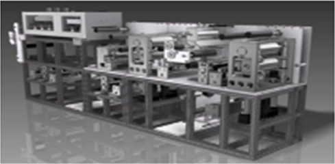
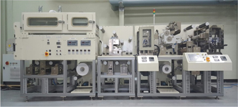
Figure 2 shows a practical nano micro coating system based on the 3D model presented in Fig. 1. In fabricating blue light cut films that show proper hardness, the features of this system are designed by low friction bearings and related appliances in order to implement anti-vibration mechanism design control and support feedback control using position sensors, load cells, and EPC for controlling precise tensions and maintaining angles of rolls and webs.
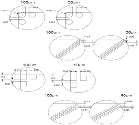
Figure 3 represents fabricated patterns in which the optimal design of the system is very important because the coating thickness is governed by the shape, line width, angle, and roll diameter of mesh types.
The experiment performed in this study fabricated and evaluated films with low sheet resistance, high adhesive strength, and high light transmittance using the roll-to-roll nano micro coating system based on the design in Fig. 1 and Fig. 2.
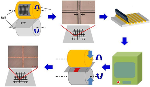
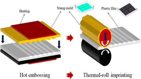
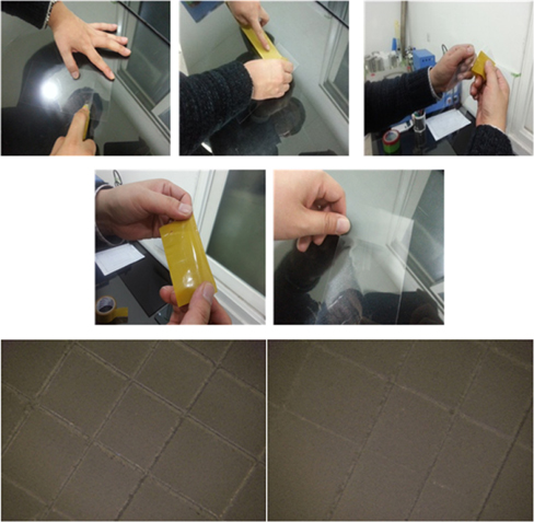
The experiment was performed as follows. The imprinting process was processed at 100℃ with a pressure and feeding rate of 200 kgf/㎠ and 1mm/sec respectively. Also, the remolding process was performed at 120℃ with a pressure and feeding rate of 300 kgf/㎠ and 1mm/sec respectively. Figure 4 illustrates the imprinting system process.
Figure 5 shows the imprinting process performed in this system. The substrate used in this process is a PET Film (plastic temperature: 150℃, light transmittance: >89.5%, and thickness: 100 ㎛). The TEST was performed using Ag paste conductive nano ink (Ag content: 40%, specific resistance: 3~5 Ω/㎝). The first step is the imprinting process by applying the PET film to the Honey Comb Pattern roll.
The second step is charging the conductive nano ink (Ag paste) to the molded pattern performed by the imprinting process using a doctoring method with doctor blades. Then, the remained ink around the pattern was removed by a contact roll cleaning method using roll papers. The last step is fabricating transparent electrode films through a drying process at a condition of 140℃/5 min.
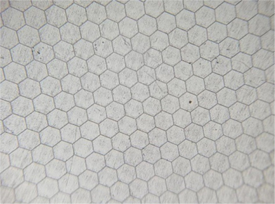
Figure 6 shows the molded pattern in the IMPRINTING Roll in which the Honey Comb Pattern is fabricated using the optimal design because the coating thickness is determined by the shape, line width, angle, and roll diameter of patterns.
In this study transparent electrode films were fabricated using the surface emission gradient minimization (Honey Comb) technology in order to perform high light transmittance and low sheet resistance and the films were analyzed as follows.
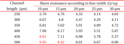
The light transmittance and sheet resistance can be controlled by changing line widths and intervals. The sheet resistances measured by varying the line widths and intervals are presented in Table 1.
[Table 1.] Changes in the sheet resistance according to line widths and intervals.

Changes in the sheet resistance according to line widths and intervals.
In general, the sheet resistances were measured by less than 10 Ω/□ and that shows a possibility of applying it as high level transparent electrodes.
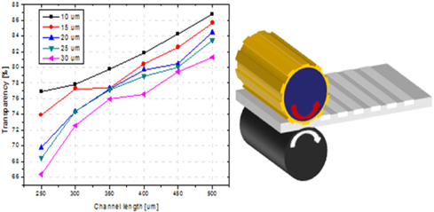
Figure 7 represents the results of the nano micro coating and the results show excellent transmittance more than 91% as shown in Table 2. In addition, an adhesive strength test was implemented to verify the coating as shown in Fig. 8.
[Table 2.] Film transmittances for line widths and intervals.
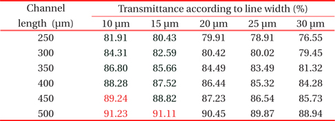
Film transmittances for line widths and intervals.
In this study, films for IT applications with a transmittance of more than 90%, a sheet resistance of less than 10 Ω/□, and an adhesive strength of more than 100% were developed. Also, both blading methods fill the patterns with Ag paste and the paste is filled to the inside of the patterns. In results, the Ag paste was nicely filled into the patterns and forms silver electrodes after applying a drying process. The particles of the Ag paste should be determined at a nano scale instead of a micro scale because the micro scaled particles show severe lumping and that represents a difficulty in the conduction between particles.
A next generation transparent electrode that may replace ITO technology was developed by low resistance and conductive polymers. The imbalance in surface resistance was solved by forming thin films using conductive polymer and allows fabricating transparent electrodes with a sheet resistance of less than 10 Ω/□ and a light transmittance of more than 90%. In addition, the fabrication of films appeared to reduce the number of processes compared to the conventional method and is easily performed at room temperature without using vacuum and deposition processes. The results of this study reaches the level of advanced countries up to 90% and the localization rate also reaches up to 80%. Although this technology may increase the commercial values of flexible display films, its transmittance and sheet resistance must be improved according to requirements of flexible display industries.