For visual measurement under dynamic scenarios, a zoom lens camera is more flexible than a fixed one. However, the challenges of distortion prediction within the whole focal range limit the widespread application of zoom lens cameras greatly. Thus, a novel sequential distortion correction method for a zoom lens camera is proposed in this study. In this paper, a distortion assessment method without coupling effect is depicted by an elaborated chessboard pattern. Then, the appropriate distortion correction model for a zoom lens camera is derived from the comparisons of some existing models and methods. To gain a rectified image at any zoom settings, a global distortion correction modeling method is developed with bundle adjustment. Based on some selected zoom settings, the optimized quadratic functions of distortion parameters are obtained from the global perspective. Using the proposed method, we can rectify all images from the calibrated zoom lens camera. Experimental results of different zoom lens cameras validate the feasibility and effectiveness of the proposed method.
The precision of photogrammetry and 3D stereovision application is intimately related to the accuracy of the camera calibration, especially related to the camera distortion correction. An imprecise distortion model would degrade the accuracy of 3D scene reconstruction and remote sensing directly. At some changing scenarios with different field of views, such as video monitoring, dynamic measurement and so on, the zoom lens cameras capable of adapting their focal lengths, are chosen for their better performances over fixed focal cameras. But due to the complex structure of the zoom lens, the distortion conditions of zoom lens cameras are unpredictable, which would severely hurt image registration, reconstruction or measurement. Therefore, building ideal distortion models and conveniently correcting distortion for zoom lens cameras gains more attention.
Most distortion correction methods for current zoom lens cameras are based on a series of mono-focal cameras, and they provide some guidance for distortion correction of zoom lens cameras to some extent. To date, there has been tremendous progress in mono-focal distortion correction. [1-3] proposed distortion correction methods with calibration targets. They are widely used for their flexibility and accuracy. To reduce the dependence on the metric calibration target, some pattern-free distortion correction methods were proposed. Epipolar lines [4], straight lines [5] across the captured image, were applied to estimate the distortion parameters. Other methods [6-8] estimated and corrected the radial distortion by minimizing an algebraic error. These methods had mainly focused on solving lens distortion correction with radial distortion model, and the accuracy of pattern-free distortion correction methods tend to be unstable.
Given the distortion correction of the zoom lens camera, the most challenging issue is that distortion parameters vary with changing zoom settings. To perform the rectification of any image from the zoom lens camera, distortion parameters covering the entire zoom setting must be known in advance. Calibrating a zoom lens camera on all its possible focal lengths, however, is impractical as it is enormously time-consuming. Therefore, modeling the distortion parameters of a zoom lens camera easily and effectively is meaningful work, and some researchers have made great contributions to the relevant work.
Zoom lens cameras calibration had been implemented at [9], they mainly focused on the intrinsic and extrinsic parameter acquirement and neglected the distortion. The distortion parameters, accompanied with the intrinsic and extrinsic parameters of the zoom lens camera, were estimated simultaneously [10-12], however, these methods may result in a coupling effect between distortion parameters and other calibrated parameters. The method [13], computing lens distortion separately from the pin-hole model with planar template images, addressed the calibration instabilities and the coupling problem. [14, 15] expressed the interior orientation and lens distortion as a function of focal length, but the global optimized solutions of distortion correction for the zoom lens camera were not considered. Apart from the above research, some existing software [16-18] can be used to correct zoom lens distortion.
These aforementioned methods can rectify the distortion of zoom lens cameras effectively, however, due to the complex structure of changeable zoom lenses, the distortion correction based on the radial distortion model may be not precise enough. Furthermore, for the proposed polynomial methods above, the distortion coefficients obtained at different focal lengths are independent of each other, thus they cannot represent the global optimization covering all zoom settings. Therefore, a distortion model with radial and tangential parts is used in this paper, and the global optimization for the distortion parameters modeling of zoom lens cameras with bundle adjustment is proposed.
The remainder of the paper is organized as follows: Section 2 describes the camera imaging theory and the distortion correction models. Section 3 illustrates different distortion assessment methods with an elaborate chessboard as a ground truth, and then the suitable distortion correction model is selected for a zoom lens camera by comparison. Section 4 carries out the bundle adjustment of distortion coefficients corresponding to different focal lengths within a zoom range, followed by the polynomial method with the overall optimization distortion parameters. Section 5 presents the experimental results conducted from the zoom lens camera distortion correction, which confirm the effectiveness and accuracy of the proposed method. And finally, concluding remarks are summarized.
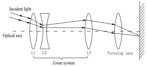
The distortion of a camera objectively exists in every image regardless of the quality of the camera and lens. Given a complex, multi component lens for gathering and focusing incoming light, zoom lens cameras are much more complicated than pinhole cameras. The distortion issues occur more severely due to the complex zoom lens structure in the zoom lens cameras, which may lead to more damage to the image quality.
In order to ease the distortion degradation, a variety of lens distortion models are established corresponding to different lens types and application fields [19]. But it is still a difficult task to choose a suitable distortion model with the tradeoff between the accuracy and efficiency. Usually, the camera distortion models can be grouped into radial distortion model and global distortion model (containing radial and tangential distortion), a brief description of the above two models are presented as follows.
As known to us, the widely used radial distortion model [5] is given by the following Eq. (1) :

Where (

The complexity of the model is given by the number of terms of the Taylor expansion in
One important consequence of distortion is that the projections of 3D straight lines in the image are curves (no longer straight lines). Therefore, correcting the curves into straight lines is an obvious method for distortion correction. Without loss of generality, a widely used planar chessboard pattern with

Substituting Eqs. (1) and (2) to Eq. (3), and the only unknown parameters in
Generally speaking, radial distortion is caused by flaws in the radial curvature of the lens elements, and tangential distortion is caused by the non-collinearity of the optical centers of the lens elements. Radial distortion usually dominates the distortion condition in a high quality lens or wide-angle lens. Therefore, it may be enough for distortion correction with a radial model only in some cases for a fixed lens.
But due to the interchangeable zoom lenses of zoom lens cameras, the position relationship caused by the continuous change between lens and camera cannot be predicted regularly, which would increase non-collinearity of the optical centers and leads directly to tangential distortion. As shown in Fig. 1, the principal point should meet with the center of the image plane when lens elements are aligned perfectly along the axial direction. However, it may stray from the exact image center due to the complexity of the lens assembly and the integration of gears or servos for lens movement.
Therefore, the global distortion model is established by adding a tangential component to the radial distortion as Eq. (4).

Where is the ideal 2D image point without distortion, (

If

Where A is a 2

3.1. Evaluation for Distortion Estimation
To evaluate the distortion correction results from different distortion models objectively, many assessment methods are proposed by related scholars. Re-projection error [20] and pattern photograph matching [21], had been used to evaluate the distortion correction results, they may lead to coupling errors or were time-consuming. And the highly precise “calibration harp” [22], however, is sensitive to the calibration circumstance. In this paper, an elaborate calibration chessboard pattern is chosen as a ground truth, and the evaluation method is performed with the sub-pixel corners extraction in the image. Based on the principle that a straight line in 3D would project to a straight line in 2D planar, straightness deviation in the planar image is defined as the distortion correction evaluation. Taking into account the straight lines in the vertical and horizontal directions on a chessboard pattern, and the RMSs (Root Mean Square) from a set of distorted corners to the specific physical line are defined as the straightness error. This method can also avoid the coupling problem between the distortion condition and the calibrated parameters.
As described in Section 2.1, given the chessboard pattern with
With

Since (

Thus, the RMS (Root mean square)

Where
3.2. Method Selection for Zoom Lens Distortion Correction
With the assessment criteria described in Section 3.1, the RMS
1. PTlens: Commercial software to automate distortion correction, which is widely used in zoom lens cameras. It can correct lens pincushion/barrel distortion, vignetting, chromatic aberration, and perspective. 2. GIMP:GIMP is an acronym for GNU Image Manipulation Program. According to the lens model and focal length embedded in the EXIF (Exchangeable Image File), the distortion coefficients can be obtained from the Lensfun library for zoom lens distortion correction. 3. Hugin: An open source panorama stitcher and graphical user interface for panorama tools. It provides a number of additional components and command line tools. The software is used to calibrate the distortion coefficients of the lens from the image with some linear features across the image. 4. Global distortion modeling method: Both the radial and tangential distortion models are considered. The detailed model description is stated in Section 2.2.
The above four distortion correction methods are performed with the same chessboard planar (in Fig. 2), A 12 × 17 grid is engraved precisely on the alloy board. Each cell is 50 mm × 50 mm. It is obvious to notice that the top edge of the alloy board is bent due to image distortion. Therefore, rectification of the image distortion is important to reveal the real scene in photogrammetry and computer vision.
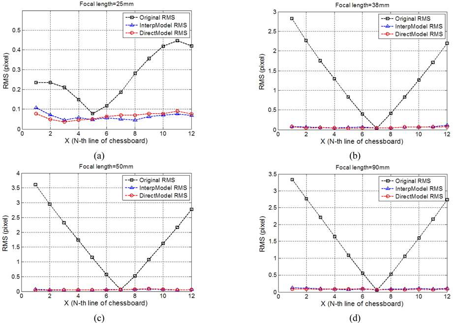
The Nikon D3100 camera with zoom lens Nikkor AF-S 18-55 mm is used to test different distortion correction models within an entire focal range. The RMSs of different distortion correction methods are depicted in Fig. 3. The consequences show that the RMS of the original image without distortion correction is at the maximum, with decreasing tendency from the image border to the image center. This phenomenon occurs in line with the law of distortion in the image. The aforementioned four undistorted methods can correct the image distortion by reducing the RMS to less than 1 pixel. It can be noticed easily that the distortion correction result of PTlens is not as good as GIMP and Hugin. The reason maybe that the distortion coefficient database of PTlens is less appropriate than GIMP for this zoom lens camera. According to the focal length from EXIF, the GIMP can find the corresponding distortion parameters in the lookup table. Hugin is based on the radial correction model by assuming the distortion center as the image center, and it needs certain linear features across the image to calibrate the distortion coefficients. In our experiments, the target chessboard pattern corners located in lines are selected as the control lines, and the distortion correction process is performed on the hypothesis that the selected distorted corners are located on the same straight line. Similar performances are shown on different focal lengths in Fig. 3 (a) to (d). It is easy to draw a conclusion that the global distortion correction model, which is indicated by red lines, can achieve the best distortion correction results. Therefore, the proposed global distortion correction model is employed for zoom lens calibration in the next Section.
IV. DISTORTION PARAMETERS MODELING
4.1. Bundle Adjustment for Zoom Lens Distortion Parameters
From Section 3, we know that the global distortion model has the least RMS in different focal lengths. Therefore, the global model is used to obtain the initial distortion parameters. A novel global optimization method for zoom lens camera distortion correction with bundle adjustment [23, 24] is proposed in this paper, which establishes the concept of global optimization for distortion correction of a zoom lens camera. Therefore, it provides a better alternative for zoom lens distortion correction.
To obtain the global distortion correction polynomial of a zoom lens camera,

In this paper, the chessboard corners in the 3D coordinate are seen as landmarks, which would generate the detected 2D corners in the image plane. The bundle adjustment is performed as a global optimization method by minimizing the total re-projection error of the observed chessboard corners at different lens settings, The method can be represented by the following non-linear least squares cost function (12).

Where
4.2. Distortion Parameters Modeling with Polynomial Approximation
The experiments are performed by Nikon D3100 camera with a NIKKOR AF-S 18-105mm lens. After the bundle adjustment, the zoom lens distortion coefficients
Table 1 shows the optimized distortion coefficient results after bundle adjustment at some focal lengths. Corresponding to the initial distortion parameter values, the total re-projection error is 1.35 pixels, which reduces dramatically to 0.33 pixels after bundle adjustment.
[TABLE 1.] Distortion parameters after bundle adjustment
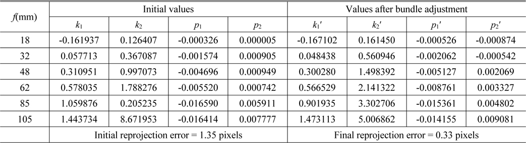
Distortion parameters after bundle adjustment
For a zoom lens camera, it is not practical to calibrate the zoom lens camera at all of its focal settings. With the bundle adjustment, an indirect method is established to estimate the distortion parameters of a zoom lens camera, which just needs to calibrate a distorted image at some certain focal lengths. Taking into account the accuracy and computing complexity, the quadratic functions of the distortion coefficients
A number of experiments have been conducted to verify the feasibility of the proposed distortion coefficients modeling method. The distortion coefficients, obtained from the above quadratic functions by substituting the focal length
Three different single lens reflex cameras fitted with different zoom lenses are applied in the experiments. The first camera is the Nikon D90 equipped with a Nikkor 18-105 mm f/3.5-5.6G ED VR lens.
(1) A series of chessboard planar images are captured at five different focal lengths (fEXIF = 18 mm, 32 mm, 62mm, 85mm, 105mm). To enhance the robustness of the fitted results, the selected focal length settings are supposed to cover the whole zoom range uniformly. (2) Given the distortion coefficients obtained at different focal lengths, the bundle adjustment algorithm is used to optimize the distortion polynomial function from the global viewpoint. The proposed distortion correction modeling method is used to obtain the quadratic function of distortion coefficients KdistF = {k1(f), k2(f), p1(f), p2(f)}. (3) With the random focal length fi read from EXIF, the corresponding distortion coefficients can be obtained easily according to the polynomial function. Then, these parameters can be used to correct the distorted image. (4) For example, after modeling of distortion coefficients, a chessboard pattern image shown in Fig. 5(a) is captured by the same camera. The distortion coefficients can be obtained by substituting the focal length f = 24 mm from EXIF to KdistF. Figs. 5(b) and (c) show the distortion correction results of the chessboard images with direct and interpolated distortion correction methods, respectively, and the sub-pixel corner locations with the above two distortion correction methods illustrate that the rectified results are close to each other, as shown in Fig. 5(d).
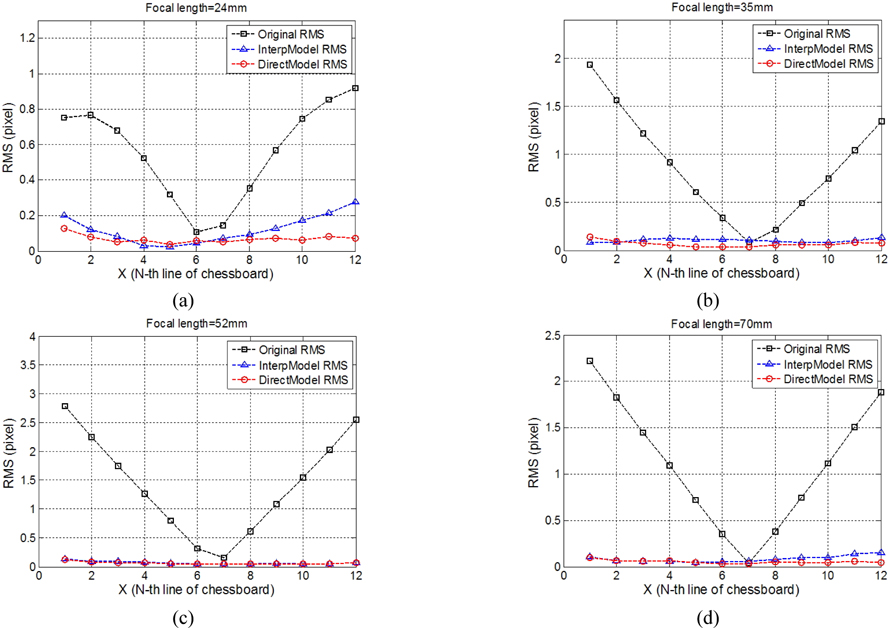
The RMSs of horizontal corner lines in a chessboard pattern at different focal settings are presented in Fig. 6. It is obviously noticed that the RMS of InterpModel (marked in blue) is very close to the DirectModel with ground truth (marked in red) at all the interpolated focal settings. Therefore, the distortion correction modeling method proposed in this paper is effective at correcting the zoom lens camera distortion. With this approach, the zoom lens distortion correction can be simplified into several mono-focal distortions corrections without loss of accuracy.
Another two cameras with different consumer grade classifications are tested to further validate the proposed method. In Fig. 7, the Nikon D750 camera with the AF-S Nikkor 24-70 mm f/2.8G ED lens is used, the RMS of the InterpModel and the DirectModel almost coincide with each other, which also demonstrates that the distortion coefficients modeling method can be used to represent the distortion condition of the zoom lens camera. The Nikon D3100 camera equipped with EF 18-105 mm zoom lens can validate the result more strongly, the comparison of results is shown in Fig. 8.
In this paper, a novel distortion correction modeling method for a zoom lens camera is presented. Given the coupling effect of distortion coefficients with intrinsic and extrinsic parameters, the re-projection error may be inappropriate to represent the undistorted result. Thus, a chessboard pattern is applied to assess the distortion correction with linear fitting characteristics. With the evaluation standard of distortion correction proposed in this paper, some popular undistorted software and methods are compared, and the distortion correction model, containing the radial and tangential distortion, is chosen for its better correction effect with least RMS. To correct the distortion of a zoom lens camera within its whole focal range, the certain bundle adjustment algorithm, which assumes the intrinsic and extrinsic parameters constant and adjusts the distortion coefficients only, is adopted to optimize the distortion coefficients from different focal settings. Then the quadratic polynomial function of distortion coefficients can be obtained by the least squares. Three experiments with different zoom lens cameras are carried out and the experimental results demonstrate the effectiveness and robustness of our method, by which the distortion correction of zoom lens cameras can be performed easily and conveniently.