This paper described an off-axis head-mounted display system. It is composed of a 7-piece coaxial relay lens group and a freeform surface combiner. This configuration has a simple structure and a wide field of view (FOV). In this design, a freeform surface is chosen as the combiner, to simplify the structure and attain good image quality. We generated this freeform surface by considering both coordinates and normals of discrete data points. Moreover, we realize a coaxial structure in the relay lens group, which is compact and benefits from a loose tolerance requirement. The HMD system we finally realized has a 40° × 30° FOV and 15-mm exit pupil diameter.
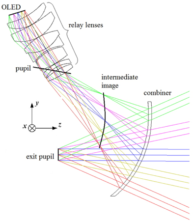
Developing a see-through head-mounted display (HMD) system with wide field of view (FOV) and good image quality has been a great challenge to designers for decades, since the design process of an HMD system requires an interdisciplinary approach [1]. Nowadays HMDs have undergone continuous and rapid development, due to the rapid advance of these interdisciplinary technologies, and thus have been widely used in many applications, such as virtual reality, augmented reality, training, medical visualization, and entertainment industries [2-5]. Figure 1 is the structure of a see-through HMD system. We can see that a see-through HMD system usually consists of an image source, an optical relay lens group, and a combiner. The image source is used to display information generated by the computer. The intermediate image is formed between the relay lenses and the combiner, and is positioned in the line of sight by reflection from the combiner. Through the combiner, the outside scene and the information generated by the computer can be simultaneously observed. The relay lens group is used to correct off-axis aberrations introduced by the tilted combiner.
Since being introduced decades ago, many different structures and methods to achieve see-through HMD systems with good imaging and wide FOV have been reported. There are many designs using a freeform surface to correct the aberrations and thus attain good image quality. However, they use a non-axial relay lens group or very complicated structures to correct the off-axis aberration introduced by the tilted combiner. These introduce extra difficulties during assembly of the HMD system. In 2010 Zhenrong Zheng
A design for a see-through HMD system with compact structure and large FOV is proposed. We achieved a coaxial structure in the relay lens group with a freeform surface as the combiner. The coaxial structure is simple and has loose tolerance requirements. The see-through HMD system we finally realized has a 40° × 30° FOV and 15-mm exit pupil diameter.
There are two design concepts for optical see-through HMD systems: One is based on a flat combiner, often providing an on-axis system, while the other has optical power, often providing an off-axis system. The off-axis design has many advantages: It minimizes the size of the system, avoids a ghost image, and provides a wider FOV. However, the off-axis system also has many disadvantages: It is difficult to correct the off-axis aberrations introduced by the tilt combiner, the structure of the relay lens group is complicated, and the tilt and decentering in the element make fabrication and assembly very tough.
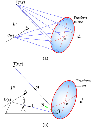
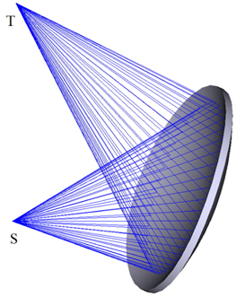
According to earlier structures of the HMD, the difficulty in correcting off-axis aberrations is due to the chief rays not converging to a single point after reflection from the combiner [8]. As shown in Fig. 2, in our design of the HMD system, the chief rays exiting from point S are meant to converge at a single point T after reflection from the freeform surface. In this paper, we generate the freeform surface by considering both coordinates and normals of the discrete data points [9].
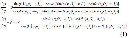
According to Ref. [10], a set of partial differential equations (PDEs) is introduced to describe the freeform surface as:

(
By solving Eq. (1) numerically via the finite differential method (FDM), global coordinates of a series of discrete data points on the freeform surface are obtained. From Snell’ law:

where Ni (i=1,2…I) is the corresponding normal of these data points.
In our design, an

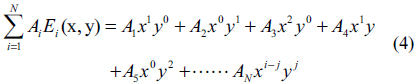
where Z(x, y) is the sagittal plane, k is the conic constant, c is the curvature of the surface, and r is the height above the optical axis; then

The number of polynomial terms is N=i(i+1)/2+j. Tilt of the freeform surface causes asymmetry about the XOZ plane of the optical system, but symmetry still exists about the YOZ plane; thus we keep even terms of x in
In the HMD system, the relay lens group plays an important role in correcting off-axis aberrations, such as coma, astigmatism, and asymmetrical distortion introduced by the tilted combiner [11]. To correct the off-axis aberrations, the tilt and decentering introduced in the relay lens element make fabrication and assembly very tough. To reduce assembly difficulty, the relay lenses are desired to be in a coaxial configuration. As shown in Fig. 1, the rays will form a bent image with tilt and decentering, which we call an intermediate image, between the relay lens group and the combiner. According to the Scheimpflug principle [12], we can introduce the tilt and decentering in the relay lens group about the axis AB to correct the tilted bent image.
Figure 4 is the original structure of the relay lens group. It consists of coaxial spherical lenses in six pieces with tilt and decentering about the optical axis AB. The image plane also has a small tilt about the optical axis.
2.3. The Original Structure of the HMD
The original structure of the HMD system is presented in Fig. 5: The combiner is a freeform surface with a 24.6° tilt and 29.2-mm decentering, and the relay lens group consists of coaxial spherical lenses in six pieces. The structure is compact, but has poor imaging quality. As shown in Fig. 6, the Modulation Transfer Function (MTF) is unacceptable low. Thus, further optimization must be performed.
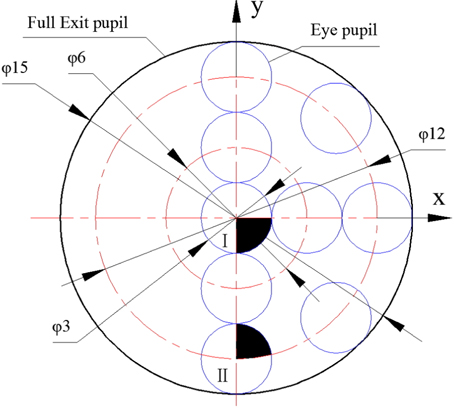
The optimization of the see-through HMD system can be mainly divided into two steps. First, we set the tilt and decentering of the relay lens group, the curvature of each relay lens, and the lens interval as the variables to optimize the system. By performing this step, we can correct the off-axis aberrations introduced by the combiner and meet the FOV requirement. Second, we aim to optimize the system to attain a good image quality. In a practical application, the pupil diameter of the human eye is approximate 3 mm; meanwhile, due to movement of the helmet, the 3-mm pupil is at a random position inside the 15-mm exit pupil. As shown in Fig. 7, when evaluating image quality, the reasonable MTF is not the value at the 15-mm exit pupil diameter, but the value at the random 3-mm eye pupil inside the 15-mm circle. All the parameters of the HMD system are set as the variables. Through optimization, the HMD system is meant to simultaneously satisfy the imaging requirements at the 15-mm exit pupil and the random 3-mm eye pupil, located within the exit pupil. Moreover, a 6-piece relay lens structure cannot correct off-axis aberrations well, so we add one more lens behind the second lens in the group, to correct the off-axis aberrations introduced by the combiner.
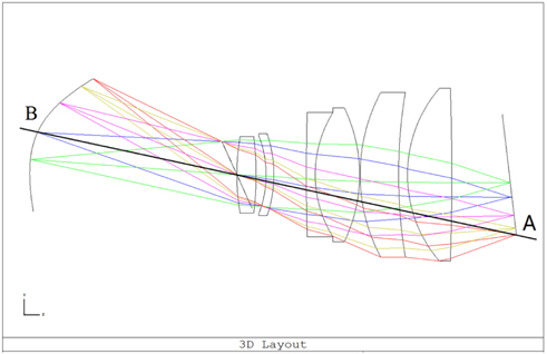
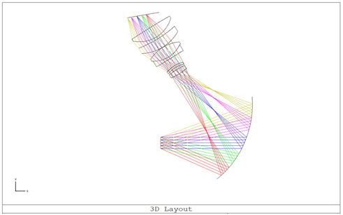
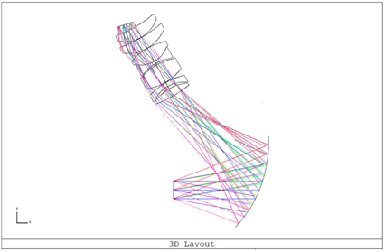
Figure 8 shows the ultimate structure of the see-through HMD system, which consists of a freeform surface combiner and 7-piece coaxial relay lens group. This HMD system has a compact structure with a 40° × 30° FOV and 15-mm exit pupil diameter.
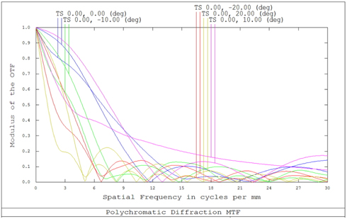
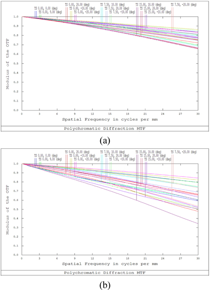
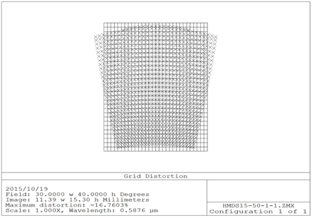
Figure 9 shows the best and worst MTFs among the different 3-mm-diameter evaluation points. The best MTF is about 0.7 at 30 lp/mm, corresponding to area I in Fig. 5. The worst MTF is about 0.5 at 30 lp/mm, corresponding to area II in Fig. 5. The average MTF is greater than 0.5 at 30 lp/mm. As shown in Fig. 10, the distortion is about -16.76%, while the FOV is 40° × 30°. The distortion is caused mainly by the tilt of the combiner and is difficult to correct optically. Correction of the distortion by digital-domain methods is strongly recommended [6].
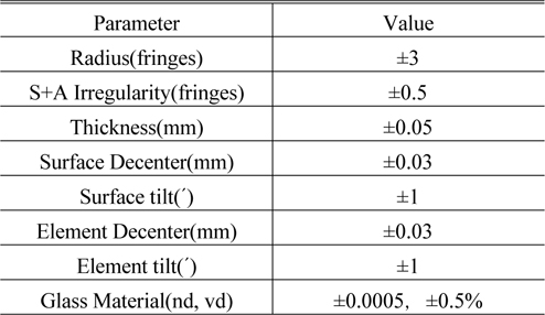
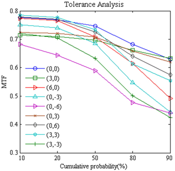
Tolerance analysis is an essential process in optical design for evaluating the processing difficulty of a system [13]. Table 1 shows the tolerance value of the HMD system calculated by the data using the Zemax software. We can see that the HMD system has a loose tolerance and thus can be easily assembled. Moreover, during the tolerance analysis we ran a Monte Carlo simulation 1000 times and used the normal distribution to analyze the MTF. Figure 11 is the cumulative probability for different MTF values under the conditions in Table 1. There is an 80% probability that the MTF is higher than 0.5 at 30 lp/mm. We can see that the HMD system has a loose tolerance and can be fabricated easily.
[TABLE 1.] Tolerance values of the HMD system

Tolerance values of the HMD system
A design for a see-through head-mounted display (HMD) with a freeform surface is proposed. We realize a simple HMD system with 40° × 30° FOV and 15-mm exit pupil diameter. The HMD system we have realized includes a combiner and 7-piece coaxial relay lens group. We use a freeform surface as the combiner, which benefits a compact structure and good image quality. Moreover, the coaxial structure of the relay lenses avoids decentering and tilt in the group, and benefits the assembly of the relay lenses.