In this paper, parameters related with partial discharge (PD) were analyzed in SF6 gas under AC and DC voltages. Three electrode systems (protrusion on conductor, protrusion on enclosure, and free particle) were fabricated to simulate PD defects in a gas-insulated switchgear (GIS). All electrode systems were filled with SF6 gas at 0.5 MPa. PD pulses were detected using an oscilloscope and a data acquisition (DAQ) based on IEC 60270. To analyze the PD characteristics under AC and DC voltages, parameters such as discharge inception voltage (DIV), discharge extinction voltage (DEV), pulse magnitude, repetition rate, and T-F map were compared. From the experimental results, PD was revealed to have different characteristics under AC and DC, and these results may be useful for diagnosis of power facilities operated under HVDC.
Gas insulated switchgears (GIS) are widely applied in power systems owing to the advantages of high reliability, compact size, and safety. The GIS consists of a busbar, a circuit breaker, a voltage and current transformer, a lightning arrester, and other components. SF6 gas is filled and sealed in the GIS to maintain high insulation. However, insulation defects caused during the manufacture, transportation, and assembly processes result in accidents of the GIS. Due to the large capacity per unit, such accidents can cause significant damage [1,2]. Partial discharge (PD), which can indicate defects in the insulation system or causes of low insulation performance, has been studied globally for a long time in order to prevent GIS insulation accidents. PD detection methods mainly include the electrical method based on IEC 60270, the ultra high frequency (UHF) method based on radiated electromagnetic waves, and the acoustic method based on measurement of the acoustic emission signal [3-6]. The phase resolved partial discharge (PRPD) method that analyzes the phase of discharge occurrence (Φ), discharge magnitude (q), and repetition rate (n) is widely used for the identification of defect types. However, at present, PD detection and analysis methods primarily involve the application under AC voltage, while PD under DC voltage remains under investigation [7,8].
The high voltage direct current (HVDC) solution has been widely applied for effective power transmission, particularly in Northern Europe where countries border each other closely and islands are common. Furthermore, with increases in the number of wind generation farms, the interest in HVDC technology is growing rapidly [7,9]. Therefore, it is essential to monitor and diagnose HVDC power facilities to ensure their reliable operation. Owing to the absence of phase information, the well-known PRPD method used for analyzing PD under AC cannot be applied under DC. As a result, new parameters for the diagnosis of insulation performance under HVDC are required.
In this paper, three electrode systems such as a protrusion on conductor (POC), a protrusion on enclosure (POE), and a free particle (FP) were fabricated to simulate major insulation defects in GIS for the comparison of PD parameters under AC and DC. The discharge inception voltage (DIV), discharge extinction voltage (DEV), pulse magnitude, repetition rate, and T-F map extracted from PD pulses were analyzed.
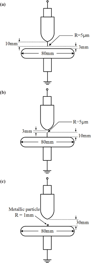
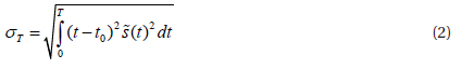
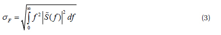
GIS accidents are mainly caused by loose contact, defects in the solid insulator, and particles generated in the assembly and installation processes. Insulation defects can easily be detected during a field test. However, if unchecked, these insulation defects can lead to the breakdown of the GIS. Further, discharge presents different patterns depending on the types of defects. Therefore, it is important to analyze discharge characteristics in various types of defects in order to better identify the defects and take proper action [1,10]. In this paper, three types of electrode systems (POC, POE, and FP) were fabricated to simulate typical insulation defects in GIS, which are shown in Fig. 1.
POC was used to simulate a protrusion or attached conductive material on the GIS conductor, and POE represented a defect on the surface of the GIS enclosure. In both POC and POE, the curvature radius and length of the needle electrode were 5 μm and 10 mm, respectively. The plane electrode had a diameter of 80 mm and a thickness of 20 mm. To prevent concentration of an electric field, the plane electrodes had rounded edges. The distance between the needle and the plane electrode was 3 mm. The FP made by an aluminum ball with a diameter of 1 mm was used to simulate a free moving conductive particle dropping from the enclosure or conductor of the GIS. In the FP, the distance between two electrodes was 30 mm. An enclosure was designed to keep the aluminum ball inside the electrode system when the applied voltage was raised. All electrode systems were filled with SF6 gas at 0.5 MPa to simulate GIS operating conditions.
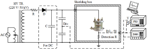
The experimental setup is shown in Fig. 2. An HVDC source comprising a transformer of 50 kVmax, a high voltage diode of 100 kV, and a capacitor of 0.5 μF was used. The applied voltage was measured using a voltage divider with a ratio of 10,000:1. To reduce external interference, electrode systems were placed in a shielding room. This experimental system was designed to avoid corona occurring around the high voltage conductor. PD pulses were detected through a 50 Ω non-inductive resistor and analyzed by an oscilloscope with a sampling rate of 5 GS/s and a data acquisition (DAQ) with a sampling rate of 250 MS/s based on LabVIEW.
The TF method is the analysis of PD in time and frequency domain by extracting equivalent time σT and equivalent frequency σF from each pulse. The detected signal
σT and σF are the standard deviations which mean the effective range of time around the time gravity and the effective range of the bandwidth around the frequency gravity, respectively, and are given by:


where is the Fourier transform of normalized signal and

Based on above equations, TF maps of PD pulses in each electrode system under AC and DC can be created [11,12].
DIV and DEV in each electrode system were measured five times. In order to reduce the influence of residual space charge, the time interval of voltage application was set to ten minutes.
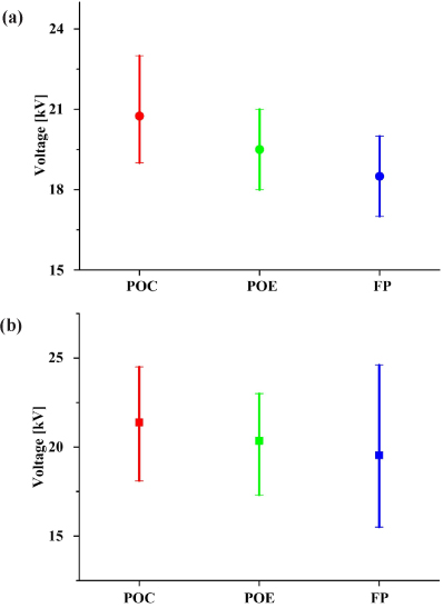
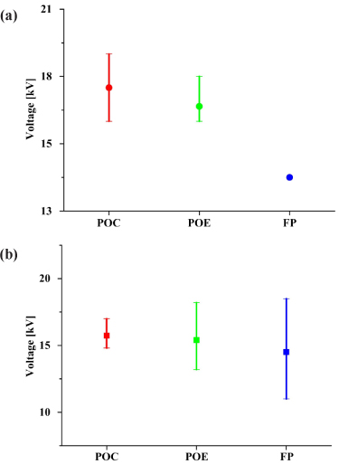
The DIV and DEV of the three electrode systems are shown in Figs. 3 and 4, respectively. The average DIV and DEV in POC under AC were 20.1 kV and 17.5 kV, respectively, and those under DC were 21.4 kV and 15.4 kV, respectively. In POE, PD occurred at an average voltage of 19.5 kV and extinguished at 16.8 kV under AC. The DIV in POE under DC was 20.2 kV, which was higher than that under AC, and the DEV which was lower than that under AC was 15.4 kV. In FP, discharge under AC and DC started at 18.5 kV and 19.5 kV, respectively, and it extinguished at 14.7 kV and 14.5 kV, respectively. Since the aluminum ball moved in the electrode system, the differences between the maximum and minimum of DIV and DEV were high. Under AC voltage, the particle moved when the applied voltage was increased. When the applied voltage was significantly high, the particle shuffled on the surface of the plane electrode and then jumped in the electrode system. However, the particle jumped directly without the moving and shuffling phenomenon under DC.
In each electrode system, the DIV measured under DC were higher than those measured under AC while the DEV under DC were lower. In addition, the DIV were higher than the DEV under both AC and DC.
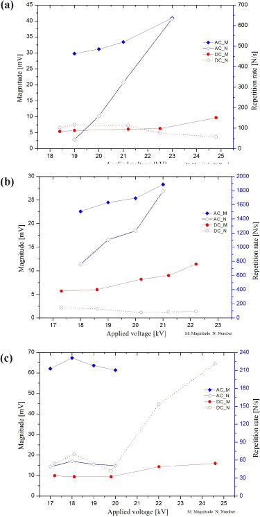
Figure 5 shows the pulse magnitude and repetition rate of each electrode under AC and DC. In POC, the pulse magnitude and repetition rate under AC increased with applied voltage. The repetition rate at DIV (19.0 kV) was as low as 50 N/s; however it increased rapidly as the applied voltage was raised and it reached 633 N/s at 23.0 kV. However, the repetition rate under DC did not change greatly from 18.4 kV to 21.2 kV, and it decreased slightly when the applied voltage was over 21.2 kV.
In addition, the discharge magnitude increased with applied voltage, and a rapid increase was observed after the DC voltage reached 22.5 kV. The trends in POE were similar to POC: an increase in the pulse magnitude and repetition rate under AC with applied voltage, a near constant repetition rate under DC, and an increase in pulse magnitude. However, the increase rate of pulse magnitude under DC in POE was somewhat higher than that in POC. The pulse magnitude and repetition rate under AC and DC in FP were irregular with the increase of applied voltage, which were different from POC and POE. This was due to the movement and jump of the particle in the electrode system.
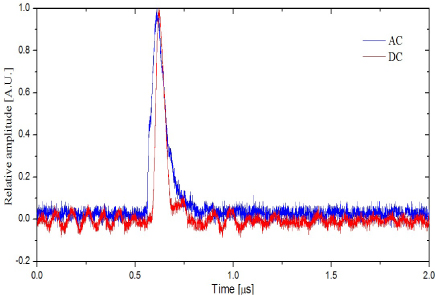
Figure 6 shows an example of detected PD pulses in time domain in POC under AC and DC. The width of PD pulse under AC was greater than that under DC. Such measured waveforms were analyzed in the time and frequency domain by the T-F method.
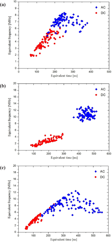
Figure 7 illustrates the T-F map of each electrode. In POC, the frequency ranges under AC and DC were 5~8.5 MHz and 1.5~6 MHz, respectively. The pulse widths were distributed in 150~380 ns and 60~250 ns in the time domain. Under AC and DC, the frequency ranges overlapped and the pulse widths were similar. As shown in Fig. 7(b), the frequency of PD pulses in POE were distributed in 8~13.5 MHz and 1~5 MHz under AC and DC, respectively, without overlapping. The ranges of pulse width were 380~530 ns and 80~300 ns. The PD pulses under DC were distributed with a lower frequency and a wider range of pulse width than those under AC. The T-F map of FP is shown in Fig. 7(c). PD pulses under AC were distributed with a wide range of pulse width of 150~570 ns and a frequency range of 4.5~12.5 MHz. While under DC, the T-F map was distributed in a narrow area. The range of pulse width and frequency were 50~160 ns and 1~5.5 MHz, respectively.
Under both AC and DC, T-F maps of electrode systems were distributed in different ranges, by which the types of defects can be discriminated.
This paper studied the comparison of parameters related with PD in SF6 gas under AC and DC. Typical PD sources in GIS were simulated by three electrode systems: a POC, a POE, and an FP. Further, parameters such as DIV, DEV, pulse magnitude, repetition rate, and T-F map were compared in each electrode system to analyze PD characteristics under different types of voltages. In the three electrode systems, the DIV under DC were greater than those under AC, while the DEV under DC were lower. In addition, the DIV were greater than the DEV under both AC and DC. In POC and POE, the pulse magnitude and repetition rate increased with applied voltage under AC. Under DC, the pulse magnitude and repetition rate maintained similar values when the applied voltage was not too high. As the voltage was raised, the pulse magnitude increased while the repetition rate decreased slightly. Irregular relationships between pulse magnitude or repetition rate and the applied voltage under both AC and DC were observed in FP due to the movement of aluminum particle in the electrode system. In addition, the T-F map in each electrode system presented obviously different patterns in the pulse width and frequency domain under AC and DC. It was confirmed that it is able to identify defect types using the T-F map. The comparison of PD-related parameters under AC and DC in this paper may assist in the diagnosis of power facilities operated under HVDC.