We present a new scheme for optical encryption of a binary image. In our method, the original binary data page is first divided into two identical pages. In each data page, the “on” and “off” pixels are represented by two discrete phases that are 90° apart. The first page corresponds to the phase conjugation of the second page, and vice versa. In addition, the wavefront of the two data pages is changed simultaneously from planar to spherical, for better encryption. The wavefront modification is represented by an extra phase shift, which is a function of position on the wavefront. In this way the two separate pages are both encrypted, and therefore the pages cannot be distinguished in a CCD. If the first page is used as an encrypted data page, then the second page is used as the decryption key, and vice versa. The decryption can be done by simply combining the two encrypted data pages. It is shown in our experiment that encryption and decryption can be fully accomplished in the optical domain.
Optical encryption systems [1, 2] have been widely researched in recent years, since Refregier and Javidi proposed the double- random phase encoding technique, in which a primary image is converted into stationary white noise using two random-phase masks [3, 4]. The double-random phase encoding could be improved by inserting the mask in the fractional Fourier domain [5]. Han
In this paper, we present an all-optical encryption and decryption scheme for a two-dimensional binary data page. We first transform the “on” and “off” pixels of the binary image into right- and left-handed circular polarizations. Then, two orthogonal linear polarizers are used to separate the original image into two independent phase images, each of which is fully encrypted such that the on and off pixels have the same intensity and polarization. It is shown that the decryption can be easily done by optically combining the two phase images. Our scheme is demonstrated by optical experiments, and the principle is explained by Jones matrices. The feasibility of our scheme is proved by measuring the bit error rate (BER) of the encrypted and decrypted images. It is experimentally shown that the interference between one of our encrypted images and a third plane wave cannot restore the original binary data.
II. EXPERIMENTAL SETUP FOR PHASE MODULATION
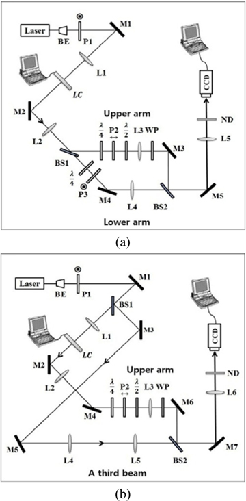
Our experimental setup is shown in Fig. 1(a). The encryption and decryption of a binary data page are performed optically, with the help of the circular polarization of the laser beam. A He-Ne laser of 633 nm is used for the light source. The laser beam is first expanded by a beam expander (BE) and converted to a large Gaussian beam. The curvature of the wavefront is later changed by lens L1 so that the wavefront itself is an encryption key, in addition to the phase modulation of the wavefront. Polarizer P1 polarizes the beam vertically with respect to the surface of the optical table, or the page. After its curvature is modified by lens L1, the beam passes through the TN-LC panel that is taken from a commercial beam projector (Sony VPL-EX100). The red LC panel used in our experiment has 1024×768 pixels. Since the LC panel is employed here for phase modulation, it is used without the crossed polarizers that were essential for the intensity modulation in the original beam projector.
A two-dimensional binary image is displayed on the LC panel, using a computer. An off pixel in the image, representing a grayscale value of zero, makes the input laser beam pass through the LC panel with no change in its polarization, while an on pixel in the image, representing a grayscale value of 255, rotates the polarization of the output beam from the LC panel by 83°, relative to that of the input beam. Under our experimental conditions, the rotation of the polarization is not 90°, and thus it is very difficult to make the beams of on and off pixels be the right-hand and left-hand circular polarizations, respectively, at the same time. To overcome this problem, we use two quarter-wave plates, as shown in Fig. 1(a). The quarter-wave plate in the upper arm is aligned to give the beam of the on pixel exact right-hand circular polarization, whereas the other quarter-wave plate in the lower arm is used to give the beam of the off pixel exact left-hand circular polarization. The polarizer P2 in the upper arm is used to collect only the horizontal components of the beams of the on and off pixels, whereas the polarizer P3 in the lower arm is used to collect only the vertical components. Then, using the half-wave plate, the beam polarization is rotated by 90° in the upper arm, so that all beams are vertically polarized in the upper and lower arms. The wave plate (WP) is used to change the relative phase between the beams in the upper and lower arms. Lens L2 forms the image of the LC panel at the position of lens L3, and then lens L5 forms a reduced image of the LC panel at the CCD, which has 640×480 pixels. One bit (or block) in the binary image falling on the CCD covers 22×22 CCD pixels. Due to lenses L3 and L4, the diameter of each beam is almost unchanged as it propagates toward lens L5.
It is noted that the images in the upper and lower arms respectively represent two encrypted images. Each can be separately recorded on the CCD by blocking the other beam. Combining the images of the upper and lower arms at the CCD yields the decrypted image.
III. PRINCIPLE OF PHASE MODULATION
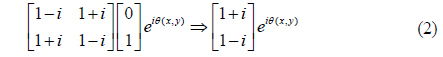
When the vertically polarized laser beam passes through the LC panel, the polarization of the output beam is spatially modulated according to the binary pattern fed into the LC panel. An on pixel makes the output beam horizontally polarized, its polarization state being represented by the Jones matrix [1, 0]T. On the other hand, an off pixel causes no change in the output polarization, its polarization state being represented by the Jones matrix [0, 1]T. If an image-bearing beam passes through a quarter-wave plate, the beams of the on and off pixels respectively become right- and left-hand circularly polarized. The polarization state of the beam of an on pixel, which is right-hand circularly polarized, is represented by the Jones matrix as
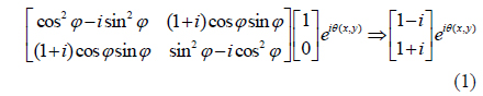
In this equation φ is the rotation angle of the slow axis of the quarter-wave plate relative to the surface of the optical table, which is 45° in the ideal case. The phase term θ(x, y) represents the relative phase difference among the on pixels located at different points in the transverse plane, such as (x1, y1), (x2, y2), and so on. The relative phase is due to the curved wave front of the image-bearing beam. (The constant ½ is omitted on the right side of Eq. (1), because it is irrelevant to the polarization state.) Similarly, after passing through the quarter-wave plate, the polarization state of the beam of an off pixel, which is left-hand circularly polarized, is given by the Jones matrix as

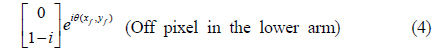
Next, as explained earlier, the image bearing beam is split into two by a beamsplitter. In the lower arm, after the polarizer P3, the polarization states of the on and off pixels are respectively given as
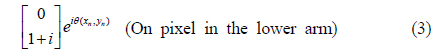

Note that the second element of the column matrix in Eq. (3) is equal to that of the column matrix in Eq. (1). Similarly, the second element of the column matrix in Eq. (4) is equal to that of the column matrix in Eq. (2). Either the on pixel in Eq. (3) or off pixel in Eq. (4) may have an extra phase shift, depending on the position on the wavefront. In these equations
In the upper arm the beam is horizontally polarized, due to polarizer P2. After the polarizer, the Jones matrices of the on and off pixels are given as
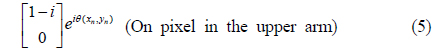
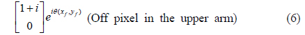
Note that the first element of the column matrix in Eq. (5) is equal to that of the column matrix in Eq. (1). Similarly, the first element of the column matrix in Eq. (6) is equal to that of the column matrix in Eq. (2).
Next, the beam is vertically polarized using a half-wave plate. In the upper arm, therefore, the Jones matrices of the on and off pixels are finally given as
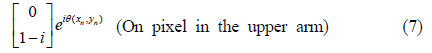
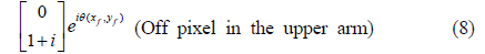
In the lower arm, for example, the image-bearing beam contains on and off pixels whose polarization states are represented by Eqs. (3) and (4). Both beams are vertically polarized, although they are 90° phase-shifted with respect to each other, except for the phase difference θ(x, y). The two beams have the same intensity, such that they are indistinguishable at the CCD. The binary image is thus encrypted in the lower arm. By the same token, the binary image with the Jones matrices in Eqs. (7) and (8) is encrypted in the upper arm.
The original binary data page is phase modulated, and therefore encrypted in both the upper and lower arms in our experimental setup. Decryption can be performed simply by combining the encrypted image with its counterpart.
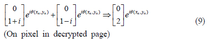
In our experiment, the beams in the upper and lower arms are combined at beamsplitter BS2 for decryption. The Jones matrices are shown in Eqs. (9) and (10). In this case, the on pixels in the upper and lower arms are combined such that the polarization state of the combined beam is given by the sum of Eqs. (3) and (7); the Jones matrix is given by

Similarly, when the off pixels in the upper and lower arms are combined, the polarization state is given by the sum of Eqs. (4) and (8); the Jones matrix is given by
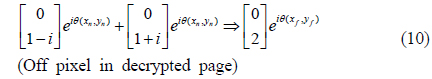
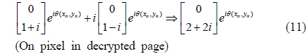
Since the polarization states of the on and off pixels are the same as in Eqs. (9) and (10), it is impossible to distinguish on from off pixels in the combined image; the image is still encrypted. To decrypt the image, we insert an additional wave plate in the upper arm, which causes an extra phase delay of 90° in the beam. Then, from Eqs. (9) and (10), the polarization states of the on and off pixels in the decrypted page are given by

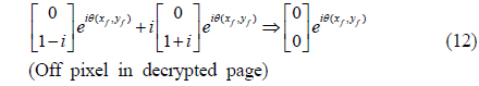
Note that the second matrices on the left-hand sides of Eqs. (11) and (12) are multiplied by
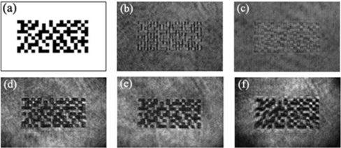
A TN-LC panel of 1024×768 pixels is used in our experiment. We use a random checkerboard of 10×20 blocks, each representing a bit, as shown in Fig. 2(a). A white block represents an on pixel, while a black one represents an off pixel. A single block is made of 35×35 LC pixels. Under our experimental conditions, one block covers 22×22 pixels of the CCD.
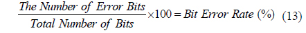
Figures 2(b) and 2(c) show two images encrypted in the upper and lower arms respectively. To check the degree of encryption, we measure the BER of the encrypted image, which is defined as

The BERs are measured as 44.2% and 59.6% respectively for the two encrypted images. Since a BER of 50% indicates the best case for the encryption, the measured BERs show that both encryptions in the upper and lower arms are excellent in our experiment. Figure 2(d) shows the decrypted image of the binary pattern obtained by combining the images in the upper and lower arms after an additional phase delay has been imposed in the upper arm. In this process, the beams of the on pixels interfere constructively (see Eq. (11)), while those of the off pixels interfere destructively (see Eq. (12)). The BER is measured as 3.7% in the decrypted image.
We repeated the experiment of encryption and decryption by changing the curvature of the laser beam, which is done by moving lens L1 forward or backward. Figure 2(e) is the decrypted image when lens L1 is moved 20 cm toward the LC panel, while Fig. 2(f) is the decrypted image when lens L1 is moved 20 cm backward. The BERs are measured to be 2.4% and 5.5%, respectively, in this case. It is noted that the decryption is not affected by the change in curvature of the encrypted beam in our scheme.
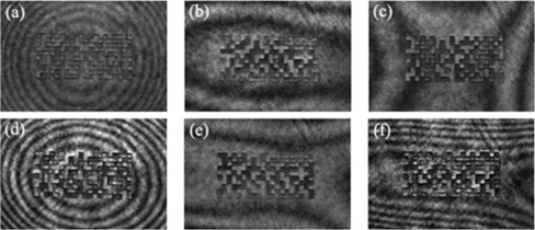
Next, we tried to decrypt the image using a third beam. With reference to Fig. 1(b), when a simply expanded laser beam is used to decrypt the image in the upper arm, lenses L4 and L5 are removed, and the interference between two beams yields the image at the CCD, as shown in Fig. 3(a). The BER is measured as 48.3%, meaning that the image has not been decrypted. To improve the BER, we employ lenses L4 and L5 and change the distance between them to make the curvature of the third beam fit that of the beam in the upper arm. Figure 3(b) is the best image we can obtain, for which the BER is measured as 15.3%.
We then displace lens L1 forward or backward to change the curvature of the beam incident upon the LC panel, or the beam used to encrypt the image. Figures 3(c) and 3(d) are the images decrypted using the simply expanded laser beam; during the encryption, lens L1 was moved 20 cm forward for Fig. 3(c), and 20 cm backward for Fig. 3(d). The BERs for the decrypted images are measured to be 42.9% and 41.4%, respectively. The BERs show that decryption cannot be accomplished using a simply expanded laser beam. Figures 3(e) and 3(f) are the best decryptions we could obtain by adjusting lenses L4 and L5. In this case, the BERs are improved to 7.8% and 23.5%, which are still higher than that of the image decrypted using our method.
We have proposed a new scheme for optical encryption of a binary image. In our method, a binary data page is converted into a set of two phase images. In each phase image, the on and off pixels are 90° phase-shifted with respect to each other. Furthermore, the on pixel in a phase image is 90° phase shifted with respect to its counterpart in the other phase image. Since in a phase image the on and off pixels have the same intensity, they are indistinguishable to an intensity detector, and the original binary image is thus encrypted.
In our method, decryption is performed easily by combining two phase images. An intruder might try to decrypt the image by interfering our phase image with a third beam―a plane wave, for example. However, since the curvature of the beam is changed during encryption in our method, a complete decryption is very difficult and time-consuming, even if the exact curvature of the beam is known. In our method, the BER of the decrypted image was as low as 3.7%. Even when we changed the curvature of the encryption beam, the BER of the decrypted image did not change much. On the other hand, the BER of the image decrypted by interfering the phase image with a plane wave was measured to be 48.3%, and it improved only to 15.3% when two lenses were used to fit the curvature of the encryption beam. When the curvature was changed during the encryption, decryption with a third beam required a lot of optical adjustment to fit the curvature using two lenses. In this case, the BER ranged from 7.8% to 23.5%.
In conclusion, we propose a new system of optical encryption of binary data. In our method, the wavefront of a laser beam is phase modulated according to the binary data, and the curvature of the wavefront is changed for different data pages. The image-bearing beam is then split into two phase images, such that they are independently encrypted. Decryption is performed by optically combining the two phase images.