This paper presents a design method for improving the low relative illumination and large distortion due to widening the field of a system. A tele-centric optical system in image space was suggested to increase the relative illumination. Through the analyses of the third-order aberrations affected by introducing aspherical surfaces, we have proposed a method to determine analytically what surface should be aspheric to correct each aberration effectively. By utilizing this method to design a wide field lens, a tele-centric wide field lens with f-number of F/2.0 was obtained. Even though the field angle is 120 degrees, it has a very low distortion less than -2% and high relative illumination more than 73.7%. In conclusion, this analytic method for selecting aspherical surfaces is expected to serve as a useful way to find design solutions.
In modern optical instruments such as CCTV and black box cameras, a wide field system is widely used. Such a system is required to cover an extremely wide field, normally more than 120 degrees, without additional instruments. Because of its inherent wide angle, however, the large incidence angles of rays into an image plane significantly reduces the illumination around the margin field and induces large aberrations, especially great distortion being proportional to the cube of field size [1]. Many wide field lenses subtending the field angle of 120 degrees have been reported, but their distortions are from −40% to −50% [2-4]. These distortions are so large that the images are significantly distorted, to a level that needs soft-ware to correct distorted images.
To overcome these problems, in this paper we propose a design method for improving the low relative illumination and large distortion due to widening the field of a system. A tele-centric optical system in image space is suggested to reduce the incidence angles of rays into an image, which results in increasing the relative illumination [5-8].
All the third-order aberrations can be corrected by introducing aspherical surfaces. Through the analyses of the third-order aberrations affected by aspherical parameters [9-11], this study proposes a method to determine analytically the aspheric surface that is most effective to correct each aberration. From the aberration analyses, aspherization of rear surface of the 1st lens is confirmed to be most appropriate for distortion correction.
By utilizing this design method, a tele-centric wide field lens with field angle of 120 degrees has been obtained. In addition, it has a very small distortion less than −2% at the margin field.
II. DESIGN OF A TELE-CENTRIC SYSTEM
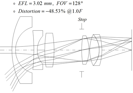
In this study, to overcome low illumination due to wide field, a tele-centric optical system in image space is suggested to improve the relative illumination. The starting wide field lens is selected from the patented lens composed of two groups, as shown in Fig. 1 [2]. This lens can realize the wide field, but has great distortion of −48.53% at the margin field. The goal of our study is to design an optical system having small distortion less than ±2% and higher relative illumination at all fields, by using the proposed design concepts.
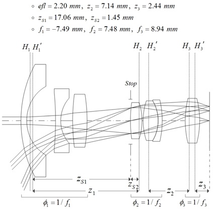
In Fig. 1, the configuration of a negative first group and positive second group gives a retro-focus system so that it is suitable for a wide field lens. Our tele-centric system can be realized by adding a lens element before the image plane, as shown in Fig. 2.
By denoting the distances between adjacent principal planes as


Solving Eqs. (1)~(3) simultaneously results in an expression for the unknown parameters of
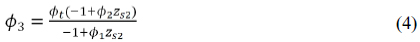
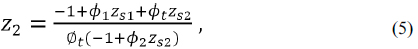
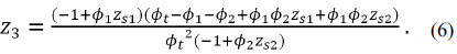
Figure 2 illustrates the tele-centric system found by locating the element designed from Eqs. (4)~(6).
III. PROJECTION METHOD IN A WIDE FIELD LENS
The full field angle of the system is aimed to 120°, therefore the gnomonic projection method is generally used to define the image size [6, 12-13]. The paraxial image height () and distortion (%) are respectively given by

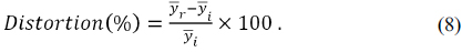
If the real image height () and full field angle (2

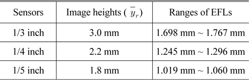
Ranges of EFLs for several image sensors to correct distortion within ±2% at field angle of 120 degree
IV. ANALYSES OF THE THIRD-ORDER ABERRATIONS OF A LENS SYSTEM
The third-order aberration coefficients for spherical aberration (
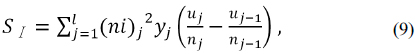
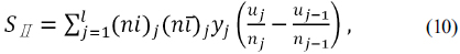
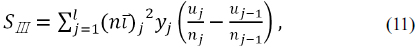
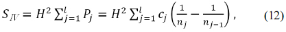
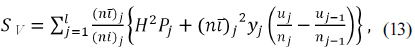
where
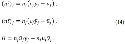
In these equations,
The conic constant (
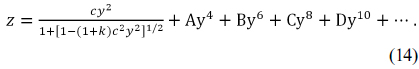
Introducing the conic constant (


where

Therefore the conditions that all the third-order aberrations except Petzval blur are corrected, by combining Eqs. (9)~(13) with Eqs. (15)~(18), are expressed as follows:


V. DESIGN FOR AN INITIAL WIDE FIELD LENS USING THE THIRD-ORDER ABERRATION ANALYSES
In this research, unlike general methods correcting the aberrations using aspheric surfaces, we suggest approaches to analytically determine what surface is most effective to correct each third-order aberration. Before determining these corrections, Petzval curvature should be firstly removed from the spherical lens, not the aspheric.
5.1. Petzval Field Curvature Correction
In Section Ⅱ, adding a positive element in front of an image gave a tele-centric system, but in parallel it made the system have a much more negative Petzval sum. Since the selection of optical glasses is limited, it is better to change the curvature than the refractive index so that the Petzval sum can be easily corrected.
Because the first group is located before the stop, even if its parameters are changed, the tele-centric system is still effective. To have zero Petzval sum, the radius of curvature of the jth surface is required to have the value given by Eq. (24).
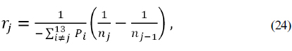
where
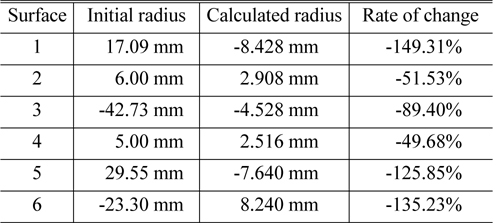
In Eq. (24), the denominator denotes the Petzval sum except the Petzval curvature of the jth surface. Consequently, the radius of curvature of each surface can be calculated to have zero Petzval sum, and Table 2 lists the calculated radius of curvature of each surface to make the Petzval sum be zero.
[TABLE 2.] Calculated radius of curvature of each surface to correct the Petzval sum

Calculated radius of curvature of each surface to correct the Petzval sum
To have zero Petzval sum in Table 2, changing the radius of the 4th surface (
[TABLE 3.] Radii of curvature to correct the Petzval sum

Radii of curvature to correct the Petzval sum
5.2. Spherical Aberration Correction Using Conic Constant
Among the third-order aberrations, we firstly correct spherical aberration using an aspherical surface. By introducing an aspheric to the jth surface, the condition that spherical aberration is corrected is expressed in terms of a conic constant (

For
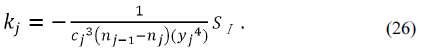
Introducing an aspheric to the 7th surface at stop has advantage in that any aberration is not changed, except for spherical aberration. For spherical aberration to be corrected, from Eq, (26), the conic constant of the 7th surface should be
5.3. Correction of Spherical Aberration and Distortion
By aspherization of the 7th and other surfaces, we can simultaneously correct spherical aberration and distortion that is the most troubling aberration in a wide field system. From Eqs. (15), (18), (20), and (23), the following equations must be satisfied for these aberrations to be corrected:


Assuming that two fourth-order coefficients(
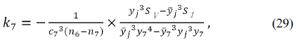
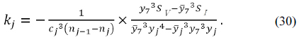
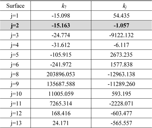
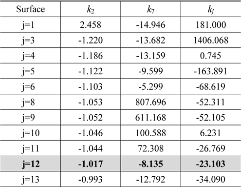
Table 4 shows the conic constants of
[TABLE 4.] Conic constants to correct spherical aberration and distortion

Conic constants to correct spherical aberration and distortion
5.4. Correction of Spherical Aberration, Distortion, and Astigmatism
The 2nd and 7th surfaces are aspherized to correct distortion and spherical aberration. By introducing an aspheric into another surface, the conditions for correction of astigmatism and the above two aberrations are given by


Assuming that three fourth-order coefficients (
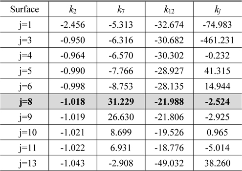
The conic constant
Conic constants to correct distortion, spherical aberration, and astigmatism simultaneously
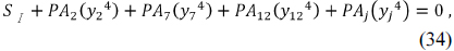
5.5. Correction of All Third-Order Aberrations
Among the third-order aberrations, the Petzval sum was already corrected using two negative surfaces of the front group, and three aberrations other than coma were also removed by aspherization of three surfaces. By introducing another aspherical surface, the conditions correcting all the third-order aberrations are given by
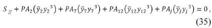
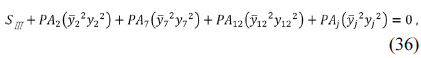
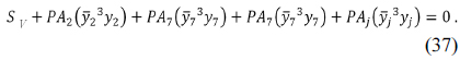
Through the same design process of Section 5.4, solving four simultaneous equations of Eqs. (34)~(37) provides the values of

Conic constants to correct distortion, spherical aberration, astigmatism, and coma simultaneously
In the aberrations correction of Section 5.4, the best three surfaces are independently selected to correct three aberrations so that three aspheric lenses are required. In this study, we hope to use just three aspherical lenses without an additional aspherical lens. Therefore, the 1st, 8th, and 13th surfaces can be aspherized to correct coma. Since the 8th surface is near to a stop, the height of a chief ray is low, and that of an axial marginal ray is high. Therefore, aspherization of the 8th surface is very useful in removing coma aberration. From Table 6, the design parameters of
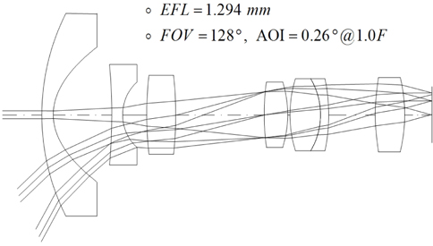
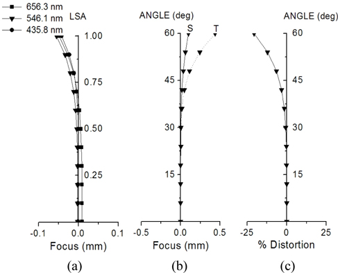
Figure 3 shows a tele-centric optical system of which all the third-order aberrations are corrected, and Fig. 4 illustrates the ray aberrations of this system.
VI. COMPLETE WIDE FIELD LENS DESIGN
A tele-centric system of Fig. 3 has been designed to have the focal length of 1.294 mm, which is proper to realize the system having distortion of ±2%, if a 1/4-inch image sensor is used, as shown in Table 1. In the initial design, however, we corrected the third-order aberrations useful in reduced aperture and field so that practicable aperture and image size were small. If current specifications for a wide angle camera are to be met, the aperture and field size should be increased. The aperture is extended to F/2.0. The full field size is increased to 4.4 mm for a 1/4-inch CCD, which corresponds to 120 degree at focal length of 1.294 mm. In an extended aperture and field system, however, there are higher-order aberrations that are not corrected in the previous design, as shown in Fig. 4.
In order to improve the overall performance of the lens system with an extended aperture and field, we balance the aberrations of the starting lens given in Fig. 3 by using the higher-order aspheric coefficients not used in correction of the third-order aberrations.
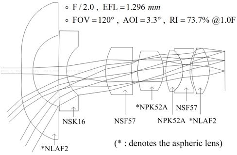
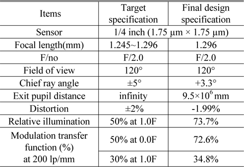
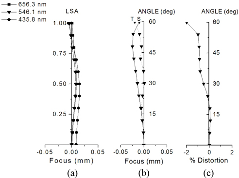
Finally, a wide field lens having good performance is obtained. The layout of the system is shown in Fig. 5. Table 7 lists the specifications of this lens. Compared to Fig. 4, all residual aberrations are significantly reduced, as shown in Fig. 6. Especially distortion is dramatically reduced to -2%, from 48.53% of the patented lens. Even though this system covers an extremely wide field angle of 120 degrees, distortion is so small that the distorted image is nearly not seen.
[TABLE 7.] Specifications for a wide field camera lens

Specifications for a wide field camera lens
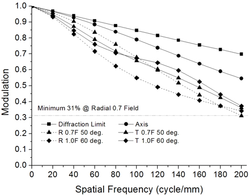
Figure 7 shows the modulation transfer function (MTF) characteristics of the system. The MTF at 200
Even though it is extremely wide angle, the total track of the lens is just 23.56 mm, and large aperture with F/2.0 is realized. Consequently, this system has enough performance to fulfill the requirements of a modern wide field camera.
By use of the third-order aberration analyses and tele-centric design, in this paper large distortion and low relative illumination due to widening the field have been solved. To correct all the third-order aberrations without changing configuration, aspheric lenses are most effective so that they are used to correct aberrations.
In a design using general software like Code-V, the designer usually determines the surfaces to be aspherized from empirical judgments. Through the analyses of the third-order aberrations affected by aspherical parameters, however, this study proposed the method to determine analytically what surface should be aspheric to correct each aberration effectively. By utilizing this method to design a wide field lens, an initial tele-centric system was obtained, of which all the third-order aberrations were removed. To improve the performance of the starting lens in the extended aperture and field, three aspheric lenses are used to balance the residual aberrations.
A wide field lens with a total track of 23.56 mm, whose aperture was F/2.0, was obtained. In addition, even though this lens subtends the field angle of 120 degree, it has a very low distortion less than −2%. The optical system developed in this work performs reasonably as a compact camera system with wide field angle. In conclusion, this analytic method for selecting aspherical surfaces is expected to serve as a useful way to find design solutions.