Squirrel cage induction motors have mostly been used for their small capacity because the starting torque is smaller than the starting current during start-up. However, as more and more mid-to-large capacity motors are developed, the demands for improvements in performance characteristics have also increased. In this study, the starting characteristics of squirrel cage induction motors were analyzed based on the rotor materials and shapes using a finite element method to provide design data suitable for different use purposes and capacities. We further completed analysis by combining electromagnetic equations deduced from Maxwell’s equations and the circuit equations of stators and rotors. A moving coordinator was introduced to rotate the rotor during the analysis, and the torques calculated via the finite element method were combined with the motion equations to calculate the position and angular velocity of the rotors at the next time, thereby analyzing the transient characteristics. The analysis results of the transient characteristics were applied to a 3-phase 4-pole 5-hp induction motor to calculate the starting torque, speed, and rotation angle of the rotors. In the reference model, the materials and shapes of the rotor slot were changed to copper and silicon copper and a deep slot, shallow slot, and long-neck-shaped slot.
Two main methods are used in the analysis of induction motors: (1) the equivalent magnetic circuit method [1-3] and a numerical analysis of the electromagnetic field [4-7]. The equivalent magnetic circuit method has several advantages that can shorten the time required to analyze the characteristics and has relatively satisfying results near the speed in synchronicity with the rotation speed of the device. On the other hand, the equivalent magnetic circuit method also has several drawbacks: it cannot be directly applied to induction motors that are asymmetrically electromagnetic, and cannot take the magnetic saturation of the cores into consideration because of the assumption that all physical quantities are symmetrical and every phase is sinusoidal. Another drawback is the cumbersome process of induction motor design, requiring changing the slot shape of the stators or rotors, such that the experimental coefficients or equivalent circuit models applied to the existing methods should be changed to suit the new models. That is, with new shapes, the existing values cannot be used, and the coefficients obtained from experiments should also be compensated. In addition, a real-size prototype should be manufactured to validate the analysis and design, which requires a large cost for the large-size equipment.
The finite element method, one of the representative electromagnetic numerical methods, can analyze device characteristics accurately without the assumptions used in the equivalent circuit analysis method and can be easily applied, even with new arbitrary slot shapes. However, a significant period of time may be necessary for the initial element division of the analyzed region and analysis. Thus, analysis techniques that can simulate and model the changing power with time instantaneously and the changes due to the analyzed region movements as quickly as possible, is required in an analysis of transient phenomena.
The finite element method is a numerical analysis method that calculates approximate solutions by using an electronic calculator once the electromagnetic equations are discretized with respect to the analyzed region rather than electromagnetic solutions to determine the electric device characteristics. This method has been widely applied to many electric devices for decades. More recently, the method has been used for the analysis of electric devices at steady state but also analysis in the transient state [8,9].
The widely used squirrel cage induction motor does not have superior starting characteristics compared to other induction motors, but has good operation characteristics and is easily repaired. Since the starting torque of squirrel cage induction motors is smaller than the staring current, most squirrel cage induction motors have been used for their small capacity. However, as more and more mid-to-large capacity motors are developed, the demands for improvements in their characteristics have also increased. In this study, the starting characteristics of squirrel cage induction motors were analyzed according to rotor materials and shapes to provide design data suitable for different use purposes and capacities.
2. GOVERNING EQUATIONS FOR MODELING
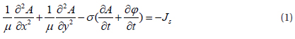
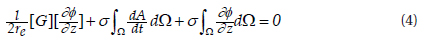
A squirrel cage induction motor has a sufficiently long axial length that can be analyzed two-dimensionally and is well insulated between the stator windings. Assuming that the stator winding or conductor bar currents flow only in the axial direction, modeling was done two-dimensionally. The two-dimensional electromagnetic field governing equation, ignoring the displacement current, is as follows:
Where,
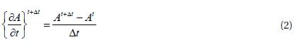
In addition, the time derivative term can be arranged using the backward difference approximation method as follows:
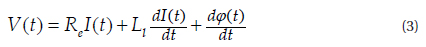
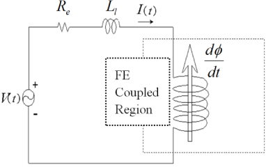
The stator equivalent circuit for a single phase with respect to the stator's windings in induction motors is shown in Fig. 1 Here,

Where
The equivalent circuit in the rotor part consists of the rotor's conductor bar and rotor's end ring. In general, since the gap between the conductor bars is constant and the conductor material is uniform, the resistance of the end ring that connects the conductor bars can be approximated as
Using Kirchhoff's current law, the governing equation for the rotor is
where [
To analyze the dynamic characteristics of inductor motors, a governing equation was set, and it has the following variables: the magnetic vector potential A, the phase currents
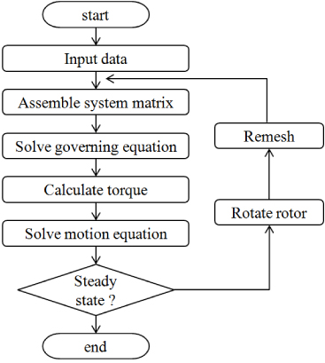
Using Eqs. (1)~(3), simultaneous equations were composed, and a 2D finite element method was applied. Then, the governing equation was solved by applying the Newton-Raphson method in order to take the magnetic saturation in the ferromagnetic material region into consideration.
There are several methods to calculate the torque in motors, but most employ parameters according to the magnetic circuit analysis method. For induction motors, these parameters cannot be calculated accurately because the secondary resistance and magnetizing reactance cannot be defined appropriately.
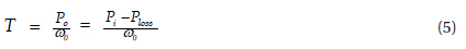
In this section, a motion equation with regard to the rotation of the rotors and an electromagnetic force calculation using the energy input and output relationships are explained. A torque at every moment was calculated using (5) that represents the relationship between the mechanical output and the torque in induction motors. The primary output was set as a value that excludes the loss from the input energy.
In this section, a motion equation with regard to the rotation of the rotors and an electromagnetic force calculation using the energy input and output relationships are explained. A torque at every moment was calculated using (5) that represents the relationship between the mechanical output and the torque in induction motors. The primary output was set as a value that excludes the loss from the input energy.

where
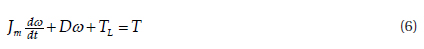
A motion equation has to be used to calculate the rotor's position and velocity at every step when a solution is calculated by a time differential method using the finite element method. The following equation represents the motion equation under such a circumstance:

where
By solving the above differential equation, the position and angular velocity after
In this section, the proposed algorithm was applied to induction motors to analyze the torque for starting and the speed characteristics of the rotors. A 3-phase, 4-pole, and 5-hp squirrel cage induction motor was set as a target to validate the algorithm proposed in this study. The rotation angle and rotation velocity of the rotors and the torque from starting to the steady state of the induction motor were analyzed. In addition, starting characteristics of the induction motor were investigated while changing the slot shapes and materials in the rotor of the induction motor using the analysis algorithm.
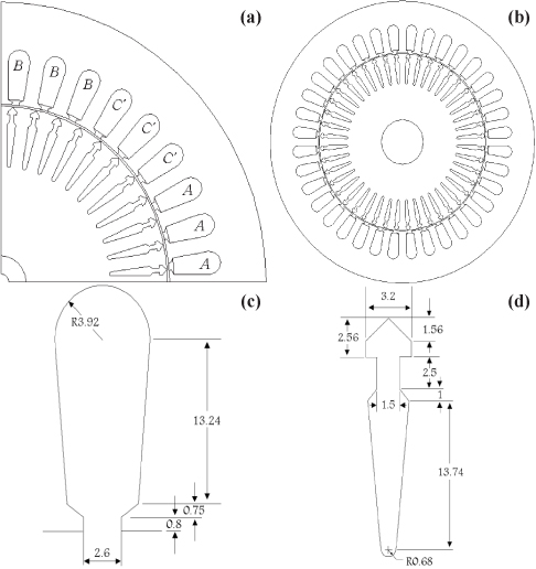
The specifications of the analysis target are listed in Table 1, and Fig. 4 shows a quarter and full shape of the induction motor as well as the slot shapes and dimensions of the stator and rotor. The winding distribution was symmetrical; thus, only a quarter was analyzed. On the basis of the motor characteristics according to the winding arrangement, the boundary conditions at both ends in the analysis model were processed with the antiperiodic boundary condition.
[Table 1.] Details of Analysis Model.
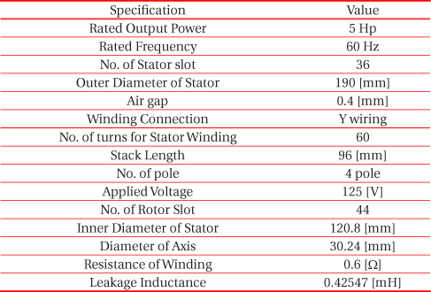
Details of Analysis Model.
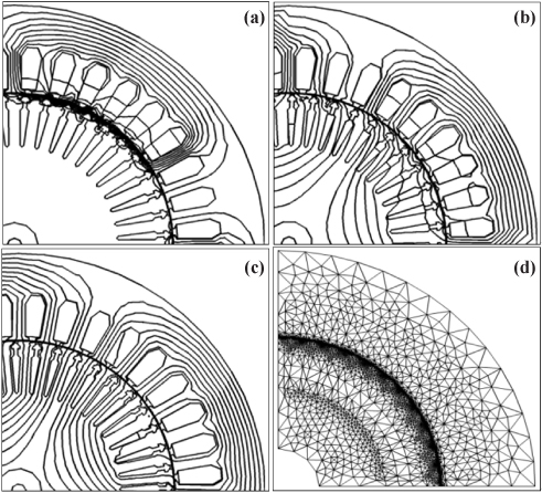
Figure 5 shows the distribution of the magnetic field and the finite element meshes, which are divided by the finite elements of the induction motor according to the slips (velocities).
The dynamic characteristics of the squirrel cage induction motor were compared and presented according to changes in the slot shapes and materials of the rotor. Three shapes were used to present the characteristics according to the changes in the slot shapes of the rotor. Furthermore, three materials-aluminum, copper, and silicon-copper-were selected as the materials of the rotor's slot to investigate the effects of the slot materials on the characteristics of the induction motors.
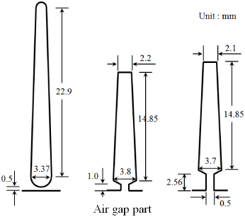
The slot shape of the rotor is shown in Fig. 6 as three shapes for the changes in the slot shapes of the rotor. Figure 6(a) shows the effect of deep slots by making the slot slightly longer to have the same area as that of the existing conductor bar shape. Further, Fig. 6(b) shows the slightly shallow shape of the conductor bar that has the same cross-sectional area as that of the existing shape and the opening of the slot neck of the rotor, which allows for investigation of the characteristics and effects of the shape. Figure 6(c) shows the effect of the slot's neck on the transient characteristics of the induction motor for a neck that is 2.5 times longer for the slot shape. We named the three shapes as Shape 1 for the deep slot, Shape 2 for the shallow slot, and Shape 3 for the long-neck-slot shape.
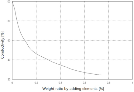
Most squirrel cage induction motors use aluminum whose conductivity is 50~60 [%] as the material of the conductor bars in the rotors. As summarized in Table 2, we performed a simulation with copper whose conductivity is better, and silicon-copper whose conductivity is worse, as the materials of the conductor bar, and the simulation results are shown below. Figure 7 shows the conductivity used conductor bar of the squirrel induction motor [8].
[Table 2.] Electric conductivities of rotor bars.
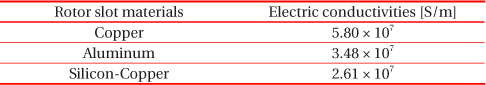
Electric conductivities of rotor bars.
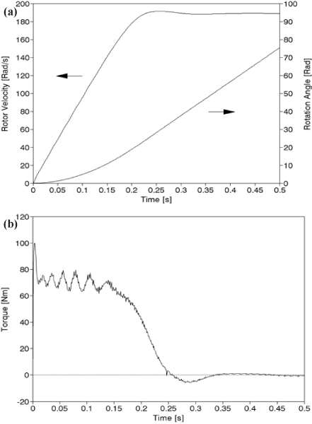
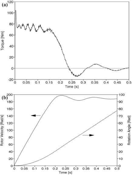
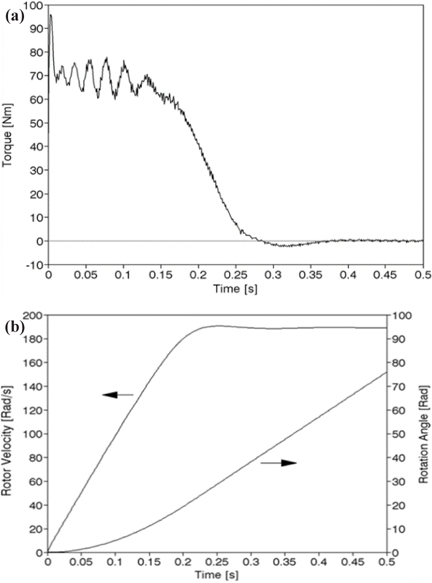
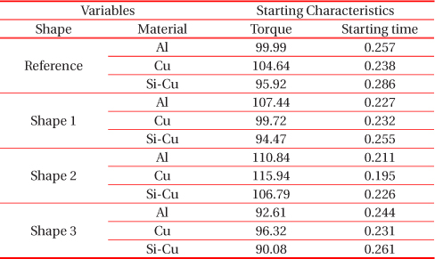
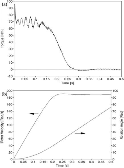
Figures 8, 9, and 10 show the torque and speed characteristic waveforms when the material of the conductor bar is changed to aluminum, copper, and silicon-copper in the reference model shape.
When the material of conductor bar was copper, the current in the starting state was slightly larger, but the current was nearly the same when it was silicon-copper. The starting time was reduced when copper was used, whereas it slightly increased when silicon-copper was used.
Table 3 summarizes the investigation results for the characteristics of the reference model and three different slot shapes by using the proposed algorithm while changing the materials. As shown in the table, when Shape 2 and aluminum and copper were used, the starting torque was the largest, and the starting time was lowest.
[Table 3.] Starting torque and time for various materials and shape of 2nd rotor slot.

Starting torque and time for various materials and shape of 2nd rotor slot.
In this paper, a theory and an algorithm that can determine the dynamic characteristics from starting to the steady state by sequentially combining the electromagnetic field equation and a motion equation were proposed to analyze the starting torque and speed characteristics of squirrel cage induction motors.
When the material of the rotor slot was aluminum and the slot shape was deeper than that reference model, the starting torque slightly increased, and the starting time was minimally decreased. When the slot was shallow, the starting current slightly increased, whereas the starting time was decreased by 18% similar to the deep slot. When the neck was long, both the starting torque and starting time slightly decreased.
When the material of the conductor bar in the reference model was changed to copper, the starting torque was increased more than the target model and slightly reduced the time to reach steady state; however, there was a slight ripple in the early stage of the steady state. When the material of the conductor bar was silicon copper, where silicon was slightly added to copper, the starting torque was smaller than the reference model.