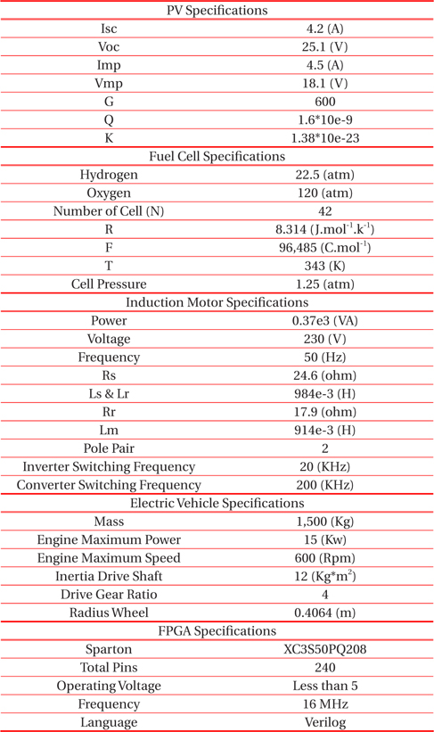
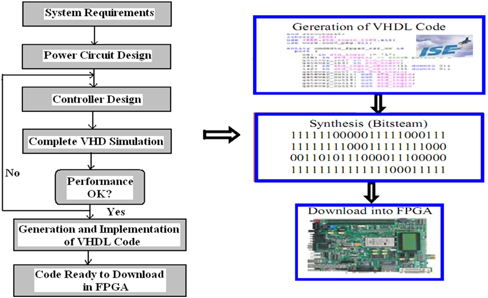
In this study, we present the modern hybrid system based power generation for electric vehicle applications. We describe the hybrid structure of modified current source based DC - DC converters used to extract the maximum power from Photovoltaic (PV) and Fuel Cell system. Due to reduced dc-link capacitor requirement and higher reliability, the current source inverters (CSI) better compared to the voltage source based inverter. The novel control strategy includes Distributed Maximum Power Point Tracking (DMPPT) for photovoltaic (PV) and fuel cell power generation system. The proposed DC - DC converters have been analyzed in both buck and boost mode of operation under duty cycle 0.5>d, 0.5<d<1 and 0.5<d for capable electric vehicle applications. The proposed topology benefits include one common DC-AC inverter that interposes the generated power to supply the charge for the sharing of load in a system of hybrid supply with photovoltaic panels and fuel cell PEM. An improved control of Direct Torque and Flux Control (DTFC) based induction motor fed by current source converters for electric vehicle.In order to achieve better performance in terms of speed, power and miles per gallon for the expert, to accepting high regenerative braking current as well as persistent high dynamics driving performance is required. A simulation model for the hybrid power generation system based electric vehicle has been developed by using MATLAB/Simulink. The Direct Torque and Flux Control (DTFC) is planned using Xilinx ISE software tool in addition to a Modelsim 6.3 software tool that is used for simulation purposes. The FPGA based pulse generation is used to control the induction motor for electric vehicle applications. FPGA has been implemented, in order to verify the minimal error between the simulation results of MATLAB/Simulink and experimental results.
Recently, the research focus on clean and green environment and interest in electrification of existing transportation system are increasing. In order to idle stop the hybrid electric vehicle (HEV ), fuel economy is achieved by using integrated starter generator (ISG). This survey presented three applications of the Z-source inverter (ZSI) for automotive applications. All three structures of Z source inverter supplied by battery to drive an induction motor (IM) for hybrid electric vehicle (HEV) applications and also replace the two stages conversion. These topologies are controlled by using one method on indirect Field Oriented Control (IFOC) for regulation of induction motor speed. The other control strategy uses a proportional plus resonance (PR) controller in the synchronous reference frame to control the ACcurrent for linking the BZSI to the grid throughout the battery charging/discharging mode [1,2].
An improved FPGA based Direct Torque control of induction motor drives fed by converters facilitates very fast responses. Due to DC offset present in the sensed currents, the LP filter is applied for avoiding saturation region. This survey describes the FPGA based on VHDL hardware description language of the design is presented and discussed. The Direct Torque Control design on FPGA is used to compare and verify with simulation design by using MATLAB software. The IFOC control technique is most suitable for controlling an induction motor fed by Z source inverter (ZSI), as compared to other control techniques [3-5]. In this survey, the current-fed switched inverter (CFSI) that combines the high-gain property of ZSI and low passive component count of SBI for both buck and boost modes of operation are explained [6].
Generally, the most efficient combination for power generation such as renewable sources of the hybrid power system consists of PV array and a Proton Exchange Membrane (PEM) fuel cell. The developed control system has been successfully tested in order to verify the functionality of the two renewable sources. Moreover, the autonomous operation cost and reliability of energy has been reduced because the proposed hybrid system requires energy storage for a few seconds. This storage system can inherit the unique advantages of both battery/super capacitor (SC) and the SC/battery HESSs for electric vehicles (EVs). The Capacity of the hybrid system has been increased to a large level by adding increasing numbers of batteries. In this paper hybrid and conventional system together are describe to increase the stability of the system and hence, economical in terms of devices and storing system [7-9]. The power management strategy can be obtained to manage power flows among the different energy sources and the storage unit in the system.The proposed integrated power electronics interface to the PHEVs.It consists of a novel Eight-Switch Inverter (ESI) and an interleaved DC/DC converter. Reduction in cost, size, and achieving the mass of the power electronics unit (PEU) with high performance at any operating mode is required. An improved AC/DC controller based Proportional-Resonant Control (PRC) is purposed in order to reduce the THD of the input current in charger/V2G modes. In this survey the combination of different energy storage system used to achieve a better performance and the concept of hybrid energy storage systems are discussed [10-12].
The multilayer ceramic module of capacitor allows the higher ripple current per unit volume and can help in the miniaturization of bothhybrid and literal electricvehicles. The comparative studies of active bidirectional converter based ISG and passive quasi-Z source inverter (qZSI) based ISG for HEV are reviewed here in. The major design of HEV traction inverters, as compared to different types of the existing inverter topologies for reviewing the power specifications in commercialized hybrid electric vehicles and the advanced power module packaging technology are discussed. The performance Proposal of Potted Inductor materials with various thermal conductivities were investigated for high power boost converter in HEVs [13-16]. The content of this paper deals with modeling of battery, ultracapacitor and the vehicle load for Light electric vehicle applications. Detailed result analyses are carried out for such as capacity of motor, battery and ultra-capacitor for both acceleration and regenerative braking. The different kind of electric motor controls include PI control and sliding mode control (SMC) used for a hybrid electric vehicle based on fuel cell.
Better dynamic performance can be achieved by using SMC as compared to PI controller, when load torque changes at high frequency [17,18].
In this paper, we propose the modified current source based hybrid DC - DC converters for electric vehicle applications. The dynamic modelings of solar array and fuel cell are analyzed for supply to the load separately or simultaneously, depending on the availability of the energy sources. The proposed hybrid structures of DC - DC converters are verified in both buck and boost mode of operation. To extract the maximum power from two different sources, distributed maximum power point tracking (DMPPT) is used. An improved scheme of direct torque and flux control can provide an excellent solution for general purpose IM drives in a very wide power range. Better performance of overall proposed topology has been implemented by using MATLAB/Simulink Simulation tool with FPGA based pulse generation for electric vehicle applications.
2. MODERN HYBRID POWER GENERATION FOR ELECTRIC VEHICLE (EV)
Several hybrid power generation based topologies are developed to realize the Electric Vehicle applications. The hybrid structures of DC - DC converters setup are defined by two electric energy sources of power coupled at a mutual link. However, for the Electric vehicle application, there is a need to reduce the size of all components to be integrated into the system. Generally, most control level is divided into two modes i.e hybrid buck and hybrid boost. These two modes are developed to handle the specificoperating conditions found when the vehicle is operated in the specific mode. Due tothe hybrid operation; the DC-to-DC converter must supplement the generator’s power to the motor drive system. Detailed descriptions of the proposed topology are explained in this section.
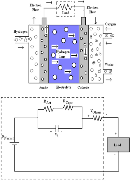
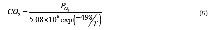
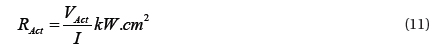
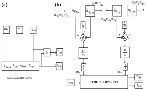
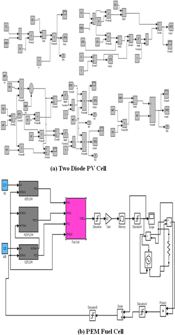
PEM fuel cells combine the hydrogen and oxygen over a platinum catalyst to produce as byproduct of electrochemical energy with water.The variation of the individual output cell voltage is obtained from the maximum cell voltage and the various voltages drops. The basic operation and equivalent electrical circuit of PEM fuel cell is shown below in Fig. 1. The output voltage of single cell can be expressed as,

The reversible voltage of the fuel cell (

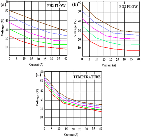
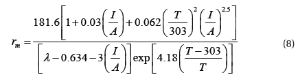
The Polarizations curves of fuel cell generally increase with increasing operating pressure and decrease with decreasing operating pressure. The main reason of this process is that the rate of chemical reaction is proportional to the partial pressureof hydrogen and oxygen. The described characteristic of fuel cell increases with increasing operating temperature. The higher temperature is used to improve mass transfer within the fuel cells and results in net decrease in cell resistance. Thus, the lower current is achieved by highest effect of lower temperature. Moreover, the behavior of PEM fuel under different condition such as hydrogen flow, air flow and operating temperature is shown below in Fig.3. The operating temperatures of PEM fuel cell range from 343 to 383 K.
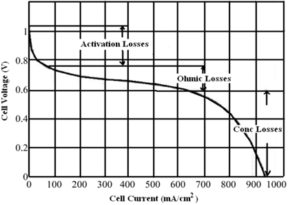
The V-I characteristic of fuel cell shows the different regions and the corresponding polarization effects that are associated with a voltage drop in every region. It can be expressed in the following equation,


The static and dynamic model of fuel cell is shown above in Fig. 4. The effect of double layer charging is mediated by the diffusion and the reaction between the electrons and the ions. This is because of the charge double-layer around the cathode of a fuel cell. If current suddenly changes it means that the operating voltage takes some time to reach its final equilibrium value. The double layer capacitance charging can be obtained by the Equation as follows,
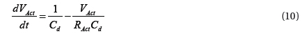

This dynamic model of PEM fuel cell is depicted by the transient’s voltage, cell temperature, hydrogen/oxygen input and output flow rates and cathode/anode channel temperatures and pressures under sudden change in load current. The operating condition of fuel cell is reduced at the higher values of input variables and voltage losses. The overall set of equations is explained to characterize the effects of charge double layer capacitance. It includes the dynamics flow of pressure in the anode and cathode channels for mass/heat transfer transient features in the fuel cell structure.
2.2 Model of Two Diode Photovoltaic (PV) Array
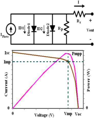
The developed two diode model allows the user to predict a PV cell’s power-voltageand current-voltage characteristics curves by varying cell temperature, sunlight, and ideality factor and series resistance value. The PV model is also applicable under partial shading / module mismatch condition. The more accurate structure of two diode photovoltaic (PV) cell model and I-V & P-V characteristic are shown in Fig. 5.
Based on the above two diode model, the non-ideal PV cell output current can be given as,

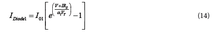
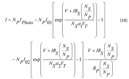
Using physics of p-n junctions, a PV cell could be modeled by a DC current source in parallel with two diodes and the current is getting away due to the diffusion and charge recombination mechanisms. The above equation describes the light generated photo current, shunt current and diode action respectively. This can be expressed as,


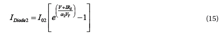

Where, KI is theshort-circuit current temperature coefficient, G is theirradiance, I01 &I02 are the reverse saturation currents, α1&α2 are the ideality factors for the diodes D1 and D2,V is the voltage across the solar cell,VT=KT/q is the thermal voltage and Rs, Rp are the series andshunt resistance respectively. The computation of I01 & I02 can be held by using the open circuit voltage (Voc) and temperature coefficient (Kv). This represent equation can be given as,
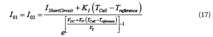
The above expression is used to eliminate the ambiguity in the selection of α1&α2; furthermore, it avoids the iteration process tocompute I01&I02 and simplifies the model by setting I01=I02. The iteration process should start with assuming I=0 and continue until V becomes VOC. In a distinctive large PV power system, the cell modulesare in series-parallel combination (Ns×Np). Here Ns&Np represents the number of cells connected inseries and in parallelrespectively. The modified output current equation can be expressed as,
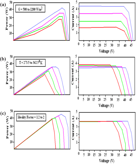
The two diode PV cell characteristics under different condition are shown above in Fig. 6. The I-V and P-V characteristic curves in Fig. 6(a) Represent the effects of the variation of irradiance. These curves show the output current and power increase with increasing irradiance, due to the factthat increase in irradiance increases the light-generated photo current. The effect of the temperature variation depends upon the increase with increasing reverse saturation current. Thus, it becomes the total output power and current decreases, as shown in Fig. 6(b). The variation of the ideality factor increases with decreasing of the reverse saturation current. Thus, the output power and current of a PV cell increase when ideality factor increases, as shown in Fig. 6(c).
2.3 Modified Current Source Based hybrid DC - DC Converters
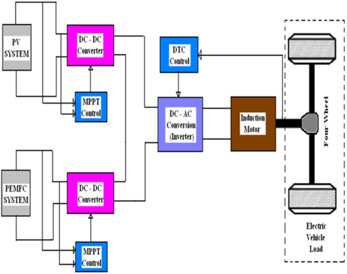
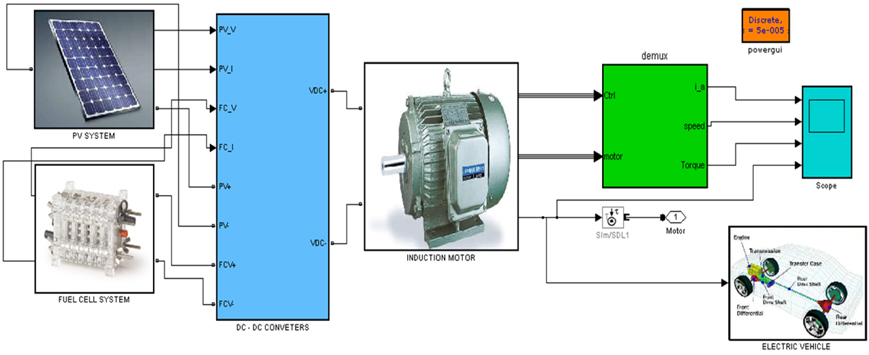
The multiple input converters are essentiallybased on parallel connection at the output of a number ofmodified current fedCuk converters and Buckconverters. The novel system configuration represents the front-end converters stage for hybrid photovoltaic and fuel cell energy sources. The proposed configuration can be applicable for the two sources to supply load separately or simultaneously depending on the availability of the energy sources. Here, the electric vehicle works through a combination of a hybrid structure of DC-DC converter, different kind of renewable energy sources and an electric motor. The overall block diagram of the proposed system configuration is shown below in Fig. 7.
The inherentnature of this Cuk-Buck fused converter is that additional input filters are not necessary tofilter out of the high frequencyharmonics. The hybrid structures of dual input CukBuck converters are applicable for both low and high power generation. Based on the variation of duty cycle, these hybrid converters act on the buck and boost operation.
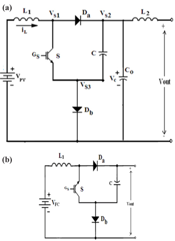
Maximum power is extracted from the renewable sources using the new distributed Maximum Power Point Tracking (DMPPT). The modified current fed Cuk converter is designed by combination of ZSI and Switched Cuk converter shown in Fig. 8(a). Similarly, the current fed Buck converter is designed by combination of ZSI and Switched Buck converter, as shown in Fig. 8(b). The hybrid system configuration allows each converter to operate simultaneously; individually even one source is unavailable. Here, one of the inputs is connected to the output of PV cell and another input is connected to the output of PEM fuel cell. Themodified Perturb and Observe (P&O) Distributed MPPT algorithm is used for extracting maximum power generation from different sources.
To improve the efficiency of the photovoltaic solar panel and PEM fuel cell, DMPPT techniques are used. Consorting to MPPT theorem output power of any circuit can be maximized by adjusting source impedance equal to the load impedance. Because MPPT algorithm is equivalent to the problem of impedance matching. In the present work, the Cuk and Buck Convertersare used as impedance matching device between input and output by changing the duty cycle of the hybrid structure on DC - DC converter circuit. A major advantage of hybrid converter is that high or low voltage is found from the available voltage according to the low and high power application. The overall Output voltage of the DC - DC converter is depends on the duty cycle, so MPPT is used to estimate the duty cycle for receiving the maximum output voltage, since if output voltage increases then power also increases.
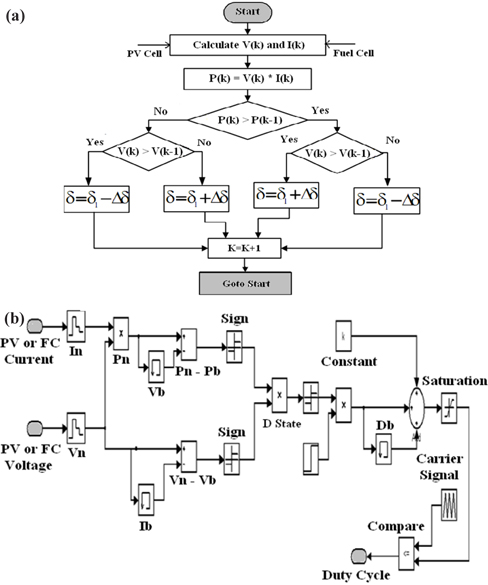
The Fig. 9 above represents the flow chart and Simulink model of Distributed MPPT P&O algorithm. In this flow chart, acting on only voltage is perceived for the purpose of easy implementation. The output power of the system is controlled by varying the supplied voltage. Normally, the switch on period increases the voltage; power also increases, then advance δ is increased, subsequently decreasing the δ period. Similarly, when decreasing voltage if power increases, then the duty cycle is decreased. These steps continue until the maximum power point is reached. The above mentioned corresponding point of voltage, i.e reference voltage is also compared with carrier signal to generate the PWM pulses for DC - DC converters.
3. ENERGY FLOW AND CONTROL SCHEME FOR PROPOSED TOPOLOGY
The term hybrid vehicle denotes a vehicle with at least two sources of power. Here, the hybrid-electric vehicle indicates that two sources of power are provided by an electric motor. These two sources of power can be achieved by the hybrid connection of DC - DC converters. For vehicle in propulsion, energy is available from two or more types of energy sources and at least one of them can deliver electricalenergy. The power sharing configuration of hybrid electric vehicle is shown in Fig.10. The electric motor is used to improve the energy efficiency and vehicular emissions. Generally, there are various possible ways of combining the power flow to meet the electric vehicle driving demands. Here, both power trains I and II for delivery of power to load at the same time could be used. The output load power of an electric vehicle varies randomly in literal operation due to the frequen-tacceleration, deceleration, climbing up and down of gradients.
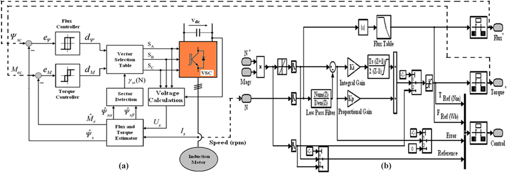
Parallel type of HEV allows both engine and electric motor to deliver the power to drive the four wheels of vehicle. The major advantages of this configuration direct supply torques to the driven wheels and no energy from conversion, so energy loss is less. Also, it provides compactness due to lack of requirement for the generator and smaller traction motor. The control of electric motor obtained by using Direct Torque and Flux Control (DTFC) is shown in Fig. 11.
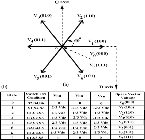
Using Direct torque control in AC motor is possible to obtain a good dynamic torque control without any mechanical transducer on the mechanical shaft. The classical scheme of DTC is preferable in high power applications, because lower inverter switching can justify higher current distortion. The speed controller with Direct flux and torque control block diagram is shown in Fig. 11. The evaluted value of stator flux and electromagnetic torque is compared to the reference i.e., hysteresis controller. The SV - PWM based switching pattern is shown in Fig. 12.
Generally, the six non-zero vectors equally divide the d-q axis into six sectors. The Sectors are numbered by V1 and angle between the two adjacent Sectors is 60 degrees. The above mentioned switching sequence can be used to reduce the loss of switching devices and harmonic component of the output current of the inverter.So that the performance improvements and reduction of torque ripple in transient and steady state response can be achieved.
4. SIMULATION STUDIES AND RESULTS
The hybrid system based DC - DC converters for electric vehicle applications have been implemented by using MATLAB/Simulink Environment. The parameters values used in simulation studies are given in Table 1. The proposed hybrid scheme of converters has been analyzed such as buck and boost mode of operation. The electric vehicle drive train efficiency can be improved with the direct torque control of induction motor. The overall simulink model of proposed topology is shown in Fig.13.
[Table 1.] Parameters of the overall setup.

Parameters of the overall setup.
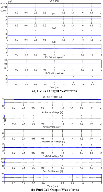
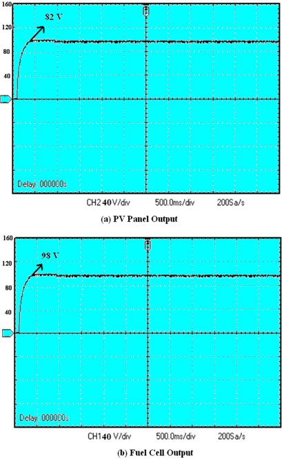
Generally, two kind of unidirectional and bidirectional energy flow are used with DC - DC converters for electric vehicle applications. Moreover, the highest one of them is a high power converter that links to hybrid power train PV panel at a lower voltage with the high voltage DC bus. A second one is a low power converter that links the hybrid power train Fuel Cell with the low voltage DC bus; in order to achieve the buck and boost mode of operations depending upon the variation of converters duty cycle. The detailed model of renewable sources such as Photovoltaic array and PEM fuel cell have been analyzed with output waveforms, as shown in Figs. 14 & 15.
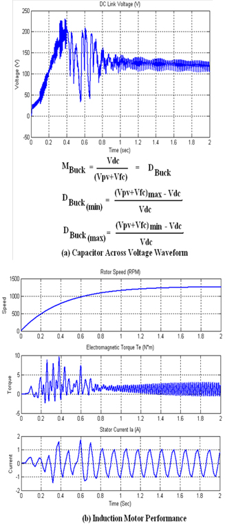
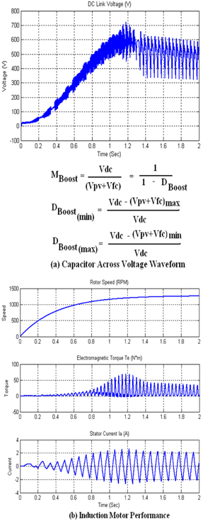
The Direct Torque Control (DTC) is one of the best torque & flux control in steady state and transient state operating conditions of induction motor. The results of DTC gives a fast dynamic response and Space Vector Modulation can be used to improve the flux, torque and current steady state waveforms by ripple reduction. In the present work, a motor drive can be controlled by DTC for electric vehicle and Hybrid electric vehicle (HEV) applications. In overall proposed configuration of topology consider the DC - DC converter with renewable energy directly connected to the inverter and further connected to the induction motor. The buck and boost mode of opeartion can be obtained from this Simulink model for low & high power applications. The operating mode of operation with Simulink results is shown in Figs. 16 & 17.
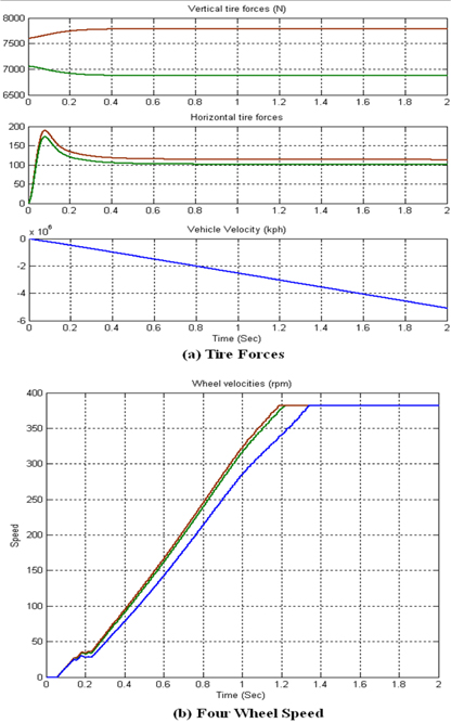
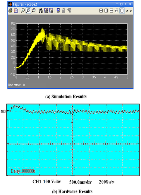
The boost mode of operation in high power is considered for Electric Vehicle Applications. An electric motor capable of producing enough torque to prompt the electric vehicle should be selected. The tractive torque required at the wheels is the product of tractive force and mean effective radius of wheels. The performance of the electric vehicle is shown in Fig. 18.


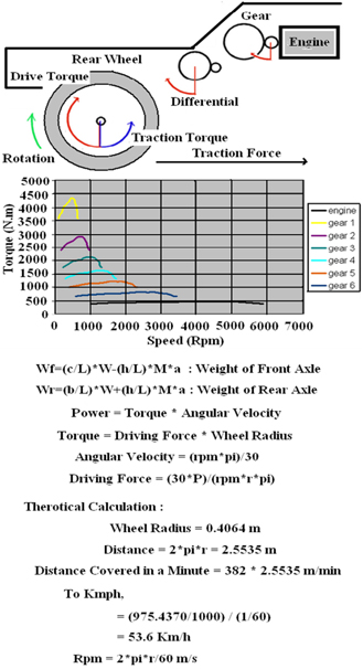
In low gears, the gear ratio is high, so lots of torque is obtained with high speed. In high gears the gear ratio is low, so higher speed is obtained with less torque. In traction, force can be obtained from the addition of tire rolling resistance, forces due to gradient, aerodynamics drag and equivalent inertial force. In order to get the overall transimission efficiency, choosing right size of the motor is required. The tractive torque will be the torque delivered by the engine to that wheel, termed as drive torque. The engine torque is amplified by the gear ratio and the differential ratio. Its provides the drive torque on the rear wheels. The simulation results on electric vehicle performance are shown in Fig.19. The specifications of the overall setup values are provided in Table 1.
5. EXPERIMENTAL STUDIES AND RESULTS
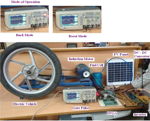
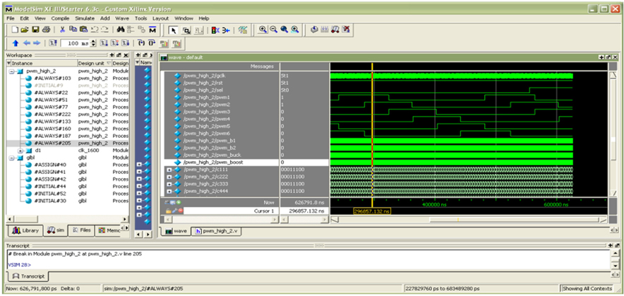
In this section, the specific design measuresuntertaken to further improve the FPGA-based DTC design,hardware units and the experimental setup are presented. FPGA has become one of the mostsuccessful technologies for developing systems that require real time applications.The FPGAs have an additonal advantageof embedded multipliers, which allow faster multiply-accumulate operations. It alsocontains CPU soft core, floating point unit, associated memory subsystems and SPI communication interface. The software used to design the syetm is Xilink Sparton XC3S50PQ208. The design and implementation of controller process is shown in Fig. 20.
Most of this software is mainly used in industries for designing, testing and development of digital ASIC. The process of software system such as design, implementation and simulation. The direct torque control model in MATLAB/Simulink is simulated and the same data used for the simulation are copied from MATLAB workspace to VHDL codes, as the inputs for the targeted FPGA. It is gaining acceptance in high performance power electronics control systems due to the speed, flexibility and integrated design tools. The overall hardware setup of proposed topology is shown in Fig. 21.
The modified current source based hybrid DC DC converters are analysed and verified with hardware setup. It is capable of both low power and high power electric vehicle applications.The induction motor performance have been analysed under buck and boost mode of operation. The FPGA based verilog language is used to generate the gate pulse signals for DC-DC converter and inverter. The hardware results are obtained by the overall setup, as shown in Figs. 22-24.
FPGAs are well-suited for hybrid electric vehicle and EV drive system applications, such as VVC and motor control, due to their parallel architecture and ability to handle multiple complex algorithms simultaneously in hardware. DTFC-SVM has recently been shown to improve torque output and response. SVM is used versus standard PWM because of its benefits, including lower harmonics and switching losses. A modified DTFC-SVM is implemented to eliminate the high-frequency torque and flux ripple due to hysteresis control.
We proposed the modified current source based hybrid DC - DC converter for electric vehicle system. The proposed topology application is expected to improve the vehicle efficiency and reduce production cost due to lower component count, as aone stage converter with a reduced volume, and easiercontrol algorithm. The novel control of Distributed Maximum Power Point Tracking (DMPPT) is used to extract the maximum power under buck and boost mode of operation. It is obtained by the dynamic model of Photovoltaic array and PEM fuel cell for power generation. An improved control strategy utilizing the Direct Torque and Flux Control (DTFC) method is used to control the induction motor speed duringmotoring and regenerative braking operation modes. This directtorque controlspace vector modulation devotes the lower efficiencyand poor ZSI response due to the six shoot through interpolation during SVM. This paper proves the potency of the ZSI, as a single converter with reduced cost due to lower component number, reduced volume, and easier control implementation. It can be used to replace the two stage converter, such as hybrid current source based DC - DC converters. Thus, it will lead to improved vehicle efficiency and reduced production cost. Recently, the FPGA is suitable for high-performance DTC of induction motor drive implementation outstanding to high speed processing. The proposed configuration of the simulation model is analyzed using MATLAB/Simulink software and verified with experimental results from FPGA implementation.