Structural color filters based on nano-photonic structures are regarded as an integral element for the implementation of display devices, image sensors, digital photography and projectors, security tags, color printing, multispectral imaging, and so forth [1-6]. Such structural filters may act as an attractive replacement for conventional colorant pigment-based filters due to their appealing merits in terms of enhanced efficiency, ease of fabrication, and eco-friendliness. Recently, multilayer stacks composed of periodical layers of high (H) and low (L) index layers, particularly received extensive attention as a vehicle to realize structural color filters. Such multilayered structural colors incorporating dense or nano-porous TiO2 and SiO2 were actively studied thanks to their excellent properties, such as high transparency, non-toxicity, chemical stability, good film adhesion, and mechanical durability [7-13].
TiO2 is conspicuously promising from the perspective of its high refractive index (n=~2.3) and good transparency in the visible range. Under the limited availability of low-index materials, multilayered structural colors were actively developed by drawing upon porous or columnar SiO2 or TiO2 as a low-index layer, focusing mainly on the reflection mode while ignoring the transmission color response [7-11]. However, this method suffered from a couple of drawbacks that mostly stem from the porous and/or columnar microstructure of the films. The performance of such devices is potentially vulnerable to the environment, considering that gases or fluids diffusing or penetrating into the device might change the optical properties of the material undesirably [14]. The columnar structure, as in the case of obliquely deposited TiO2 film, renders it optically anisotropic [14]. MgF2, which was widely used for optical coatings in light of its prominent properties in terms of a wide transmission window spanning from UV up to mid-infrared (200 nm ~ 7 μm), high robustness against humidity and mechanical abrasion, is perceived to be an outstanding candidate as a low-index layer associated with BSs with a high index contrast, leading to enhanced reflectivity with a minimal number of pairs [15]. Driven by those advantages, numerous works on TiO2-MgF2 multilayer stacks have been reported for different applications such as bandpass filtering and anti-reflection and high-reflection coatings [16-19]. However, the application of the material combination towards the realization of structural color filters has rarely been discussed. It should also be remarked that the previous reports on multilayered structural colors mostly dealt with their operation in the reflection mode while ignoring the color filtering in transmission-mode [7-13]. A transmission-type color filter is of paramount importance in view of its potential applications in transmissive displays and sensors and thus the investigation of color filtering of such multilayer stacks in both reflection and transmission modes would be highly desirable. By resorting to elevated index contrast between high and low index materials in a multilayer stack, we could acquire enhanced reflectivity while the transmission is significantly suppressed over a spectral range, thereby enabling the development of highly efficient structural trans-reflective colors, which may serve as subtractive and additive color filters in the transmission and reflection mode, respectively. Such trans-reflective color filters are key elements for various optical applications, including holography, CCD imaging, multispectral sensor, and fluorescence microscopy [20, 21]. However, multilayer stacks serving as color filters in such trans-reflective configurations, which require an optimal stop band assuming an appropriate bandwidth within the visible regime, still have not been investigated.
In this paper, we propose and realize highly efficient transreflective color filters operating under normal incidence by exploiting a multilayer stack structure which consists of a stack of five bi-layers of TiO2 and MgF2. We inspect the performance in both transmission and reflection mode in terms of the transmission and reflection efficiencies, chromaticity coordinates, and demonstrated colors. The angular dependence of the transmission/reflection spectra was also meticulously monitored with respect to light polarization. The proposed structural colors, tapping into multilayer stacks incorporating dense multilayers of TiO2 and MgF2, are anticipated to lead to more stable color response compared to porous and columnar counterparts, which are either anisotropic or are potentially vulnerable to the environment, considering that gases or fluids diffusing or penetrating into the device might change the optical properties of the material undesirably [7-11, 14]. The appeal of the work is not only the scope of the material composition that has been utilized for structural color filter applications but also the realization of trans-reflective color filters, featuring an optimal stop band assuming an appropriate bandwidth within the visible regime, which has not been rigorously examined yet.
II. PROPOSED TRANS-REFLECTIVE COLOR FILTER BASED ON A TiO2-MgF2 MULTILAYER STACK
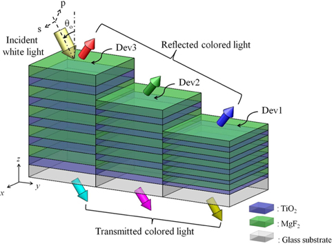
As illustrated in Fig. 1, the proposed color filter capitalizes on a multilayered structure, comprising periodic stacks of alternating layers of high (H) and low (L) index materials of TiO2 and MgF2, respectively. The periodic stack of two materials is supposed to create a photonic band gap where wave propagation is prohibited. Within the corresponding spectral stop band that is centered at a certain wavelength, incident light is remarkably reflected and thus the transmission is suppressed. Hence, the device is anticipated to serve as a structural color filter, delivering red, green, and blue (RGB) color output in the reflection mode and cyan, magenta, and yellow (CMY) color output in the transmission mode. With regard to the structure, the position of the stop band for the normal incidence is determined by m λₒ=2(
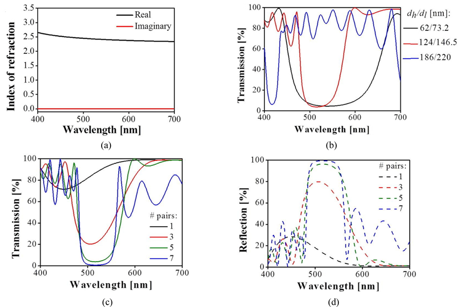
The design of the trans-reflective visible filter was conducted with the assistance of a commercially available tool specialized for analyzing thin-film structures, Essential Macleod (Version 9.8.436). For the numerical simulations, the glass substrate was considered to be semi-infinite while the dispersion properties for deposited TiO2 films were actually taken into account as depicted in Fig. 2(a), while the dispersion for MgF2 films was taken from the refractive index database [22]. The number of TiO2-MgF2 pairs and their thicknesses were varied to attain selectively suppressed transmission spectra and selectively elevated reflection spectra. We first endeavored to examine the effect of
In an effort to probe the influence of the number of TiO2-MgF2 pairs on the optical characteristics of the multilayer structure, we observed the transmission and reflection spectra for the normal incidence. Figures 2(c) and 2(d) respectively illustrate the simulated transmission and reflection spectra for one, three, five and seven pairs within the stack. The thickness of each of the TiO2 and MgF2 layers was uniformly kept at 146.5 nm and 123.9 nm, respectively. As shown in Figs. 2(c) and 2(d), the reflection was selectively enhanced while the transmission was profoundly suppressed around a particular wavelength, when the number of bi-layer pairs was varying from one to seven. However, the off-resonance transmission decreased in the case of seven bi-layers as compared to the case of five bi-layers. This is the reason why we decided to further consider the case of five bi-layers. For a multilayer stack that is made up of five bi-layers or more, the reflection reached as high as 96% and a properly broad reflection peak was observed at λ=518 nm. Similarly, the roll-off characteristics in relation to the transmission dip improved on the whole, with the transmission level held below 4% at the location of the reflection peak. The transmission was over 80% on average over the wavelength range away from the transmission dip. It was readily signified that the proposed device can act as a highly efficient trans-reflective color filter, offering subtractive and additive filtering characteristics in the transmission and reflection modes, respectively.
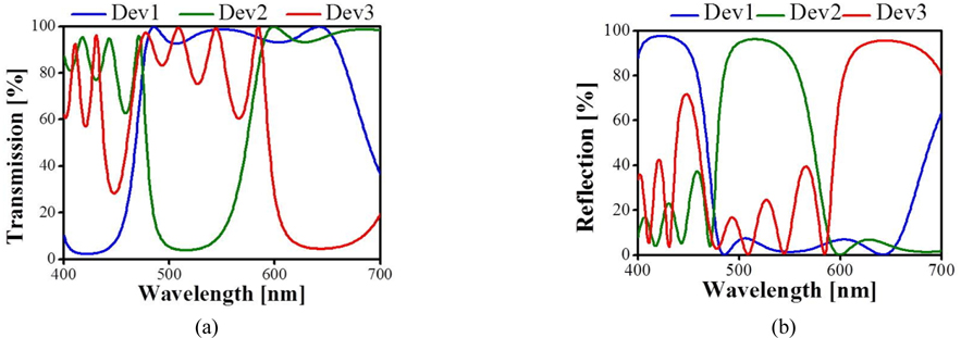
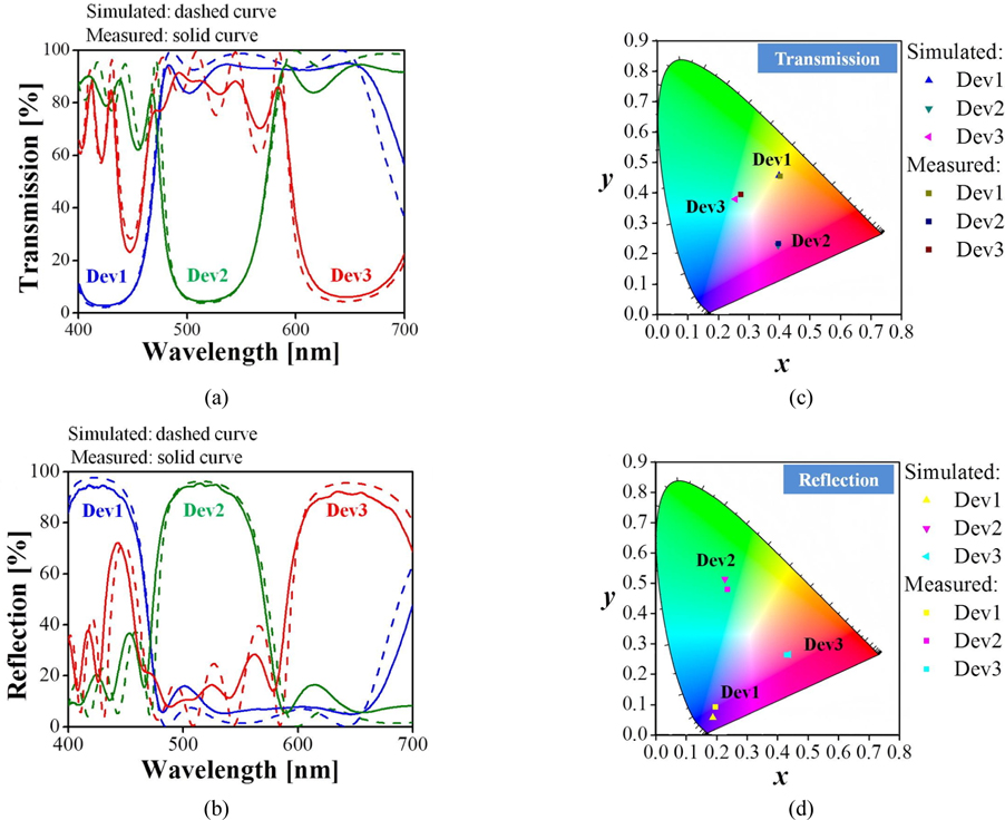
As supported through the additional simulations, the position of the transmission dip and the reflection peak could be tuned across the entire visible band by controlling the thickness of the layers belonging to the stack. Figures 3(a) and 3(b) respectively display the theoretical transmission and reflection spectra of the three devices, designated as Dev1, Dev2, and Dev3, which are composed of five bi-layers with different thicknesses of high- and low-index layers, i.e.
[TABLE 1.] Structural parameters of different multilayer stacks for different resonant wavelengths
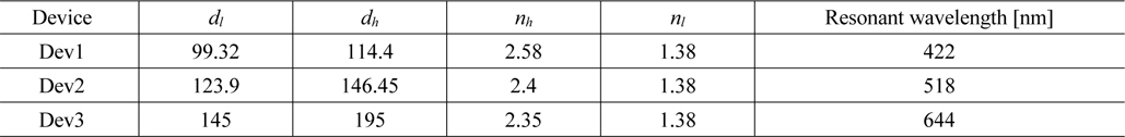
Structural parameters of different multilayer stacks for different resonant wavelengths
III. CONSTRUCTION AND CHARACTERIZATION OF THE TRANS-REFLECTIVE COLOR FILTERS
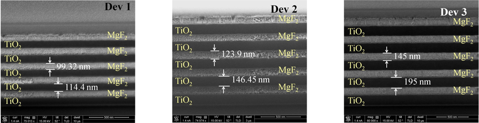
The proposed trans-reflective color filters were fabricated over a footprint of 7.63 × 2.54 cm2 , by forming alternating layers of TiO2 and MgF2 thin films via electron-beam evaporation (Balzers BAK 600). Prior to film deposition, the substrate was ultrasonically cleaned with acetone, isopropanol, and deionized water in sequence. Five TiO2-MgF2 pairs were successively formed on a glass substrate via planetary rotation to obtain uniform films, when the evaporation chamber was evacuated to a base pressure of 6×10⁻⁶ Torr. During TiO2 evaporation a small amount of oxygen with a gas pressure of 5×10⁻⁵ Torr was introduced to make the film composition as stoichiometric as possible; otherwise oxygen-deficit titanium oxide would be obtained. The substrate temperature was kept at 100 ℃ during deposition. The deposition rates for TiO2 and MgF2 films were monitored by a quartz crystal microbalance to keep them at 3 and 39 nm/min, respectively. Figure 4 reveals scanning electron microscopy (SEM) images of the crosssections of the fabricated filters Dev1, Dev2 and Dev3, manifesting clearly defined dielectric layers with good fidelity to design.
In an attempt to evaluate the transmission spectra for the normal and oblique incidence, a collimated light beam from a halogen lamp (Model LS-1, Ocean Optics) was irradiated upon the prepared device mounted on a motorized rotation stage, while the transmitted light was captured by a multimode fiber linked to a spectrometer (Model USB-4000-VIS-NIR, Ocean Optics). Meanwhile, in the course of measuring the reflection spectra, the collimated beam was illuminated on the device via a 50:50 non-polarizing beam splitter cube (BS016, Thorlabs) while the reflected light from the device was deviated by the beam splitter and similarly coupled to a spectrometer. A broadband dielectric mirror with ~99% reflectivity (BB1-E02, Thorlabs) was utilized as a reference for reflection measurements. To investigate the transfer characteristics for different polarizations, the incident light was properly polarized by use of a calcite crystal polarizer (GTH 10M-A, Thorlabs). The transmission and reflection responses were scrutinized under the normal incidence and are presented in Fig. 5, where the measured and calculated spectra are plotted in solid and dashed curves, respectively. As shown in Fig. 5(a), the transmission was found to be selectively suppressed at
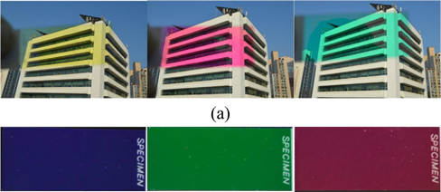
We took a photograph of the color output from fabricated filters, in a bid to prove that the prepared filters are capable of practically demonstrating colors. The photographic images of the three devices including Dev1, Dev2, and Dev3 are displayed from left to right in the transmission mode, as shown in Fig. 6(a), exhibiting bright and distinct colors of yellow, magenta, and cyan, respectively. The corresponding responses in the reflection mode are presented from left to right, as shown in Fig. 6(b), producing bright and vivid colors of blue, green, and red. The filters delivered uniform colors over the developed footprint of 7.63 cm × 2.54 cm both in the transmission and reflection mode. As a result, the fabricated devices were corroborated to act as a highly efficient trans-reflective color filter as intended under normal incidence.
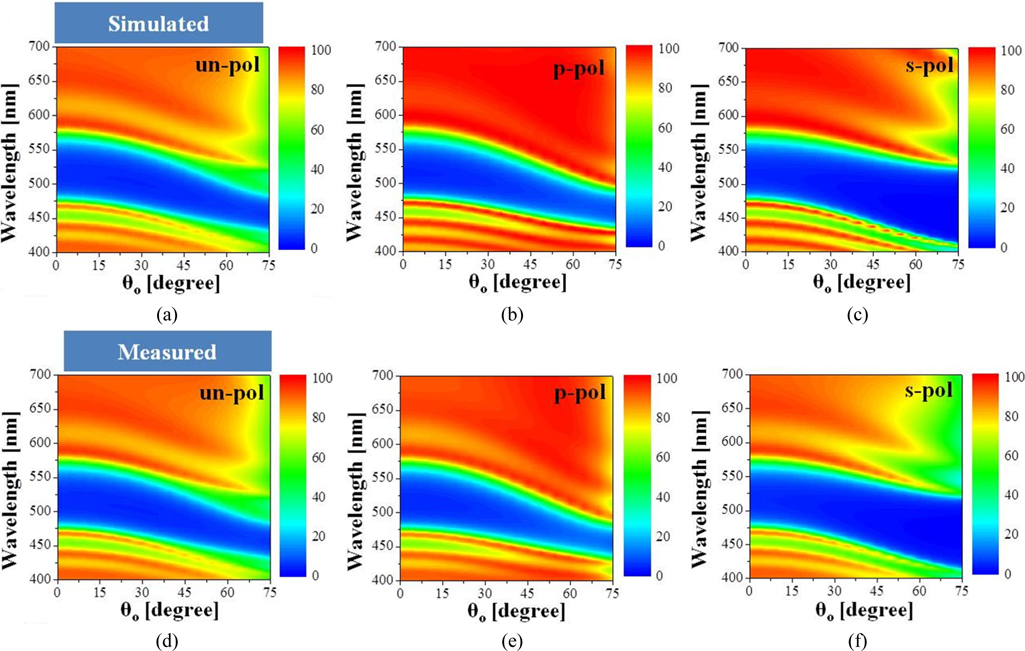
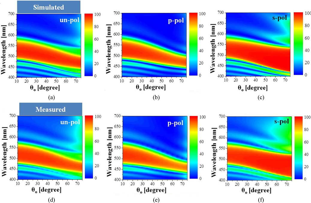
The optical transmission and reflection characteristics of the filters were then explored as a function of the angle of incidence
Finally, we looked into the dependence of the reflection characteristics of the filters upon the angle of incidence
Highly efficient trans-reflective color filters were presented counting on a high index contrast multilayer stack structure constituted of periodically arranged five bi-layers of TiO2 and MgF2 as high and low index materials. The devices featured high efficiencies beyond 90% in both transmissive and reflective configurations, exhibiting vivid primary colors in subtractive as well as additive schemes respectively for those configurations. By adjusting the thicknesses and the numbers of bi-layers, an optimal stop band with an appropriate bandwidth was achieved. The color performance of the filters was scrutinized by referring to the chromaticity coordinates of the transmission and reflection spectra, alongside photographed vivid color images in both modes. The angular dependence and polarization sensitivity were thoroughly assessed for both transmission and reflection spectra. It is definitely predicted that the proposed devices, simply involving deposited bi-layers of TiO2 and MgF2, are conspicuously advantageous in terms of simple and cost-effective fabrication, desirable for scalability and volume production. Inferring from their high efficiency as well as low sensitivity to the angle and polarization, the proposed color filters are categorically predicted to play a pivotal role in display, imaging, and sensor applications.