검색 전체 메뉴
PDF
맨 위로
OA 학술지
Ultrathin Metamaterial for Polarization Independent Perfect Absorption and Band-pass Filter
  • 비영리 CC BY-NC
  • 비영리 CC BY-NC
ABSTRACT
Ultrathin Metamaterial for Polarization Independent Perfect Absorption and Band-pass Filter
KEYWORD
Perfect metamaterial absorber , Band-pass filter , Frequency selective surface , Symmetric split ring resonator
  • I. INTRODUCTION

    Metamaterials are artificial sub-wavelength materials manufactured to exhibit extraordinary electromagnetic properties such as negative refraction [1, 2], enhanced antennas [3, 4], electromagnetic cloaking [5], super-resolution [6, 7], band-pass filter [8], etc. Among the applications of metamaterials, the concept of MA has attracted considerable attention owing to its crucial importance for civilian and military applications during the last few years.

    The first MA was demonstrated by Landy et al. using metamaterials in the GHz regime [9]. By tuning the electric and magnetic responses and the impedance z (ω) of metamaterials, a near unity absorption peak can be realized theoretically and experimentally at the resonant frequency. Since the first reported MA, various kinds of perfect metamaterial absorbers (MAs) have been developed to achieve the goals: multiband [10-18], wide band [19-24], and independent of polarization and the incident angle of electromagnetic waves [14-18, 23-28].

    The physical mechanism of the MAs can be explained with the effective medium theory. The effective material parameters include effective relative permittivity ε(ω) = ε′(ω) + iε ′′(ω ), and effective relative permeability µ(ω ) = µ′(ω ) + iµ′′(ω ), which are variables of frequency of the incident electromagnetic wave. By adjusting the structure parameters of metamaterial, the real and imaginary parts of the effective material parameters can be controlled separately. In order to realize a perfect absorber, the impedance (defined as of the metamaterial structure should be equal to the impedance of vacuum (free space) for zero/nearly zero reflection. The transmission will also be zero since the metal ground plane thickness used in conventional MAs is greater than the skin depth in this frequency range [10-30]. In the case without reflection and transmission simultaneously, total absorption will occur within a certain frequency band. However the electromagnetic waves with frequency higher than the absorption band are difficult to pass through the MA due to the skin effect, and the band-pass properties out of the working band of MAs are always important for practical applications, e.g., for communications.

    The frequency selective surface (FSS) is a one- or two- dimensional periodic assembly of conducting patches on dielectric sheets or apertures in a thin conducting sheet which may have the property of band-stop or band-pass, respectively [31]. In our work we propose an MA design with the metallic background plane in conventional MAs replaced by a SGP which is a conducting sheet with a periodic hole array. The SGP which is actually a FSS in our design also provides the band-pass functionality in the newly designed MA.

    In this paper, we first designed a polarization dependent MA based on SGP and symmetric split ring resonator (SSRR) [32]. The absorption is more than 93.7% centered at the frequency of 31.18 GHz. Then we designed a polarization independent MA through rearrangement of the SSRRs. The absorption is more than 94.3% centered at about 32 GHz, and more interestingly, a pass band with a transmission of about 42% centered at 46.40 GHz was observed from the simulation results.

    II. POLARIZATION DEPENDENT PERFECT METAMATERIAL ABSORBER

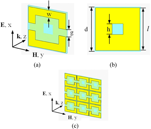
    In our work, a single unit cell of the polarization dependent MA consists of two distinct metallic elements (shown in Fig. 1(a)). The array of metal SSRR with two gaps is on the front layer of a dielectric substrate (blue part in Fig. 1(a)) and a metal SGP is on the back layer (shown in Fig. 1(b)).

    As to the incident electromagnetic wave with electric component parallel to the split direction of the SSRR (x direction in Fig. 1(a)), the SSRR can couple strongly to it, thus supplying an independent electric response. The magnetic component of the incident wave will penetrate the front layer. Since the magnetic component is along the y direction (shown in Fig. 1(a)), it will generate anti-parallel surface currents on the SSRR and SGP along the x direction, which is the magnetic coupling and resonance. Then high electromagnetic losses from the electric and/or magnetic resonances will be introduced similar to the physical mechanism used in Ref. [9]. In order to make the wave impedance of the MA matched to that of free space, the dimensions of the SSRR should be adjusted.

    We select FR-4 (lossy) with the relative dielectric constant εr = 4.3 and the loss tanδ = 0.025 as the dielectric substrate. The side length of the FR-4 dielectric plate is d = 6.3 mm, and the thickness is 0.3 mm. The SSRR and SGP are copper with conductivity σ = 5.96×10⁷ S/m and thickness 0.017 mm. The optimal parameters for the MA unit cell are as follows (in millimeters): g = w = 1.1, h = 1.5 and l = 6.

    A numerical simulation is performed for the polarization dependent MA shown in Fig. 1(a) based on the finite element method. Periodic boundary conditions are used in the x and y directions (shown in Fig. 1(c)). For the MA, the expression of the absorption is A(ω ) = 1-T(ω )-R(ω ) = 1-|S21|2 − |S11|2, in which T(ω) = |S21|2 and R(ω) = |S11|2· A(ω ), T(ω ), and R(ω ) are the absorption, transmission and reflection coefficients, respectively.

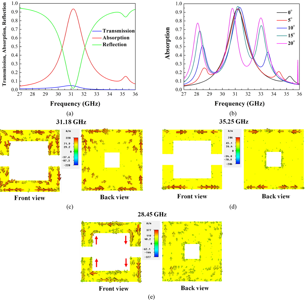
    As shown in Fig. 2(a), the maximum absorption is about 93.7% centered at 31.18 GHz for the normal incident electromagnetic wave. When the incident angle increases from 0° to 15°, the maximum absorption frequency of the MA is centered at 31.18 GHz with almost no change (shown in Fig. 2(b)) and the maximum absorption increases from 93.7% to 96.7% with other absorption peaks created simultaneously. There is a high-frequency absorption band and a low-frequency absorption band besides the main absorption band. The main absorption band will have a red shift when the incident angle is greater than 15° (see the result when the incident angle is 20°).

    To have a deep understanding of the nature of the absorption bands, the simulated surface current distributions of the three absorption bands are presented in Figs. 2(c)-(e). As shown in Fig. 2(c), the anti-parallel currents at the front SSRR and back SGP at 31.18 GHz indicate that the main absorption band for the normal incidence is induced by the magnetic resonance. From the surface current distributions (not shown here), the main absorption bands for the incident angles of 5°-20° are also induced by the magnetic resonance. The distribution of surface current at the high-frequency absorption peak (at 35.25 GHz) for the normal incidence is shown in Fig. 2(d). The strong parallel currents at the edges of the front SSRR and back SGP indicate that the high-frequency absorption bands for the normal incidence and non-normal incidence (not shown here) are induced by the electric resonance.

    With the increase of the incident angle, the magnetic field will have component parallel to the direction of the z axis which will affect the distribution of the surface currents in the structure. Then another new mode of resonance will occur. The 10° incidence is taken as an example to illustrate this phenomenon shown in Fig. 2(e). The z direction component of the magnetic field generates a current circle, which is marked by the red arrows in Fig. 2(e). This new mode of low-frequency resonance with a frequency of 28.45 GHz for 10° incidence and those for other non-normal incidences (not shown here) are also magnetic resonances from the surface current distributions.

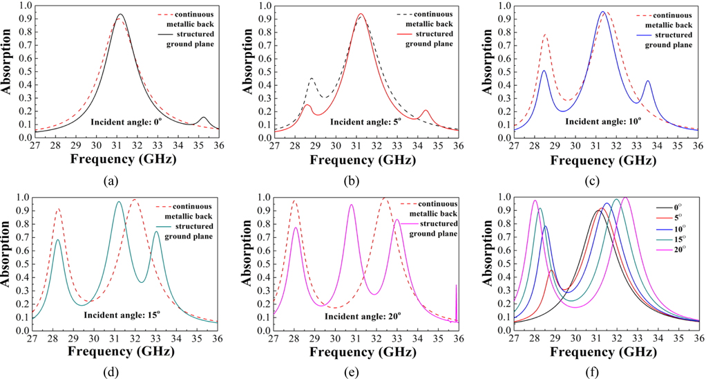
    In order to find the difference between the newly designed MA and the conventional MA, the SGP used in our design is replaced by a continuous metallic back to form the conventional MA. When the incident angle increases from 0° to 20°, the absorption comparisons between the newly designed MA and the conventional MA are shown in Figs. 3(a)-(e). Our newly designed MA has almost the same absorption band and absorption intensity as the conventional MA for the normal incident electromagnetic wave. However, the maximum absorption band of the newly designed MA has little change when the incident angle is lower than 15° as mentioned above. While the maximum absorption band of the conventional MA will shift with the increase of the incident angle (shown in Fig. 3(f)).

    III. POLARIZATION INDEPENDENT PERFECT METAMATERIAL ABSORBER AND BAND-PASS FILTER

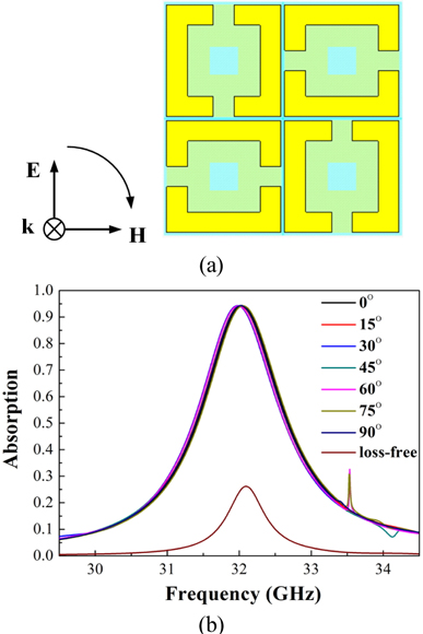
    A single SSRR is a polarization dependent resonant structure from the above analysis due to the nonsymmetric nature of the SSRR both in the x and y directions of the unit cell. In the following, a polarization independent absorber is constructed and analyzed. Two sets of SSRRs are employed with orthogonal orientations in the unit cell to construct a polarization independent MA shown in Fig. 4(a). The structure has the same parameters with the polarization dependent MA shown in Fig. 1.

    From Fig. 4(b) we can see that the electromagnetic waves are perfectly absorbed in the same band for polarization angles ranging from 0° to 90° due to the symmetry of the designed polarization independent MA. For example, the maximum absorption is 94.3% at 32.04 GHz for the polarization angle of 0°, and the maximum absorption is 94.3% at 32.02 GHz for the polarization angle of 90°. The full width at half maximum (FWHM) of the absorption band is about 1.33 GHz. And the total thickness of the unit cell is only about 1/28 of the maximum absorption wavelength.

    In Section II the maximum absorption is about 93.7% centered at 31.18 GHz in Fig. 2(a), while it reaches 94. 3% centered at 32.04 GHz in Fig. 4(b) for the normal incident electromagnetic wave with polarization angle of 0°. The shift of the absorption frequency should be caused by the change in the arrangement of the SSRRs.

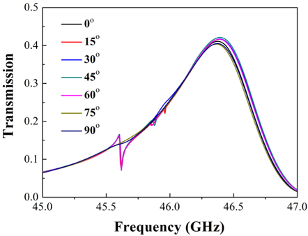
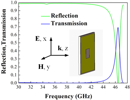
    As shown in Fig. 5, a transmission band centered at 46.40 GHz for the normal incident electromagnetic waves can also be found for the polarization independent MA. The maximum transmission is about 42% with a FWHM of 0.79 GHz independent of the polarization angles. To explain the band-pass features, the reflection and transmission of the SGP used in the unit cell with an FR-4 dielectric substrate of thickness 0.3 mm are calculated for the electromagnetic wave with polarization angle of 0° (shown in Fig. 6). As shown in Fig. 6, simulation shows that a wave band centered at 46.46 GHz can pass though the structure with a transmission of 69.1%, leading to the bandpass property of the polarization independent MA and BPF. As to the electromagnetic wave with frequency of 32.04 GHz, the SGP served as a complete reflector similar to the metal ground plane used in conventional MAs.

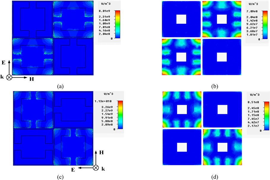
    To obtain insight into the physical mechanism of the absorbing property of the polarization independent MA, the power loss density distributions at frequencies of 32.04 GHz and 32.02 GHz for polarization angles of 0° and 90° are also calculated, respectively, and the results are shown in Fig. 7. It is seen that the resonances will occur when the electric components of the incident waves are parallel to the split directions of the SSRRs.

    From the simulation results shown in Fig. 7, the maximum dielectric loss density (shown in Figs. 7 (a), (c)) is an order of magnitude greater than that of the Ohmic loss (shown in Figs. 7(b), (d)) at frequencies of 32.04 and 32.02 GHz, respectively. Fig. 4(b) also shows the absorption spectra when the dielectric layer is loss-free. The maximum absorption caused by the Ohmic losses is only 26.2% which is much less compared with the value (68.1%) caused by the dielectric losses. The result is in accordance with studies of MAs where it was found that Ohmic losses were relatively insignificant compared with dielectric losses as to the metamaterial-based perfect absorbers when the thickness of the copper used in the MAs is on the order of µm [33, 34]. From Figs. 7(a), (c) we can also see that the MA concentrates the electromagnetic waves in the dielectric area covered by the SSRRs, where electromagnetic energy is converted into thermal energy, leading to the strong dielectric losses.

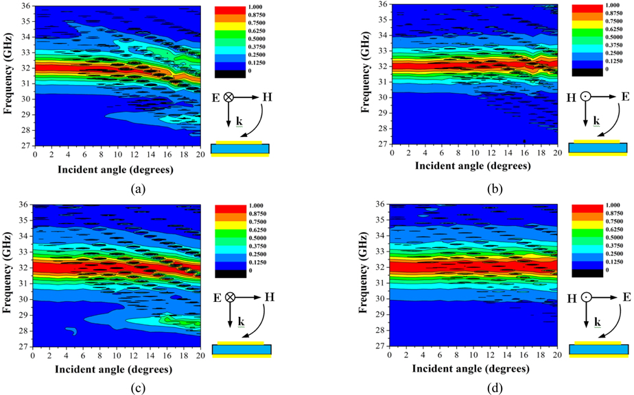
    The newly designed polarization independent MA can also be used for non-normal incidence, in which electromagnetic waves both in the transverse-electric (TE) and transverse-magnetic (TM) modes are taken as an example. As shown in Fig. 8(a) the absorption of the TE mode is nearly independent of the incident angles below 10°. As the incident angle increases further, a red shift of the absorption band will occur. For TM mode, the absorption is nearly independent of the incident angles below 20° (shown in Fig. 8(b)). Figs. 8(c) and 8(d) show the absorption bands of the polarization independent MA when the SGP is replaced by a continuous metallic back (to construct the conventional MA). Our newly designed MA has almost the same absorption band and absorption intensity as the conventional MA for both TE and TM modes. But the absorption bands become a little narrower compared with the conventional MA. However, when the incident angle is lower than 10° there are fewer dark areas in the central absorption bands of the newly designed MA than for the conventional MA for both TE and TM modes.

    IV. CONCLUSION

    In the present work, an ultrathin polarization independent MA based on SSRRs and SGP is investigated theoretically. This newly designed MA is not limited to the minimum thickness of a quarter wavelength, with a whole thickness of only 0.334 mm (about 1/28 of the maximum absorption wavelength). The proposed MA provides perfect absorption and polarization-incident angle independency in the microwave Ka frequency band (centered at about 32 GHz) while the reflection is minimized. From comparative investigations between our newly designed MA and a conventional MA, the absorption band and absorption intensity are almost the same. However, the absorption of our newly designed MA has better performance than that of the conventional MA when the incident angle is lower than 10°.

    In our new design, the continuous metallic back which served as a complete reflector in conventional MAs has been replaced by a metallic SGP. Since the SGP used in the design has the property of band-pass, a transmission band centered at 46.40 GHz can be obtained. This structure can be used to prevent the electromagnetic interference in communications and provides a new way to design the MA.

참고문헌
  • 1. Veselago V. G. (1968) “The electrodynamics of substances with simultaneously negative values of ε and μ,” [Sov. Phys. Usp.] Vol.10 P.509-514 google cross ref
  • 2. Shelby R. A., Smith D. R., Schultz S. (2001) “Experimental verification of a negative index of refraction,” [Science] Vol.292 P.77-79 google cross ref
  • 3. Zhou B., Li H., Zou X. Y., Cui T. J. (2011) “Broadband and high-gain planar vivaldi antennas based on inhomogeneous anisotropic zero-index metamaterials,” [Prog. Electromagn. Res.] Vol.120 P.235-247 google cross ref
  • 4. Zarifi D., Oraizi H., Soleimani M. (2012) “Improved performance of circularly polarized antenna using semi-planar chiral metamaterial covers,” [Prog. Electromagn. Res.] Vol.123 P.337-354 google cross ref
  • 5. Schurig D., Mock J. J., Justice B. J., Cummer S. A., Pendry J. B., Starr A. F., Smith D. R. (2006) “Metamaterial electromagnetic cloak at microwave frequencies,” [Science] Vol.314 P.977-980 google cross ref
  • 6. Pendry J. B. (2000) “Negative refraction makes a perfect lens,” [Phys. Rev. Lett.] Vol.85 P.3966-3969 google cross ref
  • 7. Xie Y., Jiang J., He S. (2012) “Proposal of cylindrical rolled-up metamaterial lenses for magnetic resonance imaging application and preliminary experimental demonstration,” [Prog. Electromagn. Res.] Vol.124 P.151-162 google cross ref
  • 8. Lee C. M., Shim W. S., Moon Y., Seo C. H. (2012) “Design of ultra-wide band-pass filter based on metamaterials applicable to microwave photonics,” [J. Opt. Soc. Korea] Vol.16 P.288-291 google cross ref
  • 9. Landy N. I., Sajuyigbe S., Mock J. J., Smith D. R., Padilla W. J. (2008) “Perfect metamaterial absorber,” [Phys. Rev. Lett.] Vol.100 P.207402 google cross ref
  • 10. Ma Y., Chen Q., Grant J., Saha S. C., Khalid A., Cumming D. R. S. (2011) “A terahertz polarization insensitive dual band metamaterial absorber,” [Opt. Lett.] Vol.36 P.945-947 google cross ref
  • 11. Yoo Y. J., Kim Y. J., Tuong P. V., Rhee J. Y., Kim K. W., Jang W. H., Kim Y. H., Cheong H., Lee Y. P. (2013) “Polarization-independent dual-band perfect absorber utilizing multiple magnetic resonances,” [Opt. Express] Vol.21 P.32484-32490 google cross ref
  • 12. Tuong P. V., Park J. W., Rhee J. Y., Kim K. W., Jang W. H., Cheong H., Lee Y. P. (2013) “Polarization-insensitive and polarization-controlled dual-band absorption in metamaterials,” [Appl. Phys. Lett.] Vol.102 P.081122 google cross ref
  • 13. Yoo Y. J., Kim Y. J., Hwang J. S., Rhee J. Y., Kim K. W., Kim Y. H., Cheong H., Chen L. Y., Lee Y. P. (2015) “Triple-band perfect metamaterial absorption, based on single cut-wire bar,” [Appl. Phys. Lett.] Vol.106 P.071105 google cross ref
  • 14. Tao H., Bingham C., M., Strikwerda A. C., Pilon D., Shrekenhamer D., Landy N. I., Fan K., Zhang X., Padilla W. J., Averitt R. D. (2008) “Highly flexible wide angle of incidence terahertz metamaterial absorber: Design, fabrication, and characterization,” [Phys. Rev.] Vol.78 P.241103 google cross ref
  • 15. Shen X. P., Cui T. J., Zhao J. M., Ma H. F., Jiang W. X., Li H. (2011) “Polarization-independent wide-angle triple-band metamaterial absorber,” [Opt. Express] Vol.19 P.9401-9407 google cross ref
  • 16. Shen X. P., Yang Y., Zang Y. Z., Gu J. Q., Han J. G., Zhang W. L., Cui T. J. (2012) “Triple-band terahertz metamaterial absorber: Design, experiment, and physical interpretation,” [Appl. Phys. Lett.] Vol.101 P.154102 google cross ref
  • 17. Bian B. R., Liu S. B., Wang S. Y., Kong X. K., Zhang H. F., Ma B., Yang H. (2013) “Novel triple-band polarizationinsensitive wide-angle ultra-thin microwave metamaterial absorber,” [J. Appl. Phys.] Vol.114 P.194511 google cross ref
  • 18. Park J. W., Tuong P. V., Rhee J. Y., Kim K. W., Jang W. H., Choi E. H., Chen L. Y., Lee Y. P. (2013) “Multi-band metamaterial absorber based on the arrangement of donuttype resonators,” [Opt. Express] Vol.21 P.9691-9702 google cross ref
  • 19. Cui Y. X., Xu J., Fung K., H., Jin Y., Kumar A., He S. L., Fang N. X. (2011) “A thin film broadband absorber based on multi-sized nanoantennas,” [Appl. Phys. Lett.] Vol.99 P.253101 google cross ref
  • 20. Ding F., Cui Y. X., Ge X. C., Jin Y., He S. L. (2012) “Ultra-broadband microwave metamaterial absorber,” [Appl. Phys. Lett.] Vol.100 P.103506 google cross ref
  • 21. Hao J. P., Lheurette E., Burgnies L., Okada E., Lippens D. (2014) “Bandwidth enhancement in disordered metamaterial absorbers,” [Appl. Phys. Lett.] Vol.105 P.081102 google cross ref
  • 22. Dung N. V., Tuong P. V., Yoo Y. J., Kim Y. J., Tung B. S., Lam V. D., Rhee J. Y., Kim K. W., Kim Y. H., Chen L. Y., Lee Y. P. (2015) “Perfect and broad absorption by the active control of electric resonance in metamaterial,” [J. Opt.] Vol.17 P.045105 google cross ref
  • 23. Viet D. T., Hien N. T., Tuong P. V., Minh N. Q, Trang P. T., Le L. N., Lee Y. P., Lam V. D. (2014) “Perfect absorber metamaterials: Peak, multi-peak and broadband absorption,” [Opt. Commun.] Vol.322 P.209-213 google cross ref
  • 24. Aydin K., Ferry V. E., Briggs R. M., Atwater H. A. (2011) “Broadband polarization-independent resonant light absorption using ultrathin plasmonic super absorbers,” [Nat. Commun.] Vol.2 P.517 google cross ref
  • 25. Huang Y. J., Wen G. J., Li J., Zhu W. R., Wang P., Sun Y. H. (2013) “Wide-angle and polarization independent metamaterial absorber based on snowflake-shaped configuration,” [J. Electromagnetic Waves and Applications] Vol.27 P.552-559 google cross ref
  • 26. Sabah C., Dincer F., Karaaslan M., Unal E., Akgol O., Demirel E. (2014) “Perfect metamaterial absorber with polarization and incident angle independencies based on ring and crosswire resonators for shielding and a sensor application,” [Opt. Commun.] Vol.322 P.137-142 google cross ref
  • 27. Dincer F., Karaaslan M., Unal E., Akgol O., Demirel E., Sabah C. (2014) “Polarization and angle independent perfect metamaterial absorber based on discontinuous cross-wire-strips,” [J. Electromagnetic Waves and Applications] Vol.28 P.741-751 google cross ref
  • 28. Zhu B., Feng Y. J., Zhao J. M., Huang C., Jiang T. (2010) “Switchable metamaterial reflector/absorber for different polarized electromagnetic waves,” [Appl. Phys. Lett.] Vol.97 P.051906 google cross ref
  • 29. Yuan H., Zhu B. O., Feng Y. (2015) “A frequency and bandwidth tunable metamaterial absorber in x-band,” [J. Appl. Phys.] Vol.117 P.173103 google cross ref
  • 30. Yoo Y. J., Zheng H. Y., Kim Y. J., Rhee J. Y., Kang J.-H., Kim K. W., Cheong H., Kim Y. H., Lee Y. P. (2014) “Flexible and elastic metamaterial absorber for low frequency, based on small-size unit cell,” [Appl. Phys. Lett.] Vol.105 P.041902 google cross ref
  • 31. Munk B. A. 2000 Frequency Selective Surfaces Theory and Design google
  • 32. Lam V. D., Kim J. B., Lee S. J., Lee Y. P. (2008) “Electromagnetic behavior of representative metamaterial structures,” [J. Korean Phys. Soc.] Vol.53 P.558-563 google cross ref
  • 33. Tuong P. V., Park J. W., Lam V. D., Jang W. H., Nikitov S. A., Lee Y. P. (2013) “Dielectric and Ohmic losses in perfectly absorbing metamaterials,” [Opt. Commun.] Vol.295 P.17-20 google cross ref
  • 34. Rhee J. Y., Yoo Y. J., Kim K. W., Kim Y. J., Lee Y. P. (2014) “Metamaterial-based perfect absorbers,” [J. Electromagnetic .Waves and Applications] Vol.28 P.1541-1580 google cross ref
OAK XML 통계
이미지 / 테이블
  • [ FIG. 1. ]  Schematic diagram of the polarization dependent MA: (a) Front view of the unit cell. (b) Back view of the unit cell. (c) 3×3 unit cells.
    Schematic diagram of the polarization dependent MA: (a) Front view of the unit cell. (b) Back view of the unit cell. (c) 3×3 unit cells.
  • [ FIG. 2. ]  (a) Transmission, absorption and reflection of the polarization dependent MA for the normal incident electromagnetic wave. (b) Absorption properties of the polarization dependent MA when the incident angle increases from 0° to 20°. Distributions of induced surface current of the three absorption bands: (c) main absorption band for 0° incidence, (d) high-frequency absorption band for 0° incidence, (e) low-frequency absorption band for 10° incidence.
    (a) Transmission, absorption and reflection of the polarization dependent MA for the normal incident electromagnetic wave. (b) Absorption properties of the polarization dependent MA when the incident angle increases from 0° to 20°. Distributions of induced surface current of the three absorption bands: (c) main absorption band for 0° incidence, (d) high-frequency absorption band for 0° incidence, (e) low-frequency absorption band for 10° incidence.
  • [ FIG. 3. ]  The absorption comparisons between the newly designed polarization dependent MA and the conventional MA when the incident angle increases from 0° to 20°: (a) 0°, (b) 5°, (c) 10°, (d) 15°, (e) 20°. (f) Absorption properties of the polarization dependent conventional MA when the incident angle increases from 0° to 20°.
    The absorption comparisons between the newly designed polarization dependent MA and the conventional MA when the incident angle increases from 0° to 20°: (a) 0°, (b) 5°, (c) 10°, (d) 15°, (e) 20°. (f) Absorption properties of the polarization dependent conventional MA when the incident angle increases from 0° to 20°.
  • [ FIG. 4. ]  (a) Schematic diagram of the polarization independent MA unit cell. (b) Absorption characteristics of the polarization independent MA at different incidences of polarization angles ranging from 0° to 90° and the absorption characteristics when the dielectric layer is loss-free.
    (a) Schematic diagram of the polarization independent MA unit cell. (b) Absorption characteristics of the polarization independent MA at different incidences of polarization angles ranging from 0° to 90° and the absorption characteristics when the dielectric layer is loss-free.
  • [ FIG. 5. ]  Transmission of the polarization independent MA and BPF for the normal incident electromagnetic waves with polarization angles ranging from 0° to 90°.
    Transmission of the polarization independent MA and BPF for the normal incident electromagnetic waves with polarization angles ranging from 0° to 90°.
  • [ FIG. 6. ]  Reflection and transmission of the SGP as to the normal incident electromagnetic wave with polarization angle of 0°.
    Reflection and transmission of the SGP as to the normal incident electromagnetic wave with polarization angle of 0°.
  • [ FIG. 7. ]  Simulated power loss density distributions for the polarization independent MA. Power loss density at 32.04 GHz for the polarization angle of 0°: (a) the dielectric loss, (b) the Ohmic loss of SGP. Power loss density at 32.02 GHz for the polarization angle of 90°: (c) the dielectric loss, (d) the Ohmic loss of SGP.
    Simulated power loss density distributions for the polarization independent MA. Power loss density at 32.04 GHz for the polarization angle of 0°: (a) the dielectric loss, (b) the Ohmic loss of SGP. Power loss density at 32.02 GHz for the polarization angle of 90°: (c) the dielectric loss, (d) the Ohmic loss of SGP.
  • [ FIG. 8. ]  Absorption of the newly designed polarization independent MA for the non-normal incident electromagnetic waves: (a) TE mode, (b) TM mode. Absorption of the polarization independent conventional MA for the non-normal incident electromagnetic waves: (c) TE mode, (d) TM mode.
    Absorption of the newly designed polarization independent MA for the non-normal incident electromagnetic waves: (a) TE mode, (b) TM mode. Absorption of the polarization independent conventional MA for the non-normal incident electromagnetic waves: (c) TE mode, (d) TM mode.
(우)06579 서울시 서초구 반포대로 201(반포동)
Tel. 02-537-6389 | Fax. 02-590-0571 | 문의 : oak2014@korea.kr
Copyright(c) National Library of Korea. All rights reserved.