Visible light communication (VLC) is regarded as one of the most promising alternatives to radio wave communication [1, 2]. Since VLC can be a solution of the broadband home network, the IEEE 802.15 Working Group for Wireless Personal Area Networks developed a standard for VLC [3]. For efficient illumination and high-speed transmission, several modulation schemes and LED lamp arrangements were studied [4-7]. In recent years, the utilization of VLC for indoor localization has received attention from many researchers. The advantages of utilizing VLC for an indoor positioning system are that the existing infrastructure can be utilized, and the achievable accuracy is not dependent upon transmission bandwidth.
Sertthin
In this paper, we present a novel indoor positioning system using lighting LEDs and a dual image sensor. Lighting LEDs transmit their three-dimensional position information using VLC technology, and a mobile receiver with a dual image sensor performs indoor positioning. The proposed indoor positioning algorithm requires position information from two LEDs and provides the three-dimensional position and azimuth angle of the mobile receiver. The rest of this paper is organized as follows. Section II provides an indoor position estimation algorithm using two LEDs and two image sensors. The proposed algorithm provides the three-dimensional position and the yaw angle of the mobile receiver. Section III shows simulation results for the proposed indoor positioning algorithm and for the conventional method with vector estimation. Especially, the mean absolute positioning error and azimuth angle error are considered. Section IV shows experimental results for the developed indoor positioning system. Final conclusions are covered in Section V.
II. INDOOR POSITION ESTIMATION
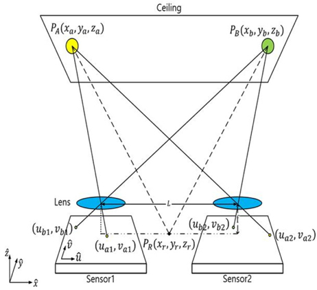
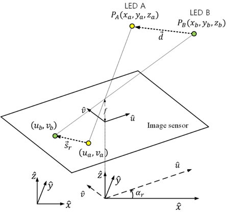
We consider an indoor position estimation model which is shown in Fig. 1. Each LED broadcasts its position information using VLC technology, and a mobile receiver with a dual image sensor is located at the bottom level. The variables are described as follows:
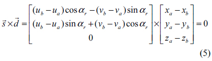
For indoor position estimation, identification of the projected position vectors of the LEDs on the dual image sensor are performed using VLC technology. The proposed indoor position estimation scheme is as follows. First, rotation angle
2.1. Rotation Angle Estimation
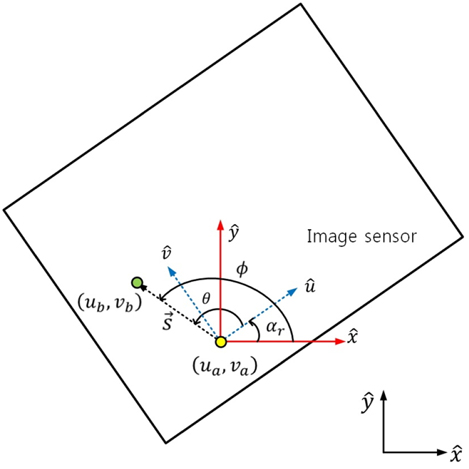
We assume that identification of the projected LED points on the dual image sensor are already performed. Projected two-dimensional position vectors of two LEDs on an image sensor are shown in Fig. 2. If more than two projected LED points are shown in an image sensor, any two points can be selected for the rotation angle estimation. Let LED A and LED B be selected for rotation angle estimation. Then, the projected points of LED A and LED B are (

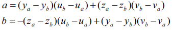
where a

Figure 3 shows LED mapping and the global azimuth angle on an image sensor. The rotation angle of the receiver coordinate system from the world coordinate system is obtained as

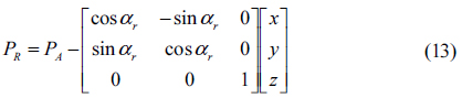
The rotation matrix

From (5), the trigonometric equation is expressed as

with

Because the

2.2. Indoor Position Estimation
We assume that LED A is used for position estimation of the mobile receiver. Let (
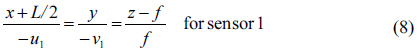

where (-
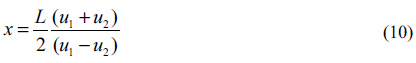
Equations (8) and (9) give
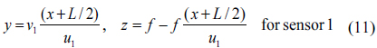
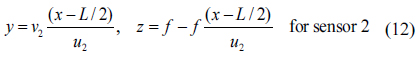
By choosing one of Equations (11) and (12) for a non-zero denominator, the
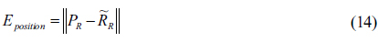
The simulation of the proposed indoor positioning algorithm was performed using MATLAB. In our simulation, a 1×1m2 LED array is considered for the LED lighting and VLC transmitter. Simulation parameters such as the image sensor dimension, the field of view (FOV) of the image sensor, the distance between the centers of the two lenses, and the positioning area of the mobile receiver are listed in Table 1. The positioning error is calculated by applying Euclidean norm of the error vector as follows:
[TABLE 1.] Simulation parameters
Simulation parameters

where is the estimated position vector of the mobile receiver.
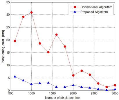
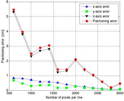
Figure 4 shows the mean absolute positioning error of the proposed positioning algorithm and the conventional positioning algorithm with vector estimation [12]. The number of pixels per line of the image sensor is increased from 600 to 3000 with a step of 200 pixels. For the conventional positioning algorithm with vector estimation, the mean absolute positioning errors for 1000, 1600, 2200, and 3000 pixels per line are 31.02 cm, 21.83 cm, 7.84 cm, and 2.13 cm, respectively. The positioning error shows decreasing zigzags as the number of pixels per line is increased. This is due to the quantization error at the image sensors [12]. With the proposed algorithm, the mean absolute positioning errors for 1000, 1600, 2200, and 3000 pixels per line are 2.49 cm, 1.41 cm, 1.43 cm, and 0.46 cm, respectively. Because of the quantization error, the proposed positioning algorithm also shows zigzagging of the positioning error with the number of pixels per line. However the positioning error of the proposed algorithm is greatly decreased in comparison with the conventional algorithm with vector estimation. That means that proposed algorithm is superior to the conventional method in indoor position estimation.
Figure 5 shows the mean absolute positioning errors of the
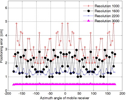
Figure 6 shows the mean absolute positioning error of the proposed positioning algorithm along the azimuth angle, which is increased from -180 degrees to 175 degrees with steps of 5 degrees. The positioning error along the azimuth angle shows a random distribution. That means that the positioning error has no dependency on azimuth angle. We also know that the mean absolute positioning error and the variation of the range of error are reduced when the number of pixels per line is increased.
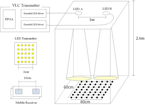
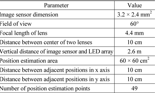
We developed an indoor positioning system and demonstrated the proposed indoor positioning algorithm. Figure 7 shows the experimental model room for the indoor position experiment. The height of the model room is 2.6 m. Two LED lamps are located at the ceiling and are separated by 1 m. Each LED lamp is assembled with 5 × 5 white LEDs and the diameter of each LED is 5 mm. Each LED lamp is modulated for lighting and VLC communication, and the VLC transmitter of each LED lamp performs on-off keying (OOK) modulation to broadcast its position information. A mobile receiver is located at the bottom of the model room, and 7 × 7 points are selected for the indoor position experiment. A mobile receiver is developed for VLC communication and is composed of two Logitech 310 webcams. The dimension of each image sensor is 3.2 × 2.4 mm2, and the distance between centers of the two lenses is 10 cm. In this experiment, two LED lamps broadcast that position information using VLC technology. Hence, identification of the projected LED lamps on the dual image sensor is performed. Some experimental parameters are listed in Table 2.
[TABLE 2.] Experimental parameters
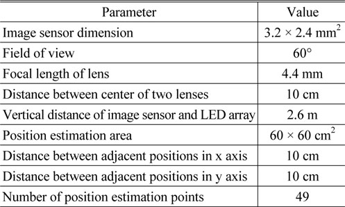
Experimental parameters
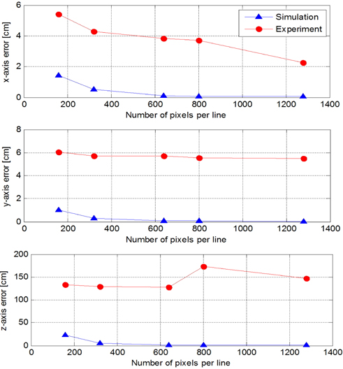
Figure 8 shows the mean absolute positioning error of the developed indoor positioning system at five resolutions: 160 × 120, 320 × 240, 640 × 480, 800 × 600, and 1280 × 960. The simulation errors along the
In this paper, we proposed an indoor position estimation algorithm using LEDs and a dual image sensor. Each lighting LED broadcasts its position information using VLC technology and a mobile receiver with a dual image sensor estimates its three-dimensional position and azimuth angle from the broadcast positions of the two LEDs. Using MATLAB simulation, we showed that the proposed indoor position estimation method gives more accurate positioning results than the conventional method with vector estimation.
Next, we developed an indoor positioning system and demonstrated its performance. From the results of the experiment, the mean absolute positioning error of the