검색 전체 메뉴
PDF
맨 위로
OA 학술지
Resolution Enhanced Computational Integral Imaging Reconstruction by Using Boundary Folding Mirrors
  • 비영리 CC BY-NC
  • 비영리 CC BY-NC
ABSTRACT

In this paper, we present a resolution-enhanced computational integral imaging reconstruction method by using boundary folding mirrors. In the proposed method, to improve the resolution of the computationally reconstructed 3D images, the direct and reflected light information of the 3D objects through a lenslet array with boundary folding mirrors is recorded as a combined elemental image array. Then, the ray tracing method is employed to synthesize the regular elemental image array by using a combined elemental image array. From the experimental results, we can verify that the proposed method can improve the visual quality of the computationally reconstructed 3D images.


KEYWORD
Integral imaging , Elemental images , Resolution enhancement
  • I. INTRODUCTION

    Integral imaging is a technique capable of recording and reconstructing a 3D object with a 2D image array having different perspectives of a 3D object. It has been regarded as the most promising technique because of its full parallax, continuous viewing, and full-color images [1-4]. However, this technique suffers from some problems such as limited image resolution [5-7], narrow viewing angle, and small image depth.

    To overcome the disadvantage of limited image resolution, many modified methods have been proposed [8-12]. A curved computational integral imaging reconstruction technique has been proposed in [11, 12], which is an outstanding method to enhance the resolution of three-dimensional object images. However, the utility of the virtual large-aperture lens may introduce some distortions because of the curving effect in this method.

    In this paper, to improve the resolution of the computationally reconstructed 3D images, we propose a novel approach for the resolution enhanced pickup process by using boundary folding mirrors. In the proposed method, 3D objects are picked up by a lenslet array with boundary folding mirrors as a combined elemental image array (CEIA), which can record more perspective information than the regular elemental image array (REIA) because of the specular reflection effect. The recorded CEIA is computationally synthesized into a REIA by using a ray tracing method. Finally, by using the REIA, the resolution-enhanced 3D images could be computationally reconstructed in the proposed method. To show the feasibility of the proposed method, preliminary experiments are performed.

    II. THE PROPOSED METHOD

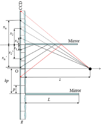
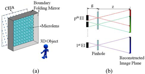
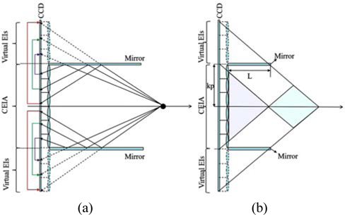
    Figure 1(a) shows the pickup system which uses a lenslet array and boundary folding mirrors to capture 3D objects [13]. Compared with conventional integral imaging system, the pickup systems can record both direct light information from the 3D objects and reflected light information from the boundary folding mirrors. Here, it is worth noting that the reflected information of the CEIA contains extra perspective information from the 3D objects. In order to computationally reconstruct resolution enhanced 3D images, the CEIA is necessary to generate a REIA, especially the reflected information of the CEIA needs to reorganize virtual elemental images (EIs) as shown in Fig. 2 (a). The lenslet array denoted by dashed lines is a virtual lenslet array mirrored by boundary folding mirrors. The red, green and purple arrowed lines denote the mapping directions.

    Before synthesizing the REIA, the maximum number of additional microlenses nmax should be determined. With a size 2k×2k lenslet array, there exist two restrictions conditions on the length of boundary folding mirrors and the pitch size of microlenses:

    image

    where L is the length of the boundary mirror, ⌈ · ⌉ is the rounding operator. Then, to measure the best pickup area for all the microlenses including the additional ones, each elemental image must contain reflected information as shown in the green area of Fig. 2(b). Therefore, the best pickup area r along the z axis can be calculated as:

    image

    If the 3D objects are located in the purple area of Fig. 2(b), the reflected information cannot be recorded through the additional microlenses. If the 3D objects are located out of the green and purple areas of Fig. 2(b), some but not all of the additional microlenses can be exploited for recording reflected information

    Next, we consider only the one dimensional case to simplify the mapping relationship between the reflected information of the CEIA and the virtual EIs. Suppose that an object point is located at a longitudinal distance z away from the lenslet array, and the gap between the sensor and the lenslet array is g as shown in Fig. 3. Based on the specular reflection, the distance xn between the reflection point in CEIA and the boundary mirror is equal to the distance xn between reflected object point in virtual EIs and the boundary mirror:

    image

    Then, we can get the mapping relationship between the reflected information of the CEIA E and the REIA Er :

    image
    image

    where n is the number of additional microlenses, c is the pixel size. The remaining information of the CEIA except for the reflected information can be directly mapped into the REIA:

    image

    By using the Eq. (4) and Eq. (6), the REIA Er can be obtained with the size of (2k + n)p × (2k + n)p. Compared with the conventional integral imaging method, the visual quality of the reconstructed 3D images will be improved by using the proposed method, because the reflected elemental images can provide additional 3D information.

    In the computational integral imaging reconstruction process, a high resolution 3D scene can be reconstructed based on the back-projection model. The 3D image reconstructed at (x, y, z) is the summation of all the inversely mapped REIA:

    image

    where R(x, y, z) denotes the reconstructed 3D images, sx and sy are the sizes of elemental image , respectively, M is the magnification factor which is defined as M = z/g.

    III. EXPERIMENTAL RESULTS

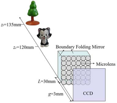
    To demonstrate the feasibility of the proposed method, we performed some experiments with 3D objects composed of a cat and a tree as shown in Fig. 4.

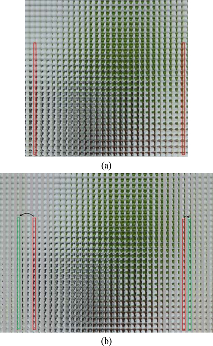
    In the experimental setup, the gap between the imaging sensor and the lenslet array was set to 3 mm, which is equal to the focal length of the microlens. The 3D objects cat and tree are located 120 mm and 135 mm from the lenslet array, and the length of the mirror is 30 mm. Here, the lenslet array is composed of 30×30 microlenses, and each microlens has a uniform size of 1.05 mm ×1.05 mm with focal length of 3 mm. Figure 5(a) shows a captured CEIA, in which the pixel number of each EI is 50×50. There exists mirror reflected information of a 3D object in the CEIA because of the boundary folding mirrors, as shown in the red block of Fig. 5(a). As we discussed earlier, to synthesize the REIA, the 6 additional lenses are determined by using Eq. (3). Then, the REIA is synthesized by using the reflected information of CEIA, in which the REIA contains more 3D perspectives, as shown in the green block of Fig. 5(b).

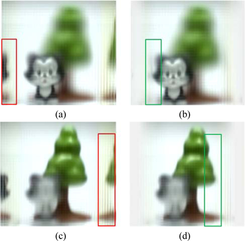
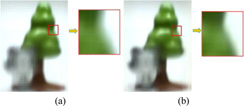
    In the experimental results, we utilized the original captured CEIA and synthesized REIA to reconstruct the 3D images. The 3D objects cat and tree are reconstructed at distances 120 mm and 135 mm, respectively. Figure 6(a) and 6(c) are the computationally reconstructed 3D images by using the CEIA, where the reconstructed images are focused on the cat and the tree, respectively. The region of the red block is the reflected 3D information. Figure 6(b) and 6(d) are the computationally reconstructed 3D images by using the REIA, where the reconstructed images are focused on the cat and the tree, respectively. Compared with the region in the red block of Fig. 6(a) and 6(c), the reflected light information is overlapped on the direct light information as shown in green block of Fig. 6(b) and 6(d). This can significantly improve the quality of the computationally reconstructed 3D images by using a REIA. In addition, the zoomed-in region of the Figs. 7(a) and 7(b) confirm that the visual quality of the computationally reconstructed 3D images by using the REIA is sharper than by using the CEIA. From the experimental results, we confirm the feasibility of the proposed method.

    IV. CONCLUSIONS

    In conclusion, we have presented a resolution-enhanced computational 3D reconstruction method by using boundary folding mirrors in an integral imaging system. In the proposed method, a CEIA that contains extra reflected perspective information is picked up firstly by using a lenslet array combined with boundary folding mirrors. The generated REIA is synthesized from the captured CEIA, in which the REIA is used to reconstruct resolution-enhanced 3D images. The experimental results confirmed the feasibility of the proposed system.
참고문헌
  • 1. Jang J. S., Javidi B. (2002) “Improved viewing resolution of three-dimensional integral imaging with nonstationary microoptics,” [Opt. Lett.] Vol.27 P.324-326 google cross ref
  • 2. Stern A., Javidi B. (2006) “Three-dimensional image sensing, visualization, and processing using integral imaging,” [Proc. IEEE] Vol.94 P.591-607 google cross ref
  • 3. Yoo H., Shin D.-H. (2007) “Improved analysis on the signal property of computational integral imaging system,” [Opt. Express] Vol.15 P.14107-14114 google cross ref
  • 4. Lee B.-G., Kang H.-H., Kim E.-S. (2010) “Occlusion removal method of partially occluded object using variance in computational integral imaging,” [3D Research] Vol.1 P.6-10 google
  • 5. Hoshino H., Okano F., Isono H., Yuyama I. (1998) “Analysis of resolution limitation of integral photography,” [J. Opt. Soc. Am. A] Vol.15 P.2059-2065 google cross ref
  • 6. Jang J.-S., Jin F., Javidi B. (2003) “Three-dimensional integral imaging with large depth of focus using real and virtual image fields,” [Opt. Lett.] Vol.28 P.1421-1423 google cross ref
  • 7. Jang J.-S., Javidi B. (2003) “Improvement of viewing angle in integral imaging by use of moving lenslet arrays with low fill factor,” [Appl. Opt.] Vol.42 P.1996-2002 google cross ref
  • 8. Piao Y., Zhang M., Shin D., Yoo H. (2013) “Three-dimensional imaging and visualization using off-axially distributed image sensing,” [Opt. Lett.] Vol.38 P.3162-3164 google cross ref
  • 9. Zhang M., Piao Y., Kim N.-W., Kim E.-S. (2014) “Distortion-free wide-angle 3D imaging and visualization using off-axially distributed image sensing,” [Opt. Lett.] Vol.39 P.4212-4214 google cross ref
  • 10. Zhang M., Piao Y., Lee J.-J., Shin D., Lee B.-G. (2014) “Visualization of partially occluded 3D object using wedge prism-based axially distributed sensing,” [Opt. Commun.] Vol.313 P.204-209 google cross ref
  • 11. Hyun J.-B., Hwang D.-C., Shin D.-H., Kim E.-S. (2007) “Curved computational integral imaging reconstruction for resolution-enhanced display of three-dimensional object images,” [Appl. Opt.] Vol.46 P.7697-7708 google cross ref
  • 12. Piao Y., Kim E.-S. (2009) “Resolution-enhanced reconstruction of far 3-D objects by using a direct pixel mapping method in computational curving-effective integral imaging,” [Appl. Opt.] Vol.48 P.222-230 google cross ref
  • 13. Hahn J., Kim Y., Lee B. (2009) “Uniform angular resolution integral imaging display with boundary folding mirrors,” [Appl. Opt.] Vol.48 P.504-511 google cross ref
이미지 / 테이블
  • [ FIG. 1. ]  The proposed system.
    The proposed system.
  • [ FIG. 2. ]  (a) Geometrical relations between EIs and 3D object, (b) Limitation of the pickup range.
    (a) Geometrical relations between EIs and 3D object, (b) Limitation of the pickup range.
  • [ ] 
  • [ ] 
  • [ FIG. 3. ]  Specific analysis of mapping relation between the reflected parts in the captured elemental images and the mirror folded region.
    Specific analysis of mapping relation between the reflected parts in the captured elemental images and the mirror folded region.
  • [ ] 
  • [ ] 
  • [ ] 
  • [ ] 
  • [ ] 
  • [ FIG. 4. ]  Experimental setup.
    Experimental setup.
  • [ FIG. 5. ]  (a) CEIA, (b) REIA.
    (a) CEIA, (b) REIA.
  • [ FIG. 6. ]  The cat images reconstructed at z=120 mm by using (a) CEIA, and (b) REIA; The tree images reconstructed at z=135 mm by using (c) CEIA, and (d) REIA.
    The cat images reconstructed at z=120 mm by using (a) CEIA, and (b) REIA; The tree images reconstructed at z=135 mm by using (c) CEIA, and (d) REIA.
  • [ FIG. 7. ]  Visual quality comparison of the reconstructed tree images by using (a) CEIA, and (b) REIA.
    Visual quality comparison of the reconstructed tree images by using (a) CEIA, and (b) REIA.
(우)06579 서울시 서초구 반포대로 201(반포동)
Tel. 02-537-6389 | Fax. 02-590-0571 | 문의 : oak2014@korea.kr
Copyright(c) National Library of Korea. All rights reserved.