The optoelectronic oscillator (OEO) is a microwave oscillator that utilizes electro-optic and photonic components to store the optical energy instead of using electronics and radio-frequency resonators [1]. While a laser and an electro-optic modulator (EOM) are used in the electro-optic part, an optical delay line and a photo detector are employed in the photonic part of the OEO. Such an OEO was first introduced by Neyer and Voges in 1982 [2]. In that work, a He-Ne laser and Mach-Zehnder type EOM were used as a light source and an intra-loop modulator, respectively. The EOM modulates the light from the laser, and a photo detector measures the beating signal between the carrier and the sideband. The beating signal is amplified and fed back to the EOM to complete the positive feedback loop. The band pass filter is employed to sustain single mode operation of the OEO. With the advent of electro-optic and photonic components operating at tens of GHz, the OEO was revived by Yao and Maleki in 1996 [1].
Because the OEO provides microwave frequency with good spectral purity over a wide frequency range that is only constrained by RF electronics such as amplifiers, OEOs have many applications, for example, metrology [3] and communications [4]. In addition, different types of OEO have been demonstrated in various sensors with good resolution because the oscillation frequency of the OEO is correlated with the loop delay. In the case of the OEO for refractive index measurement [5], for example, a transparent material such as acetonitrile was used to fill the intra-loop cell. This resulted in a refractive index of 1.281 with the standard deviation of 0.010. In their experiment, a 500-m fiber was employed to enhance the stability of the OEO frequency. OEOs were also used to measure the optical fiber length of 2.119 km with the standard deviation of 14.8 μm [6], the transverse load with sensitivity of 9.73 GHz/(N/mm) [7], and acoustic velocity in an acousto-optic modulator consisting of tellurium dioxide (TeO2) with the result of (4.26±0.04)×103 m/s [8].
An OEO with a conventional configuration, in general, is not stable due to its low Q factor, which causes a large frequency drift. In order to enhance the Q factor, the capacity of the optical energy storage has to be increased. This is because the Q factor is proportional to the loop delay of the microwave signal in the OEO [1]. One method by which to increase the loop delay is to use a longer optical fiber. This configuration is very simple and provides an ultra-low phase noise level of -160 dBc/Hz at 10 kHz offset frequency, with 10 GHz oscillation frequency [9]. Using a longer optical fiber, however, increases the risk of multimode operation due to the reduced free spectral range (FSR). By adding an additional shorter loop, the adjacent parasitic modes are efficiently eliminated, so that dual loop OEO ensures stable single mode operation [10]. An optical fiber a few kilometers long is bulky and the length of the optical fiber has to be precisely controlled using an active temperature controller, to compensate phase variations. As alternatives, either a narrow-band pass filter in the electronic path [11], or a Fabry-Perot cavity as a microwave filter in the optical path [12] can be inserted to operate the OEO in single mode. Another method to increase the loop delay is to use a whispering gallery-mode (WGM) resonator as both a modulator and an optical storage element [13-15]. In these cases, the oscillation frequency of the OEO is determined by the FSR of the WGM resonator so that the spurious noise in the microwave spectrum resulting from the longer loop delay disappears. Even when the device is compact, however, a longer optical fiber is still needed to reach a low phase noise level.
In this article, we report a dual loop OEO with acoustooptic delay line. An acousto-optic modulator (AOM) is employed to produce an RF signal and to store the optical energy in the acoustic wave path. When the positive feedback loop is closed, the FSR, and therefore the oscillation frequency of the OEO, are functions of the total loop length of the OEO. These are proportional to the propagation time of the acoustic wave in the AOM. Because the speed of light is almost 105 times faster than the acoustic velocity in the AOM, the AOM-based OEO achieves a high Q factor with only a few centimeters acoustic delay without using a longer optical delay line. In addition, a second loop with a shorter acousto-optic delay is added to the OEO in the same AOM, to compose an AOM-based dual loop OEO that operates in single mode. The oscillation frequency of our OEO is 150 MHz and the effective loop length is 3.8 km. As a result, we achieve a low phase noise level of -118 dBc/Hz at 10 kHz frequency offset, and -140 dBc/Hz at 200 kHz frequency offset.
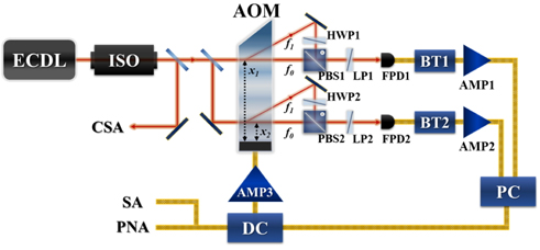
Figure 1 shows the OEO setup with a dual loop configuration based on an acousto-optic delay line. A diode laser with a diffraction grating, which forms an external cavity, is used as a light source of 780 nm wavelength. Optical power of 65 mW, at an injection current of 120 mA, goes through an optical isolator (ThorLabs Model IO-3-780-HP) with 90% transmission and 40-dB isolation of the optical feedback to the diode laser. To confirm single-longitudinal-mode operation of the laser by monitoring the frequency
When the output from the optical isolator is coupled to an AOM (IntraAction Model ATM-1503DE2), the laser beam is split into two paths with the same power. One beam passes through the AOM on the far side from a transducer, which produces an acoustic wave of 150 MHz to compose a longer acousto-optic delay loop. The other beam passes through the AOM, near side from the transducer for a shorter loop. The AOM modulates each laser beam and produces sidebands with a 3-dB bandwidth of 30 MHz, which serve as an RF band pass filter. Although diffraction efficiency is dependent on the distance between the beam and the transducer in the AOM, the incident angles of two beams to the AOM are slightly adjusted to have the same diffraction efficiency about 50% at a driving power of 1 W. Due to the well-known acousto-optic interaction, the sidebands are deflected and then split from the carriers with a frequency of
The longer loop output from the PBS1 goes through a linear polarizer (LP1) of which the polarization axis is rotated by 45° with respect to the vertical axis to make linear polarizations of the two components, which are initially perpendicular, parallel. Then, a fast photo detector (FPD1, Hamamatsu Model G4176-03) measures the 150 MHz beating signal between the carrier
The output from the PBS2 is the same as described above. The carrier and the sideband are overlapped at PBS2 and recover the beating signal using an FPD2. To combine two beating signals from the longer delay loop via AMP1, and the shorter delay loop via AMP2, a power combiner (PC, Mini-Circuits Model ZFSCJ-2-3-S+) is employed with a 1 dB insertion loss and 33 dB isolation. The output from the PC is sent to a directional coupler (DC, Mini-Circuits Model ZFDC-10-1). The coupled output of the DC is used to monitor the microwave spectrum with a spectrum analyzer (Agilent Technologies Model E5052B) and to measure the phase noise of the AOM-based dual loop OEO with a phase noise analyzer (Agilent Technologies Model N9093A). Another output of the DC is further amplified by a high-power amplifier (AMP3, Mini-Circuits Model ZHL-1-2W+) and is injected into the driving port of the AOM to complete the OEO loop. A previous setup in Ref. [8] is modified by composing a dual loop with the custom AOM, which has a longer propagation length of acoustic wave.
When we optimize the operation of the AOM, and also arrange the RF parts, a microwave synthesizer is connected to the AMP3 to drive the AOM at around 150 MHz. During the OEO operation, however, the microwave synthesizer is replaced and the sidebands are produced by closing the positive feedback loop of the beating signals.
III. OEO OPERATION AND RESULTS
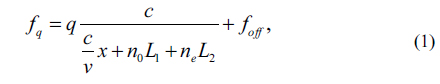
When the AOM-based OEO with a single loop operates, the oscillation frequency

where
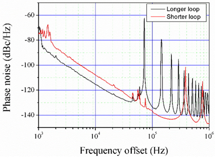
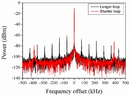
We first disconnect the shorter delay loop by blocking the laser beam in front of the FPD2 to operate the AOMbased OEO with a single loop. We apply an adequate amount of loop gain by using three AMPs, as shown in Fig. 1, to achieve sustainable oscillation during OEO operation. Either the optical power coupled to the AOM or the power supply voltages applied to three AOMs, is adjusted to vary the positive feedback gain. The RF spectrum of the OEO, as shown in Fig. 2, is measured with a black line. There are several peaks satisfying the phase boundary condition of the OEO. Although the propagation length of the acoustic wave is about 5 cm, the free spectral range of the longer acousto-optic delay loop between adjacent modes is around 80 kHz. This implies an effective OEO loop length of 3.8 km, ensuring an adequate Q factor without using a bulky optical fiber. During operation, 0 dBm of RF power is applied to the AMP3. In Fig. 3, the black line represents the phase noise of the OEO with the longer acousto- optic delay loop. The phase noise reaches -115 dBc/Hz at 10 kHz frequency offset. Next, the AOM-based OEO is switched over to the shorter delay loop and its RF spectrum and phase noise are measured. The results are shown in Fig. 2 and Fig. 3 with a red line. The free spectral range of the shorter acousto-optic delay loop is 380 kHz, resulting from the effective OEO loop length of 780 m. The phase noise is -107 dBc/Hz at 10 kHz frequency offset.
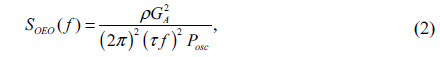
Although the effective OEO loop length of the longer delay loop is five times longer than that of the shorter case, only 8 dBc/Hz improvement of the phase noise is achieved. For an ideal case, the phase noise of the OEO is given by the relation [1, 10], where

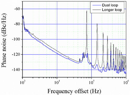
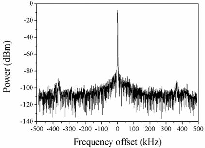
By combining two loops, we compose an AOM-based dual loop OEO and investigate its characteristics. Figure 4 shows the RF spectrum of the dual loop OEO. The center frequency of the RF spectrum is around 150 MHz, with stable single mode operation. Note that several peaks displayed in each single loop almost disappear due to the destructive interference between the modes from shorter and longer delay loops. To suppress the other modes of the longer delay loop, the accumulated phase of the shorter delay loop is adjusted by varying the length of RF cable between the AMP2 and the DC until finding the optimal oscillation frequency, at which the suppression ratio is maximized. The suppression ratio of the other mode is more than 50 dB. For the spectrum, the resolution bandwidth and the data point of the spectrum analyzer are set to 1 kHz and 5000 points, respectively.
Figure 5 shows the phase noise of the AOM-based dual loop OEO. The phase noise is -118 dBc/Hz at 10 kHz frequency offset, and reaches -140 dBc/Hz at 200 kHz frequency offset, respectively. In comparison with the result of the longer delay loop, there is 3 dB enhancement of the phase noise resulting from the increase of the oscillation power. This is due to the single mode operation. The slope of the phase noise shows different function of the frequency offset. From 100 Hz to 10 kHz frequency offset, the phase noise slope is -30 dB/decade, which is 10 dB/decade higher than in Eq. (2), corresponding to a 1/
Although the oscillation frequency of our AOM-based dual loop OEO is lower than that of typical OEOs, where a Mach-Zehnder type EOM made of lithium niobate or WGM resonator is used, its frequency can be increased to the GHz range at the expense of some degradation of the marginal diffraction efficiency [16]. In the case of 2.5 GHz modulation frequency, for example, the diffraction efficiency is 20% at a driving power of 1 W [16]. In addition, with the advent of micromechanical resonator technology, a silicon-AOM-based OEO operates at 2.05 GHz with 18 dBm output power and phase noise of -100 dBc/Hz at 100 kHz frequency offset [17]. In their experiment, the oscillation frequency of the OEO is increased to 6.15 GHz with -5 dBm output power and phase noise of -88 dBc/Hz at 100 kHz frequency offset, by allowing third-order harmonics. The use of an AOM with a higher center frequency also implies the shortening of the optical path to overlap the carrier and the sideband after the AOM.
We note that a huge effective loop length gain based on the difference between the speed of light and the acoustic velocity facilitates size reduction, and therefore easy temperature stabilization of the system. In addition, precise frequency stabilization of the light source is not needed because the frequency drift of the light source, which is the carrier, only causes common-mode frequency shifting between the carrier and the sidebands.
We have constructed and characterized a dual loop OEO with an acousto-optic delay line. An AOM is employed as a modulator to produce RF signal and also as a delay line simultaneously. By using the well-known acousto-optic interaction, the effective OEO loop length can be increased to 3.8 km with a few centimeters of acousto-optic delay line. As one laser beam passes through the AOM, far side from a transducer, to compose a longer delay loop, the other laser beam passes through the AOM, near side from the transducer, for a shorter delay loop, to complete the dual loop configuration. The oscillation frequency of the AOM-based dual loop OEO is 150 MHz and the phase noise is -118 dBc/Hz at 10 kHz and -140 dBc/Hz at 200 kHz frequency offset, with stable single mode operation. Its results are comparable to that of the OEO using a WGM resonator but four orders of magnitude worse than -160 dBc/Hz at 10 kHz frequency offset of a conventional OEO using ~ 3 km of optical fiber. By employing an EOM as a modulator and an AOM as a delay loop, the oscillation frequency of the OEO should be increased and lower phase noise could be achieved.