Over the past two decades, optical image encryption techniques have played an important role in the information security field. Since development of the double random phase encryption (DRPE) technique [1], in which the image is encoded to be a white noise pattern with two statistically independent random phase masks (RPM), a number of improved DPRE-based image encryption methods have been proposed, to achieve higher security [2-7]. Most of the optical encryption methods can be viewed as symmetric cryptosystems, in which the keys for encryption and decryption are identical [8]. However, earlier studies indicated that these cryptosystems are lacking in security strength, because of the inherently linear property of mathematical or optical transformation, and are vulnerable to various attacks such as chosen plaintext attack [8-11]. In addition, most schemes mainly focused on single-image encryption, which leads to deficiency in multiple-image encryption and transmission [8].
To avoid the problems that arise from the linearity and symmetry of DRPE, an asymmetric encryption scheme based on phase truncated Fourier transforms has also been proposed [12], in which the encryption keys (public keys) are different from the decryption keys (private keys). However, when RPMs are used as public keys to encrypt different plaintexts, this method is still vulnerable to specific attacks such as known public key attack [13, 14]. To enhance security, it has been further extended from the Fourier transform (FT) domain to the Fresnel transform (FST) domain [15], the fractional Fourier transform (FrFT) domain [8], the Gyrator transform (GT) domain [11, 16], etc. To improve the efficiency of image transmission and communication over a network, more and more multiple-image encryption methods have been proposed [17-21]. Situ and Zhang reported the wavelength multiplexing-based multiple-image encryption scheme [16]. Using DRPE and an orthogonal encoding technique, Lee and Cho presented a multiple-image encryption method [18]. Based on the nonlinear amplitude-truncation (AT) and phase-truncation (PT) operations in the FT domain, Wang and Zhao developed an asymmetric multiple-image encryption scheme [19]. Based on coupled logistic maps and an iterative phase-retrieval process, Sui
In this paper, based on the octonion Fresnel transform (OFST) and two-dimensional Sine Logistic modulation map (2D-SLMM), a novel asymmetric multiple-image encryption method is presented. In the proposed approach, first the OFST is defined and its calculation for an octonion matrix is developed. Then multiple images are processed holistically in a vectorial manner using OFST. Subsequently, the components of the OFST-transformed images are combined to construct the input complex amplitude. To improve robustness against attacks, the input information is modulated by a phase mask, which is generated based on 2D-SLMM. The initial values of the SLMM, which is computed using the components of the OFST-transformed images, are used as decryption keys. With AT, PT, and RPMs, the complex amplitude is encrypted in the Fresnel domain, and two decryption keys are produced in the encryption process. To enhance security, the encrypted result and two decryption keys are permuted by the proposed SLMM-based scrambling method. During decryption, the eight original grayscale images can be recovered with the correct encryption and decryption keys. Numerical simulations are presented to demonstrate the feasibility and performance of this encryption.
In this section, we discuss some related theories before extending the traditional FST to the octonion domain, showing how to calculate the OFST of an octonion matrix, and designing the 2D-SLMM-based scrambling technique, etc.
Octonions can be viewed as octets (or 8-tuples) of real numbers [24] and have been applied in image processing, such as image saliency detection [25]. An octonion can be represented as follows [24, 25]:

where ζ0,

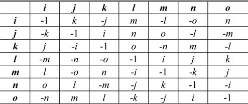
The addition and subtraction of octonions are performed by adding and subtracting corresponding terms [25]. However, the multiplication of octonions is neither commutative nor associative [24, 25]. The multiplication rules, which describe the result of multiplying the element in the
[TABLE 1.] Octonion multiplication table

Octonion multiplication table
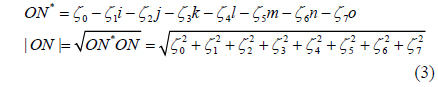
The conjugate and modulus of an octonion are respectively defined by [25]

When
The Fresnel transform of a function
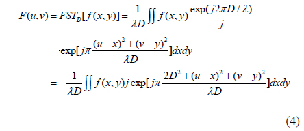
where
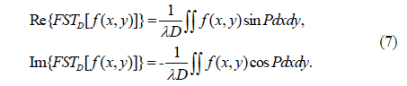
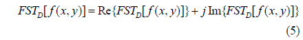
Since the FST of

where Re(
For simplicity, let
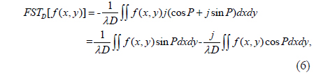
Comparing Eqs. (5) and (6), the real and imaginary parts of
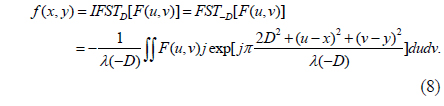
The inverse Fresnel transform (IFST) means an FST of a Fresnel diffraction pattern with the distance parameter –

2.3. The Asymmetric Encryption Technique in The Fresnel Domain
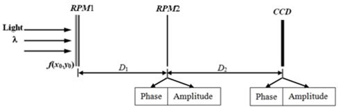
Based on the amplitude-truncated and phase-truncated strategy, an asymmetric cryptosystem in the Fresnel domain was reported in [15]. Figure 1 shows the schematic optical encryption setup for this asymmetric cryptography [15]. In Fig. 1, three planes are defined as the input plane, the transform plane, and the output plane. The corresponding coordinates of the three planes are denoted respectively by (
In the asymmetric encryption method in the Fresnel domain, when the system is illuminated by a collimated plane wave of wavelength
2.4. 2D Sine Logistic Modulation Map
Due to their excellent properties, such as sensitivity to initial conditions and control parameters, chaotic maps are employed to encrypt the image, which can strengthen the nonlinearity of the image [8]. Since 2D-SLMM offers a wider chaotic range and better ergodicity and hyperchaotic properties than existing chaotic maps [28], it has been chosen to design the scrambling method and generate the RPMs in this study. 2D-SLMM is defined as [28]

where 0 ≤
III. OCTONION FRESNEL TRANSFORM
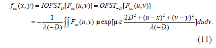
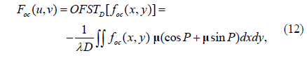
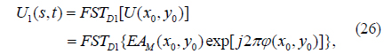
Similar to Eq. (4), the right-side OFST with respect to
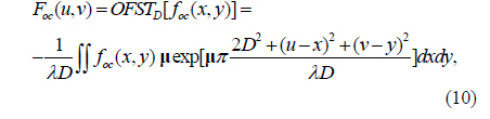
where
Corresponding to OFST, the inverse right-side OFST (IOFST) is defined as
Here,
The method that utilizes the existing FST algorithm to calculate the OFST of an octonion matrix is developed in this subsection. Using the FST algorithm, the OFST can be implemented efficiently.
Let
Since
where
Considering the general unit pure octonion μ=
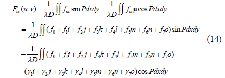
Using Eq. (7), Eq. (15) can be obtained after calculating Eq. (14):
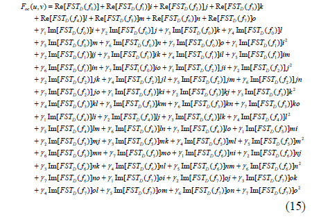
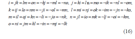
From Table 1, we have

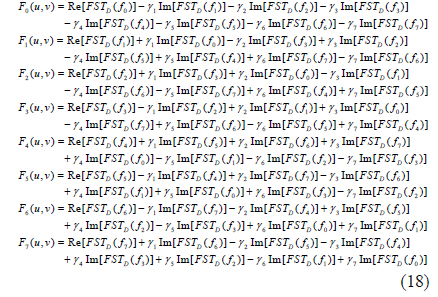
Substituting Eqs. (2) and (16) into Eq. (15), we have
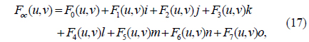
where

It can be seen from Eq. (18) that each coefficient in
where
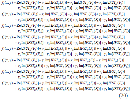
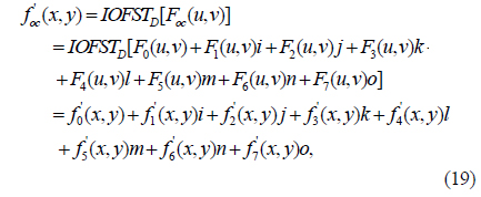
In Eq. (20),
As can be seen from formulas (14)-(20), the right-side OFST and IOFST of an octonion matrix can be calculated effectively using the traditional FST and IFST algorithms.
IV. THE 2D SLMM-BASED RANDOM-PHASE-MASK-GENERATION METHOD AND 2D SLMM-BASED SCRAMBLING METHOD
Singh
4.1. The SLMM-based Random-Phase-Mask-Generation Method
The procedure for generating the RPM can be described as follows:
1) Initialize
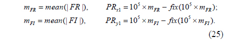
2) Compute the chaotic sequences
Here, fix(
3) Construct a new 1D sequence
4) Convert the sequence
5) With the random distribution
4.2. The SLMM-based Scrambling Method
The scrambling method is described as follows:
1) Initialize
2) With

3) Using the quicksort algorithm [33], sort
4) With
for (
Here, ceil(
The inverse image-scrambling (decryption) process is similar to the image-scrambling process. In decryption, first find the permutation indices
for (
In the above loop procedure,
V. THE PROPOSED ASYMMETRIC MULTIPLE-IMAGE ENCRYPTION AND DECRYPTION
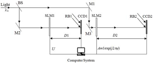
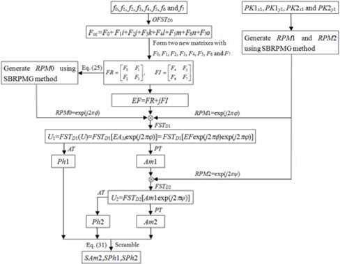
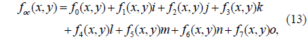
Since an octonion contains a real part and seven imaginary parts, eight images can be represented by an octonion, as shown in Eq. (13). Using this representation, eight images can be processed holistically in a vectorial manner using OFST. Therefore, based on the OFST and 2D-SLMM, an asymmetric multiple-image encryption scheme in the Fresnel domain is presented. In the proposed method, at most eight images can be encrypted simultaneously. Since amplitude and phase can be modulated simultaneously by an SLM [35], the proposed method can be implemented using an optical or digital approach. Figure 2 shows the optoelectronic setup of the proposed encryption process. In Fig. 2, BS is a beam splitter, M1, M2, and M3 are mirrors, and RB1 and RB2 are two reference beams that are split from the light source. SLM1, CCD1, and CCD2, which are computer-controlled, are located respectively in the input plane, the transform plane, and the output plane. Supposing
1) To treat the eight images in a holistic manner,
2) With the distance
3) Using
4) Let
5) To enhance robustness against attacks such as the known public key attack, the complex amplitude

where mean(
6) The complex amplitude
7) Import
where FST() is the Fresnel transform operation. Then the amplitude

where PT() denotes tphase truncation, the operation of truncating the phase part while retaining the amplitude part [19], and AT() stands for amplitude truncation, the operation of truncating the amplitude part while retaining the phase function distributed on the interval [0,2π ] [8, 19].
8) Subsequently, the real amplitude

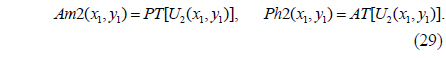
The amplitude of the resultant distribution, which is the encrypted signal, and the corresponding phase function are obtained by the PT and AT operations as follows:

9) To enhance security,
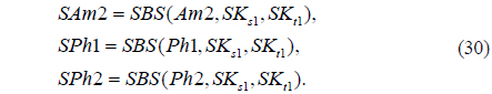
where SBS() is the SLMM-based scrambling operation.

where rdp(
In the encryption process mentioned above, steps (1)-(6) and (9) will be performed digitally. As shown in Fig. 2, the complex function
In the proposed encryption method, the parameters
In addition, eight grayscale images all of size
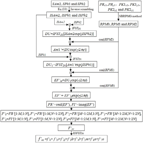
The steps of the decryption process are given as follows.
1) The ciphertext

where ISBS() is the inverse SLMM-based scrambling operation. The parameters
2)
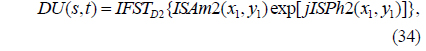
where IFST() is the inverse Fresnel transform operation.
3)

4)

5)

6)

7) Take the real part

where real(
8) First, let
9) Apply IOFST to
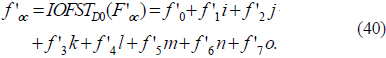
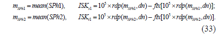
Thus,
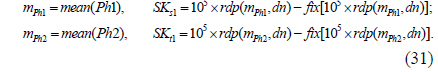
As can be seen from Eqs. (31) and Eq. (33), the mean values of
Figure 4 depicts the decryption process. In Fig. 4, conj (
VI. NUMERICAL SIMULATION RESULTS
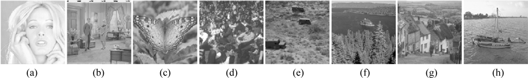
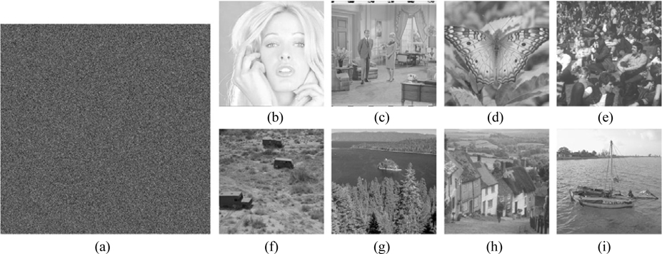
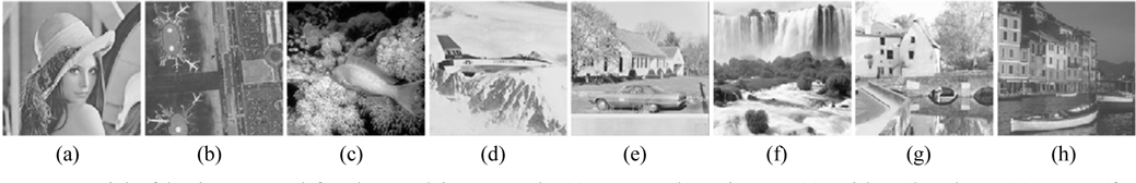
To verify the feasibility of the proposed encryption technique, numerical simulations are performed on the eight grayscale images “Girl”, “Couple”, “Butterfly”, “Crowd”, “Truck”, “Lake”, “Goldhill” and “Boat”, all of size 256×256, shown in Fig. 5. The tests are carried out on a notebook computer with Intel(R) Core(TM) i7-4700HQ CPU @ 2.40 GHz and 8 GB of DDRL3 RAM, and with MATLAB R2013a. In the experiments, the system parameters are μ = (

where
6.1. Performance of the Encryption System
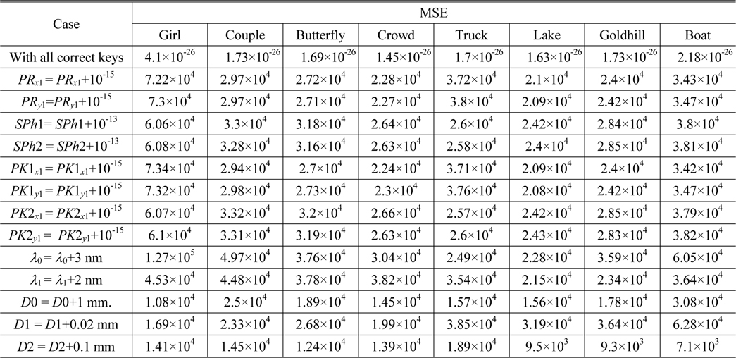
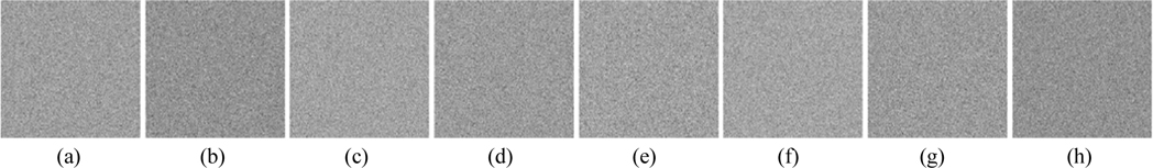
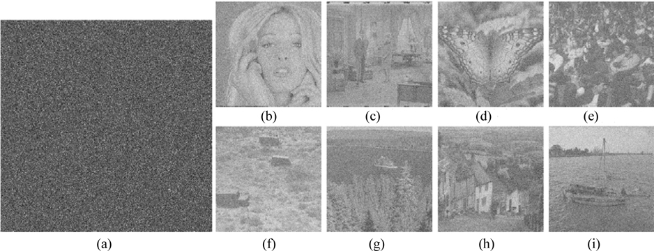
Using the proposed encryption scheme, the eight plaintext images are encrypted, and the ciphertext shown in Fig. 6(a) is obtained. To investigate the performance of the proposed scheme, the ciphertext is decrypted using both correct and incorrect keys. The MSEs between original and decrypted images are listed in Table 2. Figs. 6(b)-(i) display the eight images retrieved with the correct keys respectively. They are perfect, without any noise or distortion. As shown in Table 1, all the corresponding MSEs are approximately zero.
[TABLE 2.] MSEs of the eight images decrypted using correct and incorrect keys

MSEs of the eight images decrypted using correct and incorrect keys
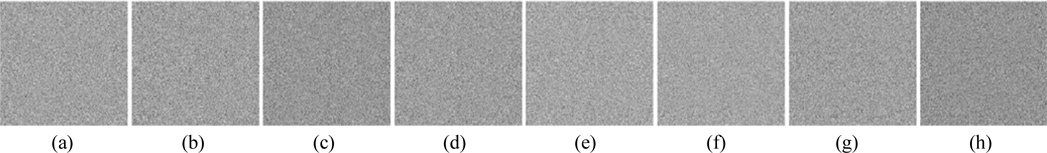
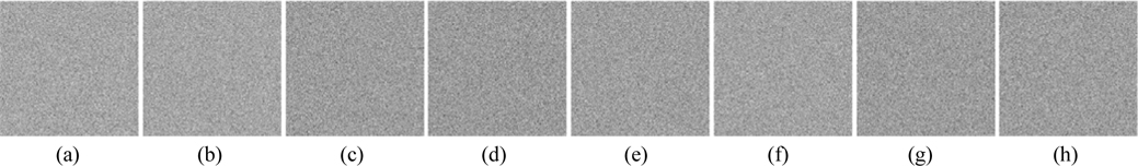
As a multiple-image encryption scheme based on an asymmetric technique, the decryption keys play an important role. To evaluate the influence of the decryption keys, cases in which
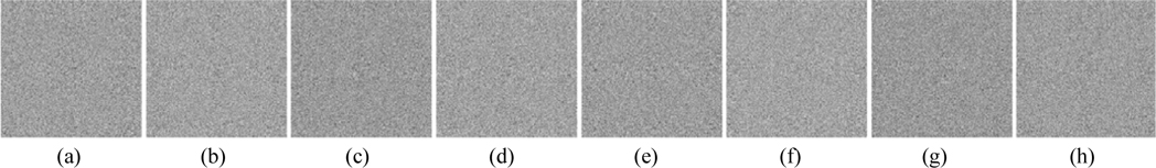
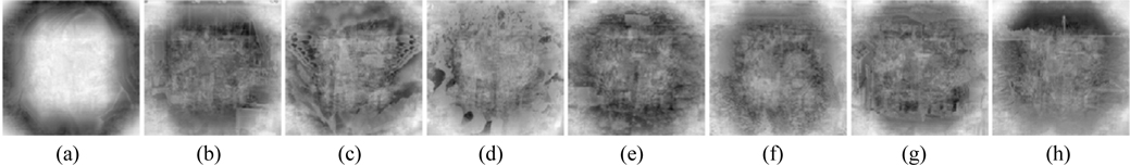
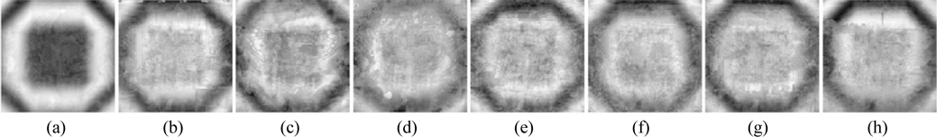
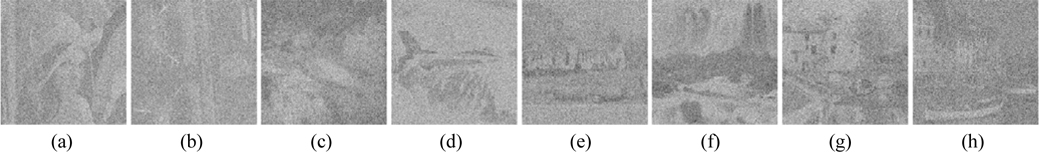
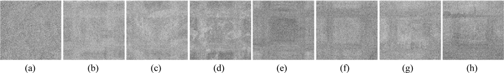
Now we investigate the sensitivity of retrieved images to a small change in the parameters of the 2D SLMM-based RPM generation technique. Figs. 11-14 show the images decrypted with the wrong keys
The performance of security parameters
Please note that in the aforementioned experiments, the other keys remain correct while a key is changed (except for the experiment carried out with all correct keys).
Next, we evaluate the key space of the proposed asymmetric encryption method. In term of the description of the proposed scheme, we know that the key space of the cryptosystem consists of the encryption keys
6.2. Robustness of the Proposed Cryptosystem Against Attacks
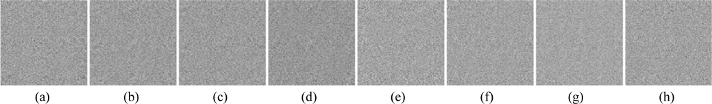
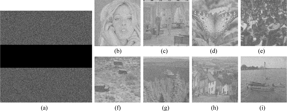
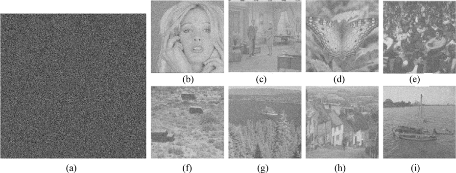
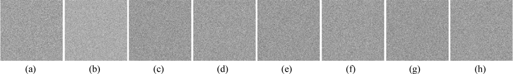
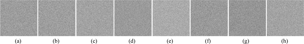
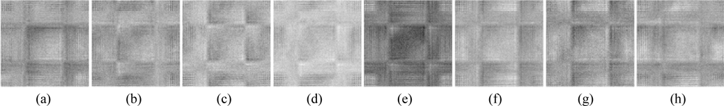
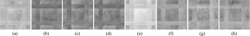
Information loss or noise contamination may occur during data transmission. Now, the robustness of this method against occlusion attack, which is viewed as data loss, is tested. Figure 20(a) shows the ciphertext occluded by 25%. The retrieved images acquired by employing all correct keys are illustrated in Figs. 20 (b)-(i). All of the decrypted images can be distinguished, and their corresponding MSEs are 2.95×10³, 1.98×10³, 1.93×10³, 1.76×10³, 1.74×10³, 1.7×10³, 1.82×10³, and 2.13×10³. It is well known that Gaussian noise [37] and salt-and-pepper noise [37] appear frequently during transmission. The robustness of the cryptosystem against noise attacks is further probed. Figure 21(a) is the ciphertext polluted by Gaussian noise with mean value 0 and standard deviation 25. Figures 21(b)-(i) are the recovered images, and their corresponding MSEs are 3.77×10⁴, 1.38×10⁴, 1.27×10⁴, 8.19×10³, 7.65×10³, 6.35×10³, 104, and 1.81×10⁴. Figure 22(a) shows the ciphertext damaged by salt-and-pepper noise with density 0.05. Figures 22(b)-(i) depict the retrieved images with corresponding MSEs of 3.74×10⁴, 1.36×10⁴, 1.26×10⁴, 8.12×10³, 7.59×10³, 6.27×10
Four potential attacks, including cipher only attack, known plaintext attack, chosen plaintext attack and chosen ciphertext attack [8], are usually utilized to attack an optical security system to retrieve ciphered images. If a cryptosystem can resist chosen plaintext attack, the most powerful one, then it can resist other attacks [38]. He
Ding
The computational complexity of the proposed encryption method is estimated, since the encrypted results were obtained by computer from numerical simulation. The estimation depends on three main factors: First, to process eight images holistically in a vectorial manner, the OFST is computed one time. In light of the calculation method developed in subsection 3.2, the OFST can be implemented by computing the FST eight times. For an image of size
In this paper, first a new definition of octonion Fresnel transform and its implementation are presented. Then, a novel asymmetric multiple-image encryption method based on nonlinear amplitude truncation and phase truncation in the Fresnel domain is proposed, in which the OFST combined with the designed SLMM-based pixel scrambling technique is used to encrypt multiple images. By utilizing OFST, as many as eight images can be processed holistically in a vectorial manner, the result being that the complexity of the cryptosystem can be reduced effectively, without losing security. The original images fail to be retrieved unless all of the correct keys, ifor both encryption and decryption, are provided. Simulation results and analyses verify that the proposed cryptosystem features extreme sensitivity to the precise values of the keys, a vast key space to resist brute-force attack, and a high robustness against occlusion, Gaussian noise, salt-and-pepper noise, chosen plaintext attack, and known public key attack. In addition, compared to traditional encryption methods in which entire RPMs must be sent to the receiver side for decryption, the proposed scheme has the advantage that only the seed values of the SLMM function are needed to generate the RPMs for decrypting the ciphertext. Thus there is no need to send the whole RPMs to the receiver side for decryption.


![A schematic optical experimental arrangement for asymmetric cryptography in the Fresnel domain [15].](http://oak.go.kr/repository/journal/20657/E1OSAB_2016_v20n3_341_f001.jpg)