The missile domes of today leave much to be desired in the realm of aerodynamic performance. The exterior spherical surface of a conventional missile dome creates up to 50% of the missile’s drag [1, 2]. Optimizing this exterior surface for aerodynamic performance can dramatically decrease the drag, with resulting increases in range, payload, or velocity. Otherwise, aerodynamic heating will produce a thermal barrier, impacting target recognition.
A conformal aircraft uses a streamlined surface that can well overcome the above drawbacks, but the curvature of the conformal dome varies with the field of regard (FOR), leading to dynamic aberration that will increase the difficulty of designing an optical imaging system. A variety of aberration correction methods were proposed for narrow FORs, including a fixed aberration-correcting plate based on the Wassermann-Wolf equation, a pair of counter-rotating wedges, two axially movable cylindrical lenses, deformable mirrors, etc. [3-7]
A new compact conformal optical system based on a single rotating cylindrical lens is adopted in this paper. This optical system provides a wide FOR from 30° to 100°, and can especially be used in top-view optical search devices. The aberration of the ellipsoidal dome is discussed first. We present a detailed rotating-cylindrical-lens design theory and method, based on a conformal system. An optical design with wide FOR is presented. The imaging quality is close to the diffractive limit.
II. ELLIPSOIDAL DOME ABERRATION ANALYSIS
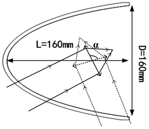
The aerodynamic performance of an ellipsoidal dome depends mainly on the length to diameter ratio. The face form of the inner surface is more or less arbitrary. To simplify the complexity of the analysis, the internal and external surfaces are set to be ellipsoidal and concentric, as shown in Fig. 1.
The radius


where
A conformal dome model is built to analyze the static and dynamic aberration properties for different FORs, as shown in Table 1. The outer surface of a conformal dome is continuous, so a conformal dome can provide an FOR far greater than a conventional spherical dome, without vignetting. We put a perfect lens 120 mm behind the dome as the imaging system. The circumrotation node is located at the center of the perfect lens; the rotation step of the gimbal is 10°, and the FOR is 100°.
[TABLE 1.] Parameters of an ellipsoidal dome
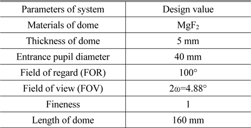
Parameters of an ellipsoidal dome
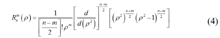
In this paper, Zernike polynomials are used to analyze the aberrations generated by an ellipsoidal dome. The mathematical expression for a Zernike polynomial is
where
[TABLE 2.] Terms Z5-Z9 of a Zernike polynomial expression
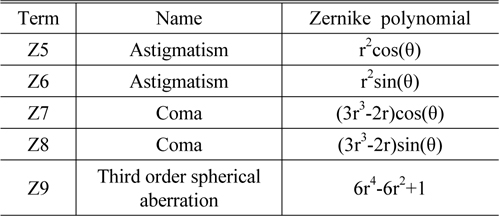
Terms Z5-Z9 of a Zernike polynomial expression
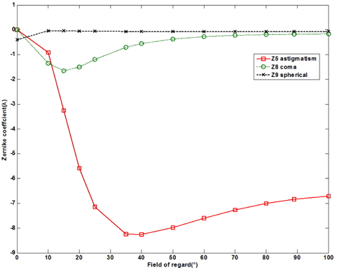
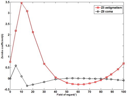
Astigmatism (Z5), coma (Z8), and spherical aberration (Z9) induced in the optical system by the dome are shown in Fig. 2. They vary with FOR. For narrow FOR, the ellipsoidal dome is similar to a sphere, while for wide FOR it loses spherical symmetry and gradually becomes similar to the structure of a cylinder, causing large coma and astigmatism. The spherical aberration stays at the level of -0.07 times the wavelength for any FOR, and can be ignored. The coma becomes most serious at 20°; when the FOR is greater than 30°, the coma is reduced to one wavelength and remains nearly constant. Compared to coma, astigmatism is more serious, especially when the FOR is greater than 30° and the value of astigmatism is nearly eight wavelengths, and varies with FOR. Thus astigmatism is the main dynamic aberration that needs to be corrected.
III. VARIABLE ASTIGMATISM CORRECTION VIA A CYLIDRICAL LENS
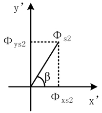
Astigmatism is generated by a difference in optical powers in the tangential and sagittal planes, resulting in two separated line foci. It is well known that cylindrical elements can be introduced to an optical system to provide single-axis power compensation, to balance the relative mismatch in focal lengths, but a fixed cylindrical lens can only provide a certain astigmatism, and cannot correct the variable astigmatism at different FORs introduced by a conformal dome. This paper puts forward the use of a rotating cylindrical lens for variable astigmatism correction. When we rotate a cylindrical lens about the optical axis, the powers along the x’ and y’ axes projected from the cylindrical lens will change. This introduces a variable astigmatism to balance the astigmatism caused by the dome at different FORs.
The underlying rationale for this correction technique is derived from the paraxial power relation for a system of two separated, thick lenses, given by Eq. (5) [9-11]:

where
Each of these power relations is separable in


where
The powers of the dome along the


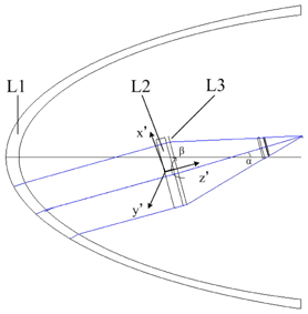
When the FOR changes, the cylindrical lens will be rotated about the Z’ axis.

To achieve this, a correction structure is put forward, as shown in Fig. 4. L1 is an ellipsoidal dome, L2 is a cylindrical lens, and L3 is a perfect lens for imaging. At different FOR, the cylindrical lens rotates
When correcting aberrations using a rotating cylindrical lens, the error function based on Zernike aberrations was found to converge rapidly and the value of the error function to be substantially reduced. The aberrations were obviously corrected. Since the error function has a few minima, the rotation angle must be appropriately adjusted according to the values and types of residual aberrations, in an optimization process. The weights of different FOR should also be appropriately distributed, according to the residual aberrations of each FOR. Sequentially, optimizing the optical system again achieves the minimal value of the error function.
Figure 5 shows the curves for the astigmatism and coma of the conformal optical system, after correction. For FOR below 30°, the residual astigmatism and coma are still more than one wavelength, but this is not encountered in a top-view optical system. For FOR over 30°, the residual aberration is less than half of a wavelength, and the fluctuation range is very small, less than 0.75 of a wavelength. Therefore, the astigmatism induced by a conformal dome is well compensated by the rotating cylindrical lens from 30° to 100°.
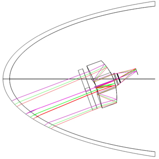
To illustrate that the rotating cylindrical lens has a better aberration correction effect, a complete cooled conformal optical system is designed by replacing the perfect lens with a solid catadioptric system. The whole conformal optical system consists of only three optical elements, as shown in Fig. 6. The optical system FOV is circular and of value 2 ω = 4.88°. The total length of the system from the apex of the dome to the image plane is 120 mm, less than the dome length. The aperture stop is placed at 19.8 mm from the image plane, and the diameter of the exit pupil is set 10.6 mm, to bring the cold aperture efficiency to 100%.
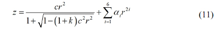
The imaging part of the system behind the dome is a solid catadioptric structure. This optical system can effectively shorten the light path and make the system more compact. To correct other aberrations, all of the surfaces are chosen to be aspherical, with a profile expressed via Eq. (11):

where
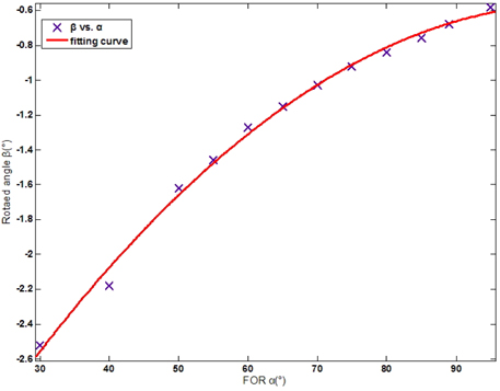
The relationship between FOR and the rotation angle of the cylindrical lensafter optimization is show in Fig. 7. The curve is smooth and easy for a servo to implement. The function after curve fitting can be written as follows:

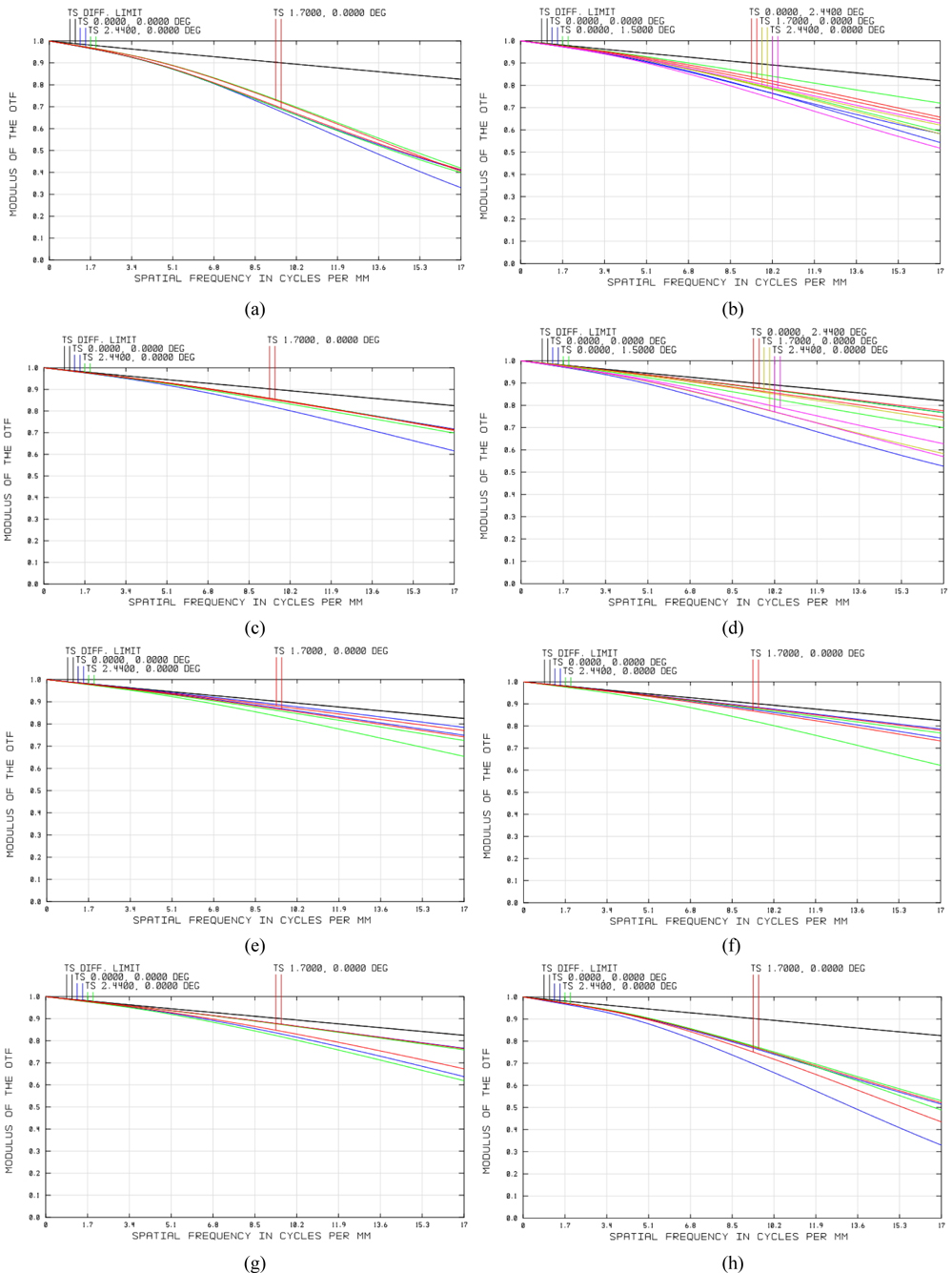
Figure 7 is the modulation transfer function (MTF) curve of the optical system for different FOR, wherein most MTF values are close to the diffraction limit, and a few are nearly 0.41 at the Nyquist frequency of 16.67 lp/mm. The optical system offers excellent image quality.
This paper has presented a conformal top-view seeker optical system based on a rotating cylindrical lens, with simple structure and excellent imaging quality. The aberration characteristics of the ellipsoidal dome were well investigated. The results showed that the Zernike aberrations introduced by the dome from 30° to 100° were decreased dramatically. Finally, an optical design with only three optical elements was presented. Compared to the traditional aberration correction method, the method presented in this paper not only improved the imaging quality, but also simplified the structure of the conformal optical system.