In this paper, we propose a power management scheme for a hybrid power system using a fuel cell (FC) and a battery. The hybrid power system consists of an FC, converters, an inverter, and a battery for driving the propulsion system of small ships. In general, an FC has limitations in terms of the energy storage, response capability, cold start, and voltage fluctuation with a peak load. To address these issues, FC-based power systems have to be combined with auxiliary energy systems such as a battery or an ultra-capacitor for improving dynamic (response) characteristics. Battery systems cannot control their charging and discharging current. In order to control the charging/discharging current, a converter needs to be installed between a DC bus and a battery.
The proposed hybrid power system has two power sources: an FC and a battery system as an auxiliary source. The battery system is connected directly in parallel to the DC bus; its function is to enhance the peak power capacity and power the load during a cold start. The FC and the battery system are connected to the same DC bus through an appropriate unidirectional converter (UDC) and bidirectional converter (BDC), respectively.
The hybrid power system operates well under various load conditions (e.g., steady, cold start, and overload). The operation of the battery system can be controlled by the battery voltage and the DC bus. The battery system is connected to the DC bus through the BDC, which can be controlled according to the voltage level. The voltage level of the battery is categorized into three types: over-discharge, normal, and over-charged. The battery system is connected to the DC bus, which is operated in either the buck mode, the boost mode, or the stop mode [1].
In this paper, we propose a hybrid power management scheme for the propulsion system of a small leisure ship, which is operated with a load variation according to the state of the sea. When the pulse load is generated, the power source supplies a considerably higher peak current than that in the case of a constant load. Once the peak load is generated, the battery is damaged by the rush current. Therefore, the power flow of the proposed hybrid power system is controlled with a BDC. Finally, the simulator for the hybrid power system was developed for analyzing the operating characteristics according to the load.
II. HYBRID POWER SYSTEM DESIGN
In this paper, we present a hybrid power system design for small ships (e.g., leisure ships and fishing boats). FCs are a promising technology used for electric power generation in ships because of their high efficiency and low carbon emission.
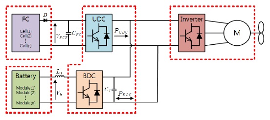
In general, the ship’s main power system is a stand-alone system where most of the power is used for propulsion. Fig. 1 shows the power system used in small ships for electric propulsion. It is composed of several parts: the generator, storage, converter, filter, and the propulsion part [2-4].
The output voltage range of an FC is very wide and depends on the load; therefore, the FC cannot directly connect to the inverter. The output voltage of an FC is selected according to the rating power.
For peak power applications, a battery is used in modules in which many submodules are connected in series and in parallel in order to obtain acceptable voltage and power. The battery terminal voltage
In FC cell of power generation system, the FC cell potential voltage

Here,
The hybrid power system has a UDC and a BDC. Normally, a UDC is required for obtaining a constant output voltage, which is the input voltage of the inverter. The input and the output currents and the voltage ripple of the UDC are small and ensure the safe operation of the FC module. The UDC has to control and condition the output power of the FC, and its electric characteristics have to match those provided by the FC and demanded by the load.
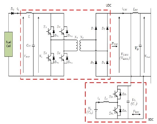
The UDC is designed with the full-bridge converter that is widely used in an FC power system. UDC can operate under a constant voltage condition and a limited current condition. Fig. 2 shows the main circuit of the power management system [5-7].
In general, the output of the UDC is connected to the DC bus, which is followed by the inverter with the output of the propulsion motor (220 VAC/60 Hz). The UDC output

Here,
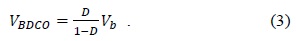
The BDC allows both directional power flows for the discharge and recharge of the energy storage. Its response needs to be sufficiently fast to compensate for the slow dynamics of the FC during startup or sudden load changes. The battery is connected in parallel to the high-voltage DC bus through the BDC, which should be controlled in a suitable mode according to the condition of the battery and the FC. The BDC connects the DC bus and the battery, and can transmit the energy in both directions. In general, a buck–boost converter is widely used as the BDC, which can work in the buck mode to charge the battery and in the boost mode to discharge the battery. The output voltage

If
In the buck mode, the output voltage of the BDC is the battery voltage
During the start period, first, the battery powers the load and the BDC works in constant voltage mode, where


Here, ∆
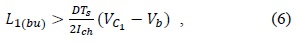
In order to ensure the continuous-condition current mode, the inductor


Further, the capacitor
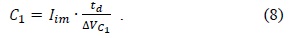
A battery can be employed in the power system as an auxiliary energy source. The choice of battery is related to the selection of the BDC. The capacity of the battery

Here,
Among the many modeling methods, the internal resistance model is used. This model can estimate the SOC using power.
Further,

The battery SOC in the steady-state
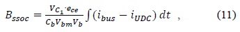
where
An inverter and a motor chosen for many industrial applications are employed in this system.
III. DC/DC CONVERTER OPERATION
In the UDC, all switches are closed at
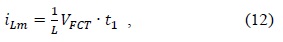
where
The difference between the inductor current
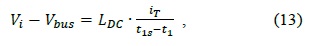

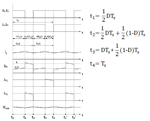
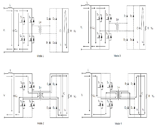
The operation of the proposed UDC shown in Fig. 2 is simplified, and all devices and components are assumed to be ideal. Fig. 3 shows the operation mode diagrams of the UDC, and one operating cycle can be divided into four modes.
Fig. 4 shows the corresponding waveforms for each mode.
1) Mode 1 Mode 3


2) Mode 2 Mode 4 (

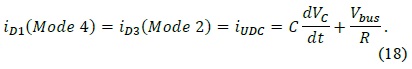
The current flows through the DC bus are shown in Fig. 5 can be expressed as follows:

The output voltages

IV. SIMULATION AND EXPERIMENTAL RESULTS
The FC is connected to the DC bus through the UDC, and the battery is connected to the DC bus through the BDC. The UDC and the BDC should operate under a suitable control according to the conditions of the FC and the battery. Table 1 shows the hybrid system operation condition.
[Table 1.] Hybrid system operation situation
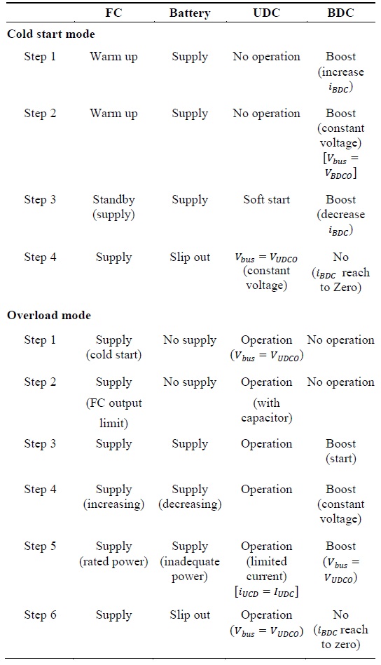
Hybrid system operation situation
The DC bus is changed by the operation condition of the FC. The working condition of the FC is defined by the FC limited power point voltage
We have to select the FC limit-power point voltage
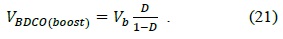
During the overload condition, the battery needs to slip into the system, and the BDC should begin to work in the boost constant-voltage mode. Further,
The FC response time is tens of seconds during the cold-start state, and hundreds of milliseconds in the standby (warm up) condition. The UDC response time is tens of microseconds. Therefore, the UDC response performance is not a serious issue in the hybrid system.
Models of the 1.5-kW fuel cell system using the BDC are obtained for each part of this study. To research the UDC, the BDC power is changed by varying the load, and the simulation is performed using LabVIEW. In the simulation, the BDC reaction rate is considered to be the maximum [14].
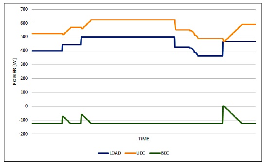
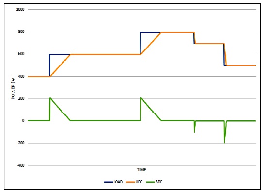
The UDC control algorithm regulates the DC bus voltage and adjusts the UDC output voltage. The fuel cell has a limitation with respect to the increase or decrease in the power. When the load increases sharply, the UDC power increases at a constant rate. Consequently, the UDC power handles the entire load. Further, the UDC power shows a similar trend for a decreasing load.
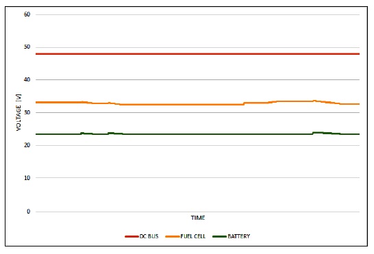
The BDC control algorithm is different for the two modes. The current travels from the battery to the DC bus in the boost mode, and from the DC bus to the battery in the buck mode. The boost mode algorithm regulates the DC bus voltage and adjusts the BDC output voltage. When the load increases sharply, the BDC power increases rapidly. If the increase in the load is greater than that in the BDC power, the BDC is switched to the boost mode, as shown in Figs. 5 and 6.
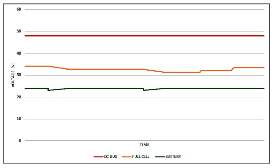
The buck mode algorithm is used when there are no sudden increases in the load. If the load increases sharply in the buck mode, the BDC output voltage decreases, leading to a drop in the battery charging current. In the event of a regenerative current, the BDC mode switches to the buck mode, as shown in Figs. 7 and 8 and returns to the boost mode shortly.
The use of the BDC system has many advantages. First, the battery charging current can be selected. Second, the volume of the battery pack can be optimized by adjusting the battery charging or discharging current. Third, frequent charging and discharging of the battery is prevented by adjusting the BDC switching time. This can be expected to increase the battery life. However, switching devices improvement in high power system is need to use BDC with safety operation. This problem can be solved with technological advances in the near future.