Signal distortion due to chromatic dispersion and the nonlinearity of optical fibers is a fundamental barrier to the increase in the data capacity and the transmission length of optical communication systems [1,2]. Thus, optical techniques to compensate for the impairments due to group velocity dispersion (GVD) and fiber nonlinearities in fiber optic systems have attracted significant attention [3]. Dispersion management (DM) using dispersion-compensating fibers (DCFs) has the capability to offset the GVD effects of transmission fibers, such as the single-mode fibers (SMFs). A dispersion-managed optical link is designed to achieve low (or even zero) path-averaged GVD by the periodic alternation of the sign of the dispersion along an optical line that dramatically reduces pulse broadening [4]. If nonlinearity is neglected, it would be possible to transmit optical pulses through a DM system without significant distortion. Further, the DM technology supports the transmission of a return-to-zero (RZ) pulse stream combined with the dense-wavelength-division multiplexing (DWDM) technique [5,6].
Further, optical phase conjugation is an alternative approach used for overcoming or mitigating the effects of GVD and SPM [7-9]. By optically conjugating the phase of a signal in the middle of a total transmission link, impairments that occurred in the former transmission section of the total transmission link (before conjugation) can be cancelled by impairments that occur in the latter transmission section of the total transmission link (after conjugation) [10]. However, the nonlinear compensation through optical phase conjugation (OPC) was found to be limited in non-pseudo-linear systems because of the asymmetric signal-power evolution, large amplifier spacing, and long transmission distance [11]. Furthermore, the application of the midway OPC to a wavelength-division multiplexed (WDM) system is more difficult, because if perfect dispersion compensation is accomplished for a particular channel of the WDM system, other wavelength channels may encounter different amounts of cumulative dispersion proportional to their wavelength separations from the zero-average-dispersion wavelength channel [12].
Fortunately, various techniques, such as optimization of the OPC position [13,14] or combination of the DM technology [11,15,16], have been proposed recently. Nevertheless, optical link configurations with the combination of DM and optical phase conjugation are still symmetrical with respect to the OPC position, because of the appropriate symmetry of OPC. That is, the number of fiber spans, the length of a fiber span, and the length of SMF in the former transmission section before the OPC are the same as those in the latter transmission section after the OPC. Further, the OPC position is unlimited for a reconfigurable optical link with large amplifier spacing (i.e., long fiber span length).
To the best of my knowledge, an analysis of the effect of the OPC positions on the compensation for the distorted WDM channels has not been reported thus far. Therefore, in this study, non-midway OPC to compensate for the distorted 24-channel × 40-Gbps WDM signals in an optical link with 30 fiber spans consisting of 80-km SMF and the appropriate length of DCF to complete the inline (i.e., one fiber span) dispersion compensation is demonstrated.
The rest of this paper is organized as follows: Section II introduces the modeling and the specifications of the proposed optical transmission links. The 24-channel × 40-Gbps WDM systems and the numerical assessment method are also described in this section. In Section III, the simulation results and the related analysis are presented. Further, the conclusion is presented in Section IV.
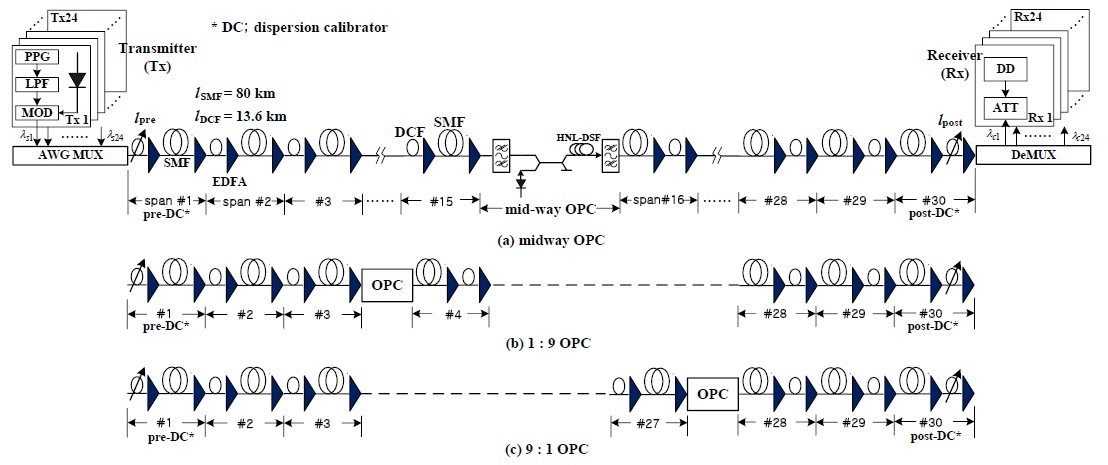
In this study, compensation for the distorted 24-channel WDM signal by applying non-midway OPC to a DM link is confirmed by investigating the compensation effect depending on the deployment of the SMFs and the DCFs in the fiber span, as shown in Figs. 1 and 2. This is so because the performance of an optical system depends on the position of the DCF [17] and on the amount of residual dispersion [18,19]. From the viewpoint of the position of the DCF, the dispersion compensation scheme is divided into pre- and postcompensation where the DCF is located before and after the SMF in every fiber span, respectively. In the case of the DM applied to every fiber span (i.e., inline DM), residual dispersion per span (RDPS) is defined as the dispersion accumulated in each fiber span, while the net residual dispersion (NRD) is defined as the total dispersion accumulated at the end of the transmission link.
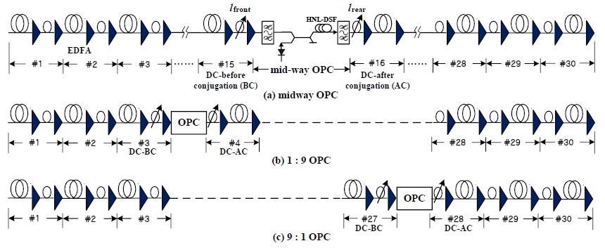
The optical link configurations considered in this study are classified into the precompensation–OPC–postcompensation scheme (Fig. 1) and the postcompensation–OPC–precompensation scheme (Fig. 2), for the determination of the local dispersion symmetry with respect to the OPC. The total transmission link consists of 30 fiber spans in both the configurations. The number of the former transmission sections (FTSs) and that of the latter transmission sections (LTSs) are 15 in the midway OPC link, as shown in Figs. 1(a) and 2(a). Besides midway OPC, the various non-midway OPC positions, such as 1:9 (3 fiber spans − OPC − 27 fiber spans, as shown in Figs. 1(b) and 2(b)), 2:8, 3:7, 4;6, 6:4, 7:3, 8:2, and 9:1 (as shown in Figs. 1(c) and 2(c)) schemes are represented as “FTS versus LTS.”
The length of the SMF in every configuration,
The NRD is also 0 ps/nm because RDPS = 0 ps/nm. However, it has been reported that the optimal NRD in a “pseudo-linear” system might not be 0 ps/nm [20]. Thus, we need to estimate the optimal NRD of each link configuration and to apply the induced optimal NRD to each link. The DCFs of the first fiber span and the last fiber span in the precompensation–OPC–postcompensation scheme (Fig. 1) play the role of the calibrator of each transmission section’s NRD. Further, the DCFs of the fiber span before OPC and the fiber span after OPC in the postcompensation–OPC–precompensation scheme (Fig. 2) play the role of the calibrator of each transmission section’s NRD. That is,
For the simplicity of the numerical simulation procedures, the detailed NRD calibration is designed using the following basic concept: 1) The NRD of the entire transmission link is determined by the NRD of one transmission section, and simultaneously, 2) the NRD of the rest of the transmission sections is zero (that is, complete dispersion compensation is presented in the rest of the transmission sections). The case of
>
B. WDM System and Numerical Assessment
The transmitter (Tx) for the 24-channel WDM system shown in Fig. 1 is assumed to be a distributed feedback laser diode (DFB–LD). The center wavelength of the DFB–LD is assumed to be 1550–1568.4 nm with a spacing of 100 GHz (0.8 nm) on the basis of ITU-T Recommendation G.694.1. The DFB–LD is externally modulated by an independent 40-Gbps 127 (=27 − 1) pseudo-random bit sequence (PRBS). The modulation format from the external optical modulator is assumed to be RZ. Further, the output electric field of the RZ format is assumed to be a second-order super-Gaussian pulse with a 10-dB extinction ratio (ER) and a duty cycle of 0.5, and is chirp-free.
The optical signals propagating through the FTS are converted into conjugated signals with wavelengths of 1549.5‒1528.5 nm by the midway OPC. The 3-dB bandwidth of the conversion efficiency is calculated to be approximately 48 nm (1526‒1574 nm) from the previously mentioned OPC parameters [16]. Thus, all the signal wavelengths and these conjugated wavelengths belong within the 3-dB bandwidth of the conversion efficiency. The receiver (Rx) consists of an EDFA pre-amplifier with a 5-dB noise figure, an optical filter of 1-nm bandwidth, a PIN diode, a pulse shaping filter (Butterworth filter), and the decision circuit. The receiver bandwidth is assumed to be 0.65 × bit rate [5].
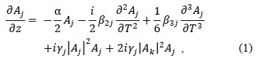
The propagation of the signal in a lossy, dispersive, and nonlinear medium can be expressed by the nonlinear Schrodinger equation (NLSE), assuming a slowly varying envelope approximation:

where
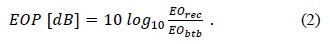
The eye-opening penalty (EOP) is used for assessing the system performance of the receiving WDM signals in this work, as shown in the following equation:

where
III. SIMULATION AND DISCUSSIONS
Fig. 3 illustrates the EOPs of the worst channel among the 24 WDM channels as a function of the NRD controlled by pre-DC, post-DC, DC-BC, and DC-AC in several non-midway OPC simulations and the midway OPC simulations. It is confirmed that optimal NRDs were found to be 10 ps/nm or −10 ps/nm, depending on the NRD control methods and the OPC positions. The results obtained from Fig. 3 show that the optimal NRDs were 10 ps/nm or −10 ps/nm; these results are remarkably consistent with the results reported in [20], which is a study dealing with a “pseudo-linear” system.
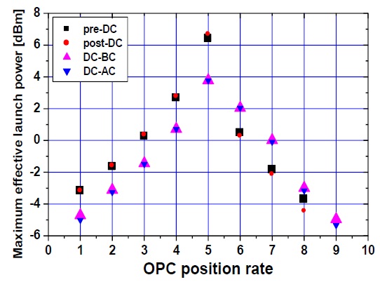
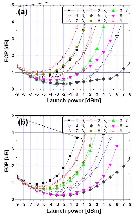
Fig. 4(a) and (b) illustrate the EOPs of the worst channel as a function of the launch power in the optical links with the optimal NRD of 10 ps/nm or −10 ps/nm for pre-DC and DC-BC, respectively. In fiber communication systems, a 1-dB EOP is used as the system performance criterion, which is equivalent to the pulse broadening (the ratio of the received pulse RMS width to the initial pulse RMS width) of 1.25 and corresponds to a bit error rate (BER) of 10−12 [21]. Therefore, we define the launch power results for EOP of <1 dB as the effective launch power. Fig. 5 shows the maximum effective launch power for four NRD calibration methods as a function of the OPC position ratio; here, the x-axis represents the ratio of the number of FTS to the number of the total transmission links. We first confirmed that the decrease in the maximum effective launch power increases with an increase in the deviation of the OPC position from the midway in all the considered optical links. However, for the non-midway OPC schemes, the maximum effective launch powers in the optical links with the optimal NRD controlled by pre-DC and post-DC are better than in those controlled by DC-BC and DC-AC in the OPC placed at the position ratio of <4. On the other hand, the maximum effective launch powers in the optical links with the optimal NRD controlled by DC-BC and DC-AC are better than in those controlled by pre-DC and post-DC in the OPC placed at the position ratio of >6. That is, pre-DC and post-DC are more advantageous for controlling the optimal NRD and consequently, for compensating the distorted WDM channels in the optical links of the OPC position closer to Tx. However, DC-BC and DC-AC are more advantageous in the optical links of the OPC position closer to Rx.
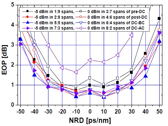
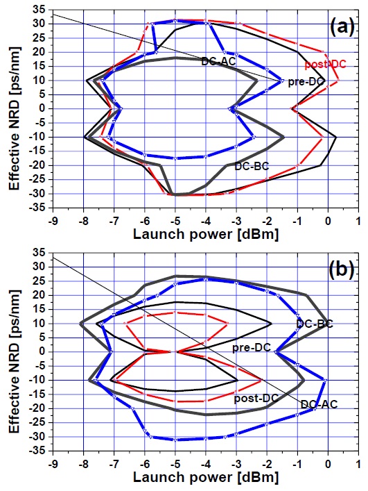
Through the analysis of the results shown in Fig. 3, it is also confirmed that the NRD inducing the EOP of <1 dB at an arbitrary launch power in each optical link is distributed over a wide range. These NRD values result in the EOP of <1 dB and are defined as the effective NRD range (i.e., the effective NRD contour). Fig. 6(a) and (b) illustrate the effective NRD ranges depending on the launch power of the worst channel and the four NRD control methods in the case of the optical links with the non-midway OPC placed at 3:7 and 7:3, respectively. As shown in Fig. 5, the effective NRD ranges controlled by pre-DC and post-DC are better than those controlled by DC-BC and DC-AC in the optical links of the 3:7 configuration. However, the effective NRD ranges controlled by DC-BC and DC-AC are better than those controlled by pre-DC and post-DC in the optical links of the 7:3 configuration.
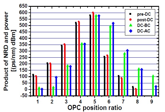
The effective NRD contours of the rest of the non-midway OPC configurations are not shown in this paper. Therefore, we need to quantitatively analyze the factors for an easy comparison of the effective NRD ranges affected by the NRD control methods and the OPC positions. We use the area of the contour from the results shown in Fig. 7 as a quantitative factor. The area of the contour is defined as the product of the NRD and the (launch) power; this is plotted in Fig. 7 as a function of the OPC position ratio and the NRD control methods. The products of the power and the NRD controlled by pre-DC and post-DC in the optical links with the non-midway OPC placed at the 9:1 position are not plotted in Fig. 7, because these cannot be obtained; that is, no NRD should result in an EOP of <1 dB in the optical link of the 9:1 configuration. From the result shown in Fig. 7, we confirmed that, as in the case of the previous results, pre-DC and post-DC are more advantageous for obtaining a relatively large product of the NRD and the power, and consequently, for compensating for the distorted WDM channels with a higher launch power through a wider NRD range in the optical links of the OPC position closer to Tx. However, DC-BC and DC-AC are more advantageous for obtaining a larger product of the NRD and the power in the optical links of the OPC position closer to Rx.
The simulations described in this paper were conducted for investigating the possibility of implementing a flexible optical link configuration using non-midway OPC applied to complete inline dispersion-managed links. It was confirmed that although the compensation by using the non-midway OPC for the distorted WDM channels is less effective than that by using the midway OPC, the compensation effect in the non-midway OPC links can be further improved by deploying SMFs and DCFs consisting of fiber spans. That is, when the non-midway OPC is placed at positions closer to Tx, the deployment of precompensation (i.e., the sequence of DCF+SMF)–OPC–postcompensation (i.e., the sequence of SMF+DCF) is more advantageous for the compensation. However, the inverse deployment with respect to OPC (i.e., postcompensation–OPC–precompensation) is more advantageous when the non-midway OPC is placed at positions closer to Rx. Further, the wide NRD margin for the good compensation (EOP ≤1 dB) is obtained by using pre-DC or post-DC when the non-midway OPC is placed at positions closer to Tx, and by using DC-BC or DC-AC when the non-midway OPC is placed at positions closer to Rx.