Group-velocity dispersion (GVD) and nonlinearity of optical fibers are two major factors limiting the high bit rate and length (BL) product in optical communication systems [1,2]. Dispersion management (DM) is a very effective technology in ultrafast high-bit-rate optical communication lines, if nonlinearity is neglected. A dispersion-managed optical fiber is designed to achieve low (or even zero) path-averaged GVD by using a periodic chain of spans, that is, by inserting the dispersion compensating fiber (DCF) with anomalous GVD into a single-mode fiber (SMF) with normal GVD [3-5].
Besides DM technology, optical phase conjugation is an alternative approach to mitigate the GVD effect and the nonlinearity effects; in particular, this approach is more effective in compensating for the distorted optical signals due to the interaction of the GVD and the self-phase modulation (SPM) among nonlinearities [6-8]. The com-pensation for signal impairment in this technique is theoretically possible through the use of an optical phase conjugator (OPC) in the middle of the entire transmission line. The phase-conjugated signal generated by the OPC carries the same data as the original signal, but the sig¬nal spectrum is inverted to compensate for the optical pulse distortion.
However, DM and optical phase conjugation have certain limitations, such as less compensation for the optical signal distortion due to nonlinear effects in only DM, and the practical difficulty of the symmetry of the dispersion distribution and the strength of the optical power distri-bution along the fiber with respect to the position of the OPC [8]. Fortunately, a combination of DM and OPC has been recently proposed for overcoming these problems [9-12].
In the optical link with a combination of DM and optical phase conjugation, the compensation for the signal distortions depends upon the equalities of the fiber span parameters, such as the SMF length, the DCF length, the dispersion coefficient of DCF, and the residual dispersion per span (RDPS), between the former half-transmission section (before OPC) and the latter half-transmission section (after OPC) [3-5,13]. In particular, in the case of a wavelength-division multiplexing (WDM) system, it is difficult to find the best link condition determined by the above-mentioned parameters. This is attributed to the fact that if perfect dispersion compensation is accomplished for a particular channel of the WDM system, other wavelength channels may encounter different amounts of cumulative dispersion proportional to their wavelength separations from the zero-average-dispersion wavelength channel [14,15].
Thus far, most works have focused only on either the DM techniques or the combined DM and OPC techniques for uniformly deployed optical links by equalizing the fiber span parameters in the former half section with those in the latter half section. This uniform link configuration makes the optical link design simple, but the implementation of a reconfigurable optical link is very difficult. To the best of the author’s knowledge, the performance assessments of a DM and OPC-combined link with the fiber span parameters in both half sections are not equal to each other and are yet to be reported.
Therefore, in this paper, we propose a new optical link scheme having the capability to flexibly implement optical link configurations. The SMF lengths of 80 km and 112 km are used in the proposed optical link, but the total lengths of the former half section and of the latter half section are the same. Therefore, we call this link scheme “pseudo-sym-metric configuration,” wherein the SMF lengths are uniform for all fiber spans and the total lengths of both half sections are consistent in a “symmetric configuration.”
II. WDM TRANSMISSION MODELING AND NUMERICAL ASSESSMENT METHOD
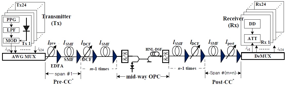
The optical transmission link shown in Fig. 1 consists of
It is assumed to be
[Table 1.] Optical link parameters
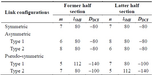
Optical link parameters
The fiber parameters, except the SMF length (
RDPSs of all fiber spans, except the first and the last fiber spans, are varied from 0 ps/nm to 1350 ps/nm (50 ps/nm intervals) or 0 ps/nm to 1330 ps/nm (70 ps/nm intervals) by controlling
Because most fiber spans have arbitrary RDPS, the net residual dispersion (NRD) of each half section is not zero, but very large, except for RDPS = 0 ps/nm. Thus, we need to control the NRD of each half section by using the arbitrary span in order to obtain the optimal value for good compensation. The DCF lengths of the first fiber span and the last fiber span, i.e.,
In this paper, the optical link configurations are designed on the basis of the following concepts. 1) The precompensation (i.e., DCF + SMF) in the former half section and the postcompensation (i.e., SMF + DCF) in the latter half section are considered for an effective symmetric distribution of local dispersion with respect to OPC. 2) The NRD of the entire transmission link is determined through two concentrated places as follows: first, the entire NRD is controlled by only
The transmitter (Tx) for the 24-channel WDM shown in Fig. 1 is assumed to be a distributed feedback laser diode (DFB-LD). The center wavelengths of the DFB-LDs are assumed to be 1550–1568.4 nm (0.8 nm interval, i.e., 100 GHz interval) on the basis of ITU-T recommendation G.694.1. DFB-LDs are externally modulated by an inde-pendent 40-Gbps 127 (=27 – 1)-pseudo-random-bit sequence. The modulation formats from the external optical modulators are assumed to be return-to-zero (RZ), while the output electric field of the RZ format is assumed to be a second-order super-Gaussian pulse with a 10-dB extinction ratio and 0.5 duty cycle, and is chirp free.
The nonlinear medium of the midway OPC illustrated in Fig. 1 is assumed to be the highly nonlinear dispersion-shifted fiber (HNL-DSF). The parameters of the OPC are as follows: loss of HNL-DSF
The optical signals propagating through the former half section are converted to the conjugated signals with wavelengths of 1549.5–1528.5 nm by the midway OPC. The 3-dB bandwidth of the conversion efficiency is calculated to be almost 48 nm (1526–1574 nm) from the previously mentioned OPC parameters. Thus, all the signal wavelengths and the conjugated wavelengths belong within the 3-dB bandwidth of the conversion efficiency.
The receiver (Rx) consists of the pre-amplifier of the EDFA with a 5-dB noise figure, an optical filter of 1-nm bandwidth, PIN diode, pulse shaping filter (Butterworth filter), and the decision circuit. The receiver bandwidth is assumed to be 0.65 times the bit rate [16].
The propagation of a signal in a lossy, dispersive, and nonlinear medium can be expressed by the nonlinear Schrödinger equation assuming a slowly varying envelope approximation. The numerical approach of (1) is completed by using the split-step Fourier (SSF) method [17].
The eye-opening penalty (EOP) is used for assessing the system performance of the receiving WDM signals in this work, as follows:
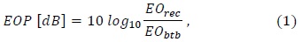
where
III. SIMULATION AND DISCUSSIONS
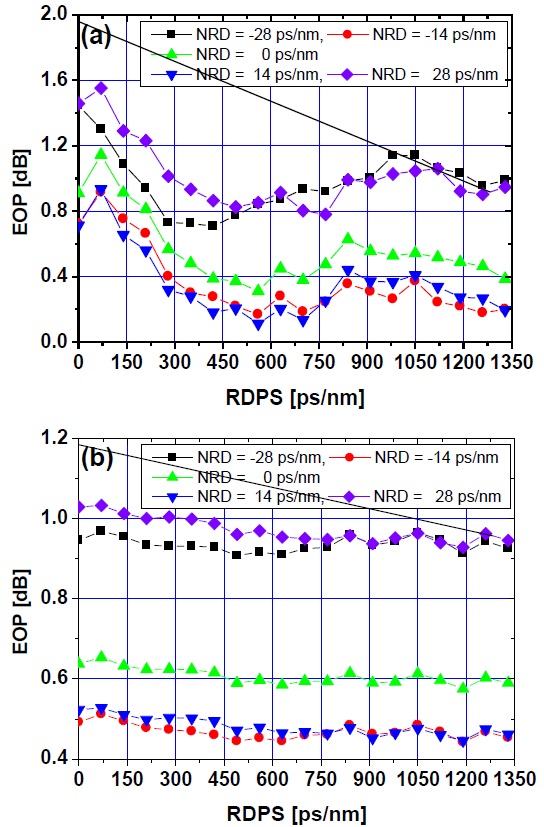
Fig. 2(a) and (b) show the EOPs of the worst channel among the 24 WDM channels as a function of RDPSs at several NRDs in the proposed pseudo-symmetric link configurations of type 1 and type 2, respectively. The results shown in Fig. 3(a) are obtained when the launch power is –3 dBm and the NRDs are controlled by pre-CC. Further, the results shown in Fig. 3(b) are obtained when the launch power is –5 dBm and the NRDs are controlled by post-CC.
In both cases, we confirmed that the EOP characteristics over the entire RDPS range when NRD = 14 ps/nm or –14 ps/nm are superior to those for other NRD values. These two NRD values correspond to a 0.1 km or –0.1 km displacement from the positions of the first DCF or the last DCF for NRD = 0 ps/nm. That is, the optimal NRD values are obtained to make the lengths of the first DCF or the last DCF shorter or longer by 0.1 km as compared to the lengths obtained when NRD = 0 ps/nm. The optimal NRD values in the rest link configurations are obtained and are the same as the results shown in Fig. 2. That is, the optimal NRD values are 8 (or –8) ps/nm and 10 (or –10) ps/nm in the link configurations with
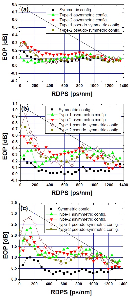
Fig. 3 shows the EOPs of the worst channel as a function of the RDPS values at several launch powers (i.e., –1, 3, and 7 dBm) in five optical link configurations with the optimal NRD, which was obtained using the same method as that used for obtaining the results shown in Fig. 2. We first confirmed that the best link configuration is symmetric because the EOPs over the entire RDPS range are smaller than those in the case of the other configurations, which is irrelevant for the considered launch powers. This result can be attributed to the fact that the symmetric configuration is the best stable deployment of fibers.
However, the most significant result shown in Fig. 3 is that the improvement in the EOP characteristics in the pseudo-symmetric configurations is better than that in the asymmetric configurations, if the RDPSs are restricted to 500–800 ps/nm. The results shown in Fig. 3 imply that even though the compensation in the case of the pseudo-symmetric configurations of the optical fiber parameters is less effective than that in the case of a conventionally symmetric configuration. Further, a flexible link imple-mentation using the different lengths of the SMF and the different coefficients of the DCF with respect to OPC is possible within the restricted range of RDPS.
Another significant result shown in Fig. 3 is that there are no significant differences between the EOPs in all the link configurations, if the RDPS between the adjacent fiber spans is set to be very large (i.e., 1320 ps/nm or 1330 ps/nm). This result may be attributed to the fact that, in optical links with large RDPSs, the WDM pulse widths expand significantly, and thus, the peak powers are drastically suppressed, which in turn mitigate the non-linearity effects. Further, this phenomenon is not affected by the link configurations and the launch power.
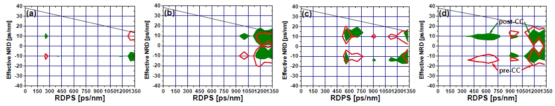
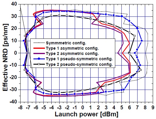
In fiber communication systems, 1-dB EOP is used as the system performance criterion, which is equivalent to the pulse broadening (the ratio of the received pulse RMS width to the initial pulse RMS width) of 1.25 and corresponds to a bit error rate (BER) of 10–12 [18]. Fig. 4 illustrates the worst channel’s effective NRD ranges as a function of RDPS (in other words, the contours of RDPS versus NRD), which results in EOPs of less than 1 dB, in two types of asymmetrically configured and two types of pseudo-symmetrically configured optical links transmitting a launch power of 7 dBm. By using the results shown in Fig. 4, we can obtain an EOP of less than 1 dB for the arbitrary RDPS, if the NRD within the contours is selected.
We first confirmed that the effective NRD ranges in two types of pseudo-symmetric configurations are superior to those in two types of asymmetric configurations, as the effective NRD ranges appear in various RDPSs and these inner areas of the contours are wider. Simultaneously, we confirmed that, in RDPSs ranging from 450 ps/nm to 800 ps/nm, there were no effective NRD ranges in both types of asymmetrically configured optical links. On the other hand, although the effective NRD ranges are narrow, these are presented in both types of pseudo-symmetrically configured optical links. Of course, these results are expected on the basis of the results shown in Fig. 3.
Fig. 5 illustrates the worst channel’s effective NRD ranges as a function of the launch power in five link confi-gurations with RDPS = 560 ps/nm and NRDs controlled by post-CC. As one might predict from the previous results, the improvement in the effective NRD ranges over a wide range of launch power in both types of pseudo-symmetrically configured optical links is better than that in asymmetrically configured optical links, but the aspects in the case of small RDPSs and large RDPSs change, although these results are not shown graphically.
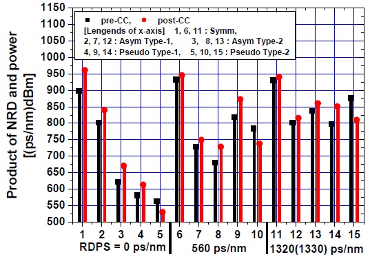
We need to use other quantitative factors for a com-parison of the effective NRD ranges depending upon the launch power in every link configuration. Thus, the contour area obtained from the results shown in Fig. 5 is used as the quantitative factor. We defined the contour area as a “product of the NRD and the (launch) power,” and this is plotted in Fig. 6.
We first confirmed that better improvement in the compensation effects is achieved by using post-CC than by using pre-CC in four link configurations for all the considered RDPS values, except the pseudo-symmetric type-2 configuration. We also confirmed that, as illustrated by the previous results, if the RDPS is selected to be large (1320 ps/nm or 1330 ps/nm, as in Fig. 6), the differences in compensation between optical link configurations are not large.
From the viewpoint of the product of the NRD and the power, a significant result shown in Fig. 6 is that the effects of the proposed pseudo-symmetrical configurations for the flexible implementation of optical links is greater in an optical link with a medium RDPS (i.e., 560 ps/nm in Fig. 6) than with a large RDPS.
The simulations described in this paper were aimed at investigating the implementation possibility of the flexible optical links by using the pseudo-symmetric configurations of the SMF lengths and the coefficients of DCF in the optical links with DM and the midway OPC. We first confirmed that the proposed pseudo-symmetrical distri-butions of the fiber spans are effective for implementing a flexible optical link in the RDPS ranges of 450 ps/nm to 800 ps/nm, because the improvement in system performance in these configurations is better than that in asymmetrically configured optical links.
We also confirmed that a large RDPS is required to obtain a system performance that is less affected by the optical link configurations. Further, we confirmed that the best NRD control method for obtaining improved system performance is post-CC and not pre-CC, irrespective of the RDPSs and the optical link configurations.