Batteries are used in many electronic devices as an energy source, but there are half a billion wasted batteries each year. Serious environmental damage is caused by leaking chemical ingredients. Therefore, we designed a wireless power rechargeable battery charging system to address the problem of wasted. Because the rechargeable batteries have cylindrical shape, they can be rolled easily. Thus, angular misalignment, which decreases the efficiency of wireless power transfer systems [1, 2]. As discussed in [3], the efficiency of wireless power transfer systems depends on a coupling coefficient and the quality factor of coil. The coupling coefficient represents the measurement of the degree of magnetic coupling, determined by coil sizes and geometric spacing. When the coils align perfectly, their coupling is the strongest. However, rechargeable batteries are difficult to align in practical situation because of the cylindrical shape. Thus, wireless power transfer system, which maintains constant coupling coefficient without sensitivity to charging conditions, is needed. Therefore, in this paper, presents system intended to lessen the variations in the coupling between transmitting and receiving coils under misalignment.
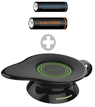
Angular misalignment occurs when receiving coil was tilted at angle between receiving and transmitting coils. Conventional planner coils cannot have magnetic fields in all directions (x, y, z) at one point because of limitations in geometrical plane forms. Therefore, receiving coil structure, which is . of two perpendicular windings, is proposed. The structure can decrease variations in coupling under angular misalignment. For validation, the wireless rechargeable battery charging system using receiving coils . of orthogonally-placed windings is proposed to charge AAA rechargeable battery (Fig. 1). Because the volume of the receiver (circuits and coil) should be small and simple, we designed the module suitable for AAA battery.
The remains of this paper is organized as follows. Section II analyzes the coil structure of proposed system about variation of mutual inductance. Then, in Section III, we present the design of the transmitter and receiver and presents the measured results. Finally, this paper concludes with a short summary in Section IV.
II. ANALYSIS THE COIL STRUCTURE OF PROPOSED SYSTEM
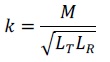
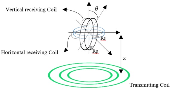
Fig. 2 shows the proposed receiving coil structure . of two coils: a vertical coil and horizontal coil. The coupling coefficient provides the measurement of the degree of magnetic coupling, which is the function of mutual coupling and defined by,

where
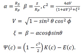
where

and as shown Fig. 2,
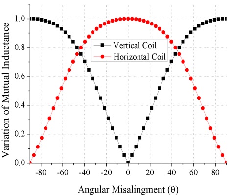
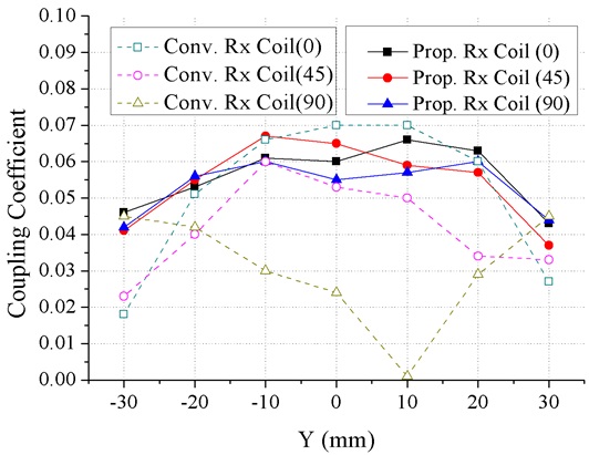
Fig. 3 shows the variation of mutual inductance verses angular misalignment at
III. IMPLEMENTATION AND MEASUREMENT RESULTS
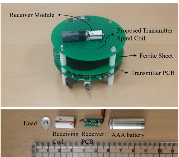
Fig. 4 shows the implemented structure of the proposed system for an AAA rechargeable battery operating at 6.78 MHz. The transmitter is . of a class-D amplifier, pre-regulator, micro-control unit (MCU), and transmitting coil. To block the magnetic field effecting to power amplifier, a ferrite sheet was inserted between the transmitting coil and power amplifier. The receiver is . of a full-bridge rectifier, buck converter, and receiving coil. The transmitting coil and receiving coil were printed on FR4 (thickness 0.8 mm, relative permittivity 4.6, tangent loss 0.015). The transmitting coil has a 32-mm radius, an inductance of 1.25 μH, and the equivalent series resistance of 0.39. The receiving coil has an inductance of 1.01 μH, the equivalent series resistance of 0.33, and vertical coil and horizontal coil with seven turns. The receiver module was designed and assembled as shown in Fig. 4. In order to easily wind up the receiving coil, the furrow of the receiver module was cut and then, receiver PCB was inserted into module to reduce the volume, and it was connected to the head and battery.
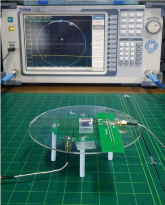
Fig. 5 shows the experiment environment. Mutual inductance was measured by
We proposed a wireless rechargeable battery charging system using a perpendicular receiving coil operating at 6.78 MHz. The misalignment critical decreased the efficiency of the wireless power transfer system. Batteries can be easily roll because of its shapes. Therefore, we proposed a receiving coil . of two orthogonal coils. Consequently, the proposed system reduced the degree of variation of the coupling coefficient against angular misalignment and charged the receiver to up to 120 mA at 1.4 V and it has about 11% overall total system efficiency. In other words, the proposed free-positioning WPC system is robust to misalignment, and this application system can be easily used for the other kinds of batteries with cylindrical structures such as AA, C, and D type.