Recent advances in ambient radiofrequency (RF) backscatter communication have enabled the development of ultra-low power or batteryless wireless connectivity of Internet of Things (IoT) devices [1, 2]. For example, Bluetooth signals can be generated using ambient RF backscatter technology [3]. However, ambient RF energy has a relatively low power density range of 0.0002–1 uW/cm2. Therefore, ambient RF backscatter devices must depend on a relatively large array antenna to fully use weak ambient RF power. By contrast, solar power has a high power density of 100 mW/cm2 during daytime [4]. Various lighting infrastructures, including white LEDs, have been widely deployed for illumination purposes. Therefore, using visible light rather than RF waves as backscatter communication media is logical.
To date, many researchers have used visible light as the communication media in IoT devices [5-7], which can be categorized into two types, depending on the direction of the communication link between the LED infrastructure and the IoT device. Most studies have used only a one-directional link (downlink) from the LED infrastructure to the IoT device; this type is called visible light communication (VLC). As VLC has no uplink capacity, it must use a separate communication link, such as Bluetooth, to receive information from IoT devices with no LED source. Unfortunately, doing so involves additional cost and system complexity. Only a few studies have used bidirectional links (uplink and downlink) between the LED infrastructure and IoT devices. In particular, the authors in [6] suggested the innovative retro-VLC concept, which uses retroreflective fabric to bounce incident light backscatter to form visible light for the uplink. However, this method requires a dedicated visible light source. To the best of our knowledge, no studies have been conducted on ambient light backscatter communication in which only ambient light is used as the illumination source.
In this paper, we propose the concept of an ambient light backscatter communication design that enables IoT devices to communicate with nearby smart devices using only backscattering ambient light emitted from a distant lighting infrastructure or available sunlight. The IoT device can selectively modulate ambient light by switching a liquid crystal display (LCD) shutter located on its surface. Then, the nearby smart device, which includes a photodiode (PD) or a camera, can demodulate this backscattered light information.
II. PRINCIPLE OF AMBIENT LIGHT BACKSCATTER
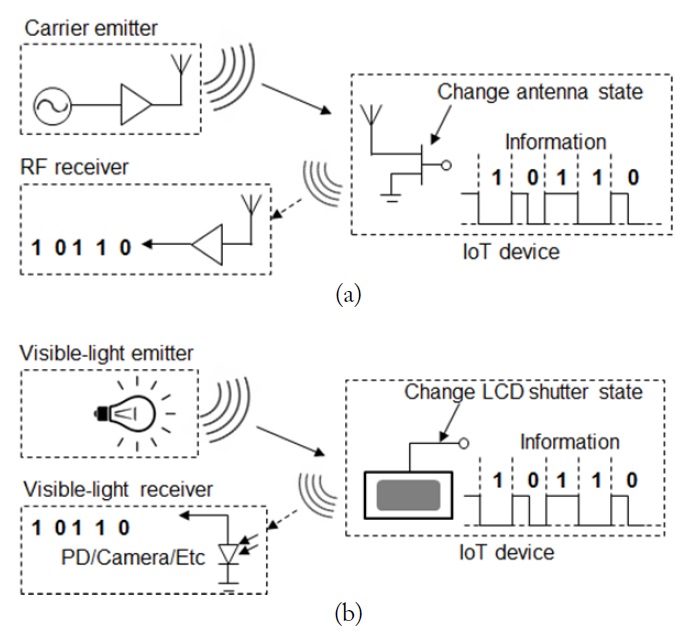
Fig. 1 shows the operating principle of ambient light backscatter in comparison with that of ambient RF backscatter. In principle, ambient light backscatter is similar to ambient RF backscatter, with the only difference being that the former deals with visible light rather than RF waves. However, the medium of visible light has many differences in the way it is implemented.
In general, ambient RF backscatter involves three different entities: a carrier emitter, an IoT device, and an RF receiver. In the IoT device, backscattering is achieved by changing the impedance of an antenna in the presence of an incident RF signal from the carrier emitter. The amount of reflection is typically determined by the difference in impedance values. By modulating the RF impedance at the port of the antenna, the amount of incident RF energy that is scattered can be modulated, thus enabling the transmission of information.
Similarly, as shown in Fig. 1(b), ambient light backscatter systems consist of a distant ambient light source, IoT devices, and receiving devices. An IoT device consists of an LCD shutter and a transmission logic circuit. For ambient light communication, the microprocessor in the IoT device selectively switches the LCD shutter to backscatter ambient light. This weak backscattered signal is then amplified, digitized, and finally demodulated in the visible light receiver of a PD, a camera, or a solar cell.
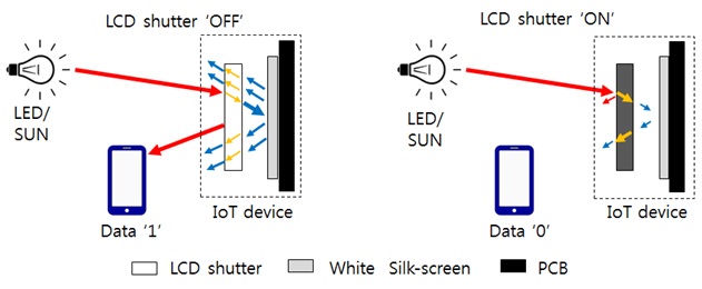
Fig. 2 illustrates the backscattering difference as a function of the LCD shutter switching state. If the LCD shutter is ON, the incident light (red line) will mostly be absorbed on the LCD shutter surface (black) and thus no visible light will go to the receiver. If the LCD shutter is OFF, the incident light will be split between reflected and transmitted light. The transmitted light is backscattered by a white silkscreen on the printed circuit board (PCB) surface. As a result, the total reflected and backscattered light is received by the nearby optical receiver of a smartphone.
Ambient light backscatter takes advantage of the existing lighting infrastructure. Accordingly, it does not require the deployment of a special-purpose power infrastructure (e.g., an RFID reader) to transmit a high-power (in a typical 4 W effective isotropic radiated power) RF signal to target devices. It can also provide a highly secure link between a user’s smartphone and IoT devices. Thus, users can easily adopt the ambient light backscatter concept. Moreover, with respect to usability, the PD is located at the back of a smartphone, and it enables the screen to display real-time information on its interaction with a specific IoT device.
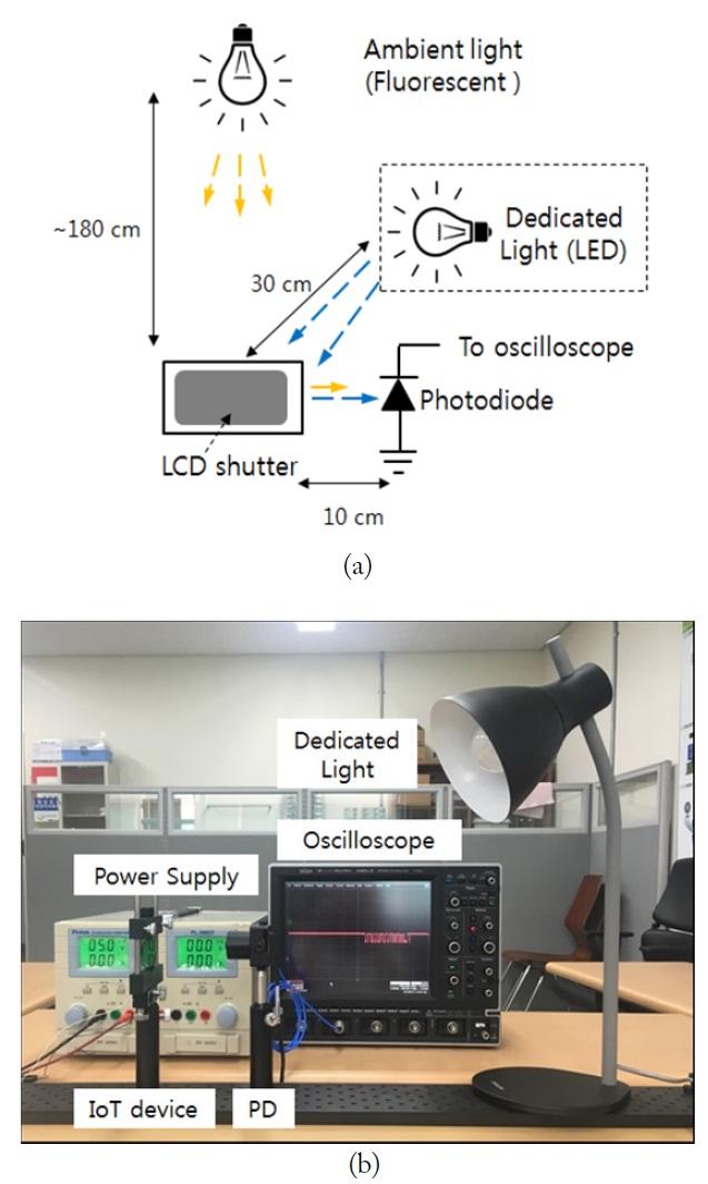
Fig. 3 illustrates the experimental setup of our proposed ambient light backscatter communication design in a typical office environment, where ambient light is maintained at a comfortable range of around 300 lx. To investigate the effect of the illumination source, we also conducted additional experiments with a dedicated LED lighting source.
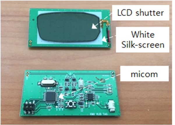
The experimental setup comprised an IoT device and a PD receiver module. The distance between the IoT device and the PD receiver is fixed at 10 cm. We fabricated an IoT device consisting of a self-designed PCB and an LCD shutter, as shown in the photograph in Fig. 4. We attached an LCD shutter, which was originally used in 3D TV glasses (SSG-5150GB, Samsung), to the front of the PCB to modulate the ambient visible light. The microcontroller (ATmega128) transmitted 64 bit random data to the LCD shutter. To drive the LCD shutter, the data were converted to the proper voltage level, which modulated the LCD shutter. If the driving voltage of the LCD shutter was above 5 V (ON), the LCD shutter would become opaque (with a transmittance of 2%). If the voltage was below 2 V (OFF), the LCD shutter would become transparent (with a transmittance of 34%). This selective switching of the LCD shutter enabled the IoT device to send its own information. Finally, the backscattered signal was detected by a wide bandwidth optical receiver (PDA36A, Thorlabs), which was displayed on a generalpurpose oscilloscope. The PDA36A can detect light signals over a 350−1,100 nm wavelength range.
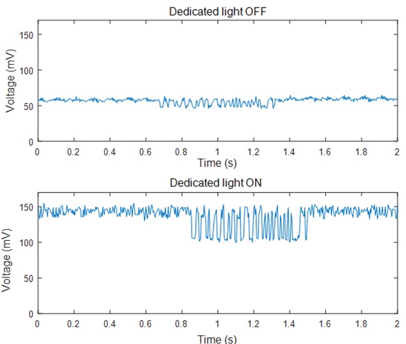
Fig. 5 shows the experimental results of our demo system. Using only ambient fluorescent lighting as the lighting source, which was installed on the ceiling at a height of 180 cm, the backscattered signal from the LCD shutter was successfully decoded using a low-cost PD module. For comparison, we also used a dedicated LED light as an additional light source at a distance of 30 cm from the LCD shutter. When the LED was ON, the backscattered signal was three times greater than when the dedicated light was not used. Naturally, light energy could be added without any interference.
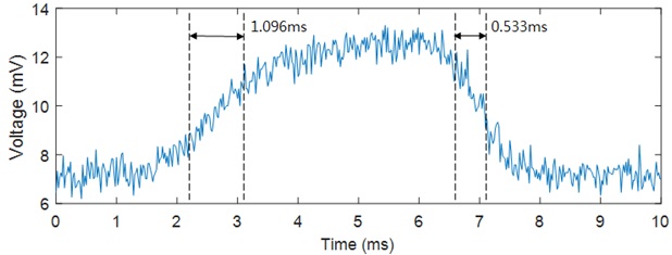
Fig. 6 presents the measured optical response of the LCD shutter using a PDA36A. When driven by a voltage source with a 5-ms pulse width, the LCD shutter response is similar to that of a low pass filter response and can thus be modeled as a first-order resistor−capacitor circuit. We measured the rising time
In this paper, we proposed a design for using ambient light backscatter communication in IoT applications. The IoT device could send its information by selectively switching an LCD shutter, which is located on the device surface. We conducted experiments to confirm the feasibility of this design and successfully demonstrated the performance of 100 bps communication over a distance of 10 cm without any dedicated lighting source. We believe that our proposed ambient light backscatter communication paves the way for innovation in future IoT applications by facilitating easy user interaction.