Recently, as interest in the civil radar industry has increased, various studies relating to the general use of radar technology have been undertaken. Research on low-power and near-distance measuring radar while using the industrial, scientific, and medical (ISM) band-the frequency of which can be used without government permission-has generally increased, and there have been efforts to adapt this radar to software-defined radar (SDR) platforms. In general, microstrip patch antennas-which are conventional S-band SDR antennas-are preferred, owing to their high-volume efficiency.
However, their drawbacks are high power loss in transmission and a tendency to distort radiation patterns; these derive from their indispensable feeding structures. On the other hand, horn/waveguide-type antennas can handle high-power and high-gain conditions, but are large and heavy, resulting in space-allocation difficulties for system integration [1, 2]. The results of this study suggest that, considering their low distortion, low power loss, light weight, and high-volume efficiency, the use of novel substrate integrated waveguide (SIW)-based antennas is preferable to that of conventional microstrip and horn/waveguide-type antennas; the former of these have been proposed and analyzed in several configurations. SIW-based transmission lines can be materialized in common printed circuit boards (PCBs) and have the same operating principles as metallic rectangular waveguides [3, 4]. As a basic characteristic of standard waveguides, the dominant mode of SIW transmission lines is TE10 [1].
Moreover, interference with other devices can be minimized if the feeding part is materialized by SIW transmission lines [1]. Especially, the isolation characteristic is a key factor for SDR antennas, because transmitting and receiving antennas are placed in an adjacent location-and, in the case of applying the SIW transmission line structure, interference between the transmitting and receiving antennas can be considerably reduced.
Furthermore, this study addresses the meander-line structure, which is used to miniaturize the conventional ring-slotted SIW antenna and reduce its size by about 23%. To obtain return losses less than -15 dB and -20 dB, respectively, the optimal parameter values of an effective equivalent via radius and via gap widths were selected only under the operation of the TE10 mode propagating inside and without any higher-order modes. The proposed antennas are designed on RT/Duroid 5880 PCB; the thickness and relative permittivity of the board are 1.57 mm and 2.2 mm, respectively. In Section II, the relationships between the design parameters and antenna performance for both SIW-based antennas are described by simulation, using commercially available full electromagnetic software. Section III discusses the measurement results vis-à-vis the designed antennas and radar cross-section (RCS) detection radar experiments through the SDR platform; this is followed by a brief conclusion in Section IV.
II. SIW-BASED ANTENNA GEOMETRY AND DESIGN PROCEDURE
1. SIW-Based Ring-Slotted Antenna
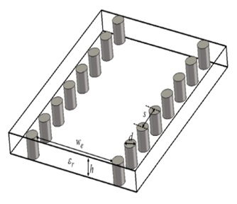
Rather than a conventional microstrip patch antenna, an SIW structure-the use of which leads to reduced fringing loss and distortion otherwise caused by higher-order modes-is proposed, which uses metallic via arrays (Fig. 1).
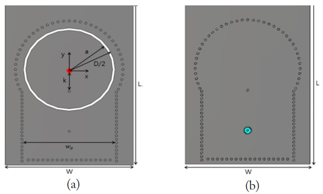
In the SIW-based ring-slotted antenna, the shorting via that connects the conductor plate inside a slot in the bottom plate performs an especially important role in matching antenna impedance and generating the required resonant frequency [1]. From the results of rigorous parametric studies, we know that a circularly polarized wave can be created through the installation of a shorting via at an asymmetric position [3, 4]. At this time, the shorting via is positioned on the y-axis to intentionally and simply generate the linearly polarized wave needed for SDR applications.
In Fig. 2,
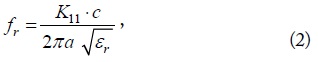
where
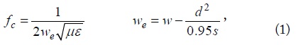
The plan for the antenna proposed in this study was that it would be used at 2.4–2.4835 GHz of the ISM standard, and at a channel bandwidth of 35 MHz (center frequency = 2.433 GHz). To satisfy the operating frequency band (2.415–2.45 GHz), the via radius and via gap are optimally selected and the cutoff frequency of the SIW structure is set at around 1.8 GHz. The effective equivalent width

where
However, in designing the antenna, Eq. (2) provides only rough boundaries for the design parameters; rigorous parametric study is needed to decide the optimal design parameters. The optimal values were found to be as follows: radius of the inner slot
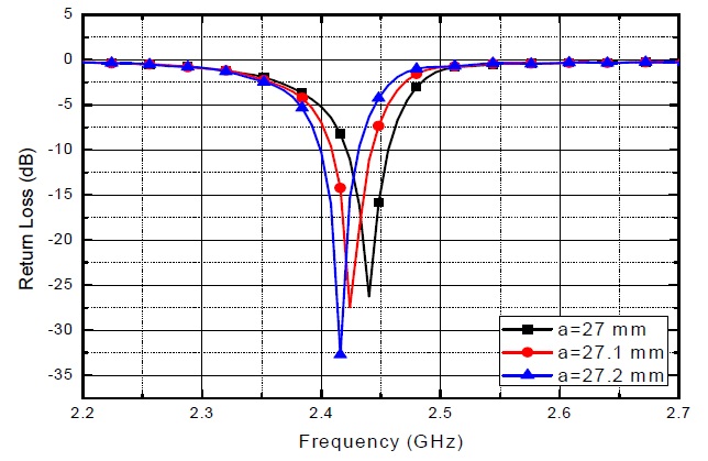
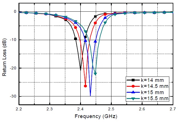
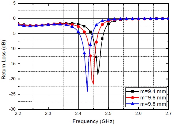
The resonant frequency sensitively depends on the radius of the circular patch. As the radius increases, the resonant frequency is expected to decrease. It is clear that the position of the shorting via is another critical design factor for the SIW-based ring-slotted antenna.
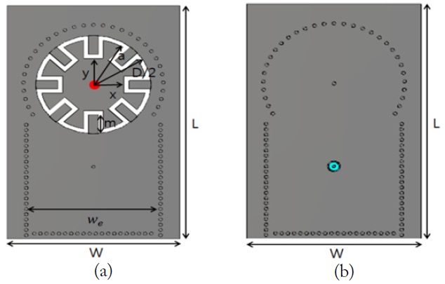
2. SIW-Based Meandered-Slot Antenna
The previously designed SIW-based ring-slotted antenna in Fig. 2 has a total size of 112 mm × 80 mm (
Additionally, the optimized outer slot diameter
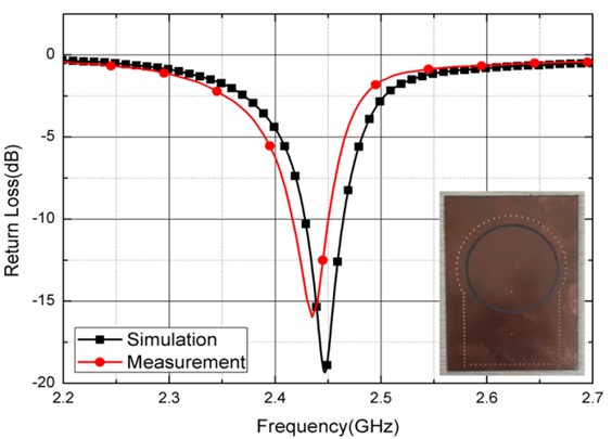
First, the return loss characteristics of the simulated and manufactured SIW-based ring-slotted antenna were investigated (Fig. 7). The bandwidth of the simulated antenna under the criterion of less than -10 dB ranged from 2.43 to 2.465 GHz; the required channel bandwidth was 35 MHz. In addition, the bandwidth of the manufactured antenna under the criterion of less than -10 dB ranged from 2.415 to 2.45 GHz, and the channel bandwidth was almost identical to the simulation result.
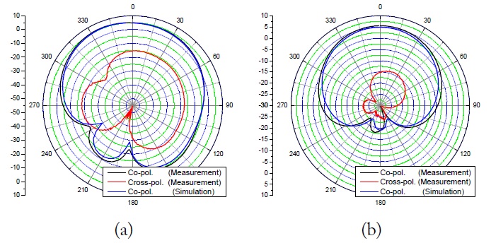
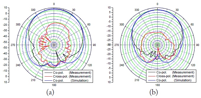
We checked the linear polarization (LP) properties needed to develop SDR platforms; Fig. 8 shows the Co-pol. and X-pol. characteristics of the given Model 1 antenna.
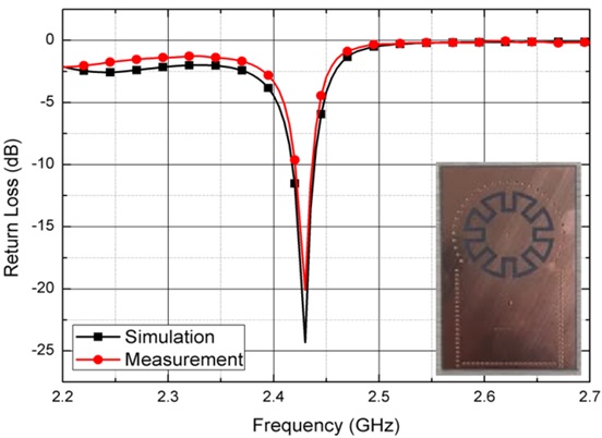
As shown in Fig. 8(a) and (b), the antenna gain exceeds 8 dBi at 2.435 GHz, and the half-power beam width (HPBW) is 78°, which is a wide beam width. It is noted that the Co-pol. and X-pol. at the bore sight of the antenna correspond to the V-pol. and H-pol., respectively, and that the difference between the Co-pol. and X-pol. is -23 dB and -25 dB, respectively. This therefore indicates that the proposed antenna has high-purity linear polarization properties. In terms of return losses, the results of the measured and simulated antenna strongly align. Figs. 9 and 10 delineate the return loss property and the measured radiation pattern of the SIW-based meandered-slot antenna, respectively.
Like the SIW-based ring-slotted antenna (Model 1), the Co-pol. and X-pol. of the meandered-slot antenna (Model 2) are both measured to determine their linear polarization properties. The bandwidth of the simulated antenna was 2.4165–2.4435 GHz, and the required channel bandwidth was 27 MHz. Additionally the bandwidth of the manufactured antenna was 2.4175–2.4425 GHz, and the center frequency was identical to the simulation result. Fig. 10 shows the radiation pattern, and that the gain of the meandered-slot antenna exceeds 5 dBi at 2.43 GHz and the HPBW was 87°, thus indicating a wide beam width.
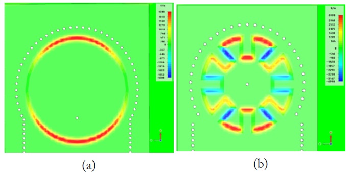
With regards to LP purity, the results show that the meandered-slot antenna also has a high-purity linear polarization property. Moreover, the LP property of both antennas could be verified through the use of animated field distributions (Fig. 11).
2. RCS Detection Radar Experiment
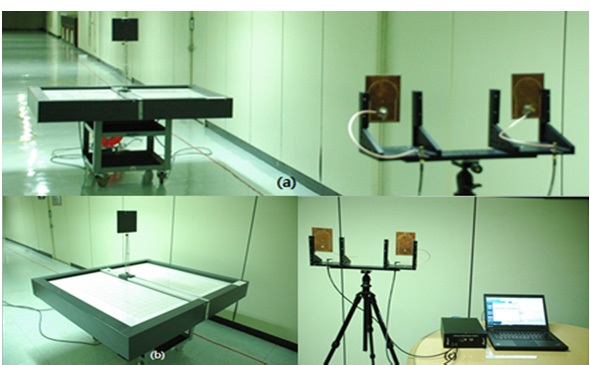
In this study, to determine the maximum distance at which a moving target could be detected by the antenna, detection was confirmed by changing the distance between stages. The detection experiment was performed inside a building, in a real-world application. The metal plate-which has 1 m2 of RCS-was set to move toward the bore-sight direction of the antenna. A moving target with a constant RCS and constant velocity can be identified through signal analysis of the returned Doppler frequency.
Fig. 12 illustrates the test environment of the RCS detection experiment. The experiment was carried out under several conditions, at 10–30 m from the antenna surface.
The moving velocity of the RCS was set to be 0.3 m/s, and the Doppler frequency that corresponds to the moving target was found to be 5 Hz. Experiments for other cases were executed to validate our systems.
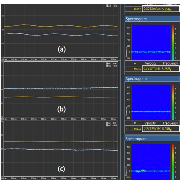
Fig. 13 shows the detection results as per the SDR software, depending on target distance. The amplitude of the signal decreases as the distance increases, but the detected velocity and Doppler frequency have constant values of 0.321 m/s and 5.25 Hz, respectively. These values correspond to the initial setup velocity of 0.3 m/s and the expected Doppler frequency of 5 Hz.
Therefore, according to the experimental results, the antenna proposed and described in this paper can detect the motion of a target that is 30 m from the antenna.
This paper proposes, and describes the design of, an S-band radar antenna mounted on an SDR platform. Since an SDR antenna requires a high-isolation characteristic, the SIW structure was applied and the antenna design parameters were optimized and determined throughout this repetitive parametric study. Moreover, in an RCS detection experiment using an SDR platform, the velocity and Doppler frequency of the RCS at a distance of 30 m from the antenna were detected. It was shown that the proposed SIW-based slotted antenna is a good and appropriate candidate for indoor motion detection.

![Substrate integrated waveguide transmission line [1].](http://oak.go.kr/repository/journal/20450/E1ELAT_2016_v16n4_248_f001.jpg)