검색 전체 메뉴
PDF
맨 위로
OA 학술지
An Eight-Element Compact Low-Profile Planar MIMO Antenna Using LC Resonance with High Isolation
  • 비영리 CC BY-NC
  • 비영리 CC BY-NC
ABSTRACT
An Eight-Element Compact Low-Profile Planar MIMO Antenna Using LC Resonance with High Isolation
KEYWORD
Isolation Technology , MIMO , Mutual Coupling
  • I. INTRODUCTION

    In multi-path environments, a high channel capacity is required in order to send more data in the desired direction. A multi-input multi-output (MIMO) antenna exploits multiple antenna elements to achieve a higher channel capacity that is proportionate to the number of antenna elements [1]. The conventional approach for MIMO applications is to arrange the antennas over more than half of the wavelength to avoid correlation [2]; thus, it extends the physical size of the antenna. Moreover, increasing the number of antenna elements in a mobile device affects MIMO performance due to mutual coupling between antennas.

    Several MIMO antenna designs have been proposed to minimize the mutual coupling between antenna elements and to simultaneously decrease the antenna size. The basic approach is to increase the space between antennas, but the space is limited, especially for mobile applications. Decoupling networks [3, 4], the slit pattern [5], the parasitic element [6], and the electromagnetic band gap (EBG) [7, 8] have been analyzed; however, these methods require additional space on an antenna. In this paper, we propose a compact low-profile planar MIMO antenna that unites eight inverted-F antennas with an isolationenhanced structure. We designed the proposed antenna to achieve high isolation between the antenna elements and we verified the antenna's function by identifying the surface current and radiation patterns.

    II. DESIGN OF THE PROPOSED ANTENNA

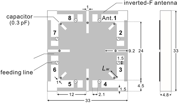
    The antenna shown in Fig. 1 was designed by expanding the isolation-enhanced structure with the slot and capacitor, as described in [9]. The proposed antenna is fabricated on an FR4 substrate; the size of the antenna is 33 mm× 33 mm, which is smaller than the conventional λ/2 MIMO antenna. An inverted-F antenna is flipped and rotated along the ground, forming eight antenna elements. All the antenna elements are arranged by considering an antenna radiation pattern and are the same size, with matching at 5 GHz. Better impedance matching can be achieved by adjusting the length of the upper arm or the distance between the feeding line and the shorting line. All of the antenna patterns with capacitors are inscribed on the top layer. Three FR4 1.6t substrates are stacked to reduce the electrical size per unit antenna element to decrease the size. The isolation-enhanced structure is placed between the two inverted-F antenna elements that are facing each other. Although the distance between two adjacent antenna elements is λ/30, closer than in [10], the proposed antenna can achieve 30-dB isolation using LC resonance with high isolation.

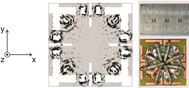
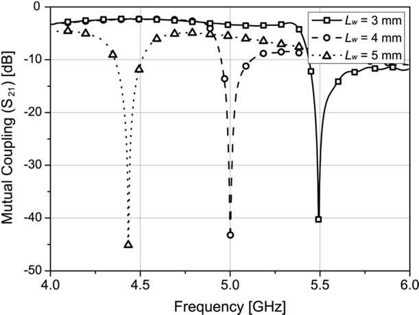
    The 5-GHz surface current of the proposed antenna is depicted in Fig. 2. A slot and capacitor pair is located between two antenna elements. As the slot can be regarded as an inductor, the inductor with a 0.3-pF capacitor causes LC resonance. The resonant frequency of the LC resonance decreases when the slot length located on the four corners (Lw) increases, as in Fig. 3, where Lw = 4 mm is chosen as the proposed antenna. If the resonant frequency of the LC resonance matches with the operating frequency of the inverted-F antenna element, the slot and capacitor separate the ground between the two antenna elements. The surface current along the ground is confined to the LC resonance, which then disturbs the mutual coupling between the two antenna elements. The effect of the isolation-enhanced structure is stronger when the directions of the two antenna elements are crossed. The use of the slot and capacitor ensures high isolation even when the two radiation patterns overlap, e.g. ports 1 and 2, which can result in high coupling between the ports of the antenna.

    III. SIMULATED AND MEASURED RESULTS

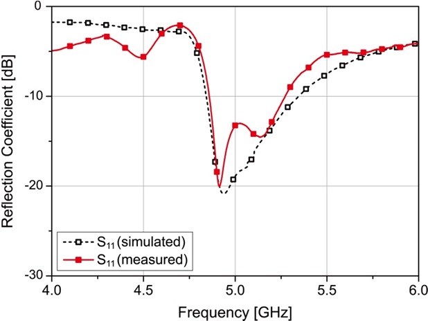
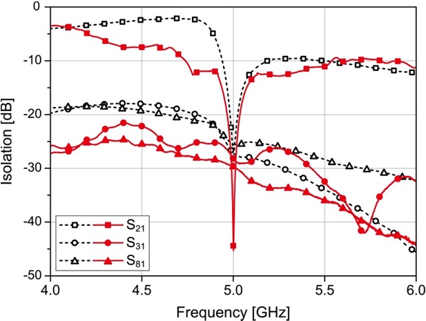
    The return loss and isolation of the proposed antenna are measured with an Agilent 8722ES network analyzer in the measurement range of 4 - 6 GHz. The S-parameter between the antenna elements was obtained from the cable that connects each feeding point of the inverted-F antenna to the connector and the other ports were terminated with 50-Ω termination loads. The simulated and measured reflection coefficients of antenna element 1 are shown in Fig. 4; there was good agreement between the simulated and measured responses. The measured −10 dB impedance bandwidth (S11) is 4.86 - 5.27 GHz, and the reflection coefficients of each antenna element are roughly similar since all the antenna elements are identical. Fig. 5 depicts the simulated and measured isolations from antenna element 1 to the neighboring antenna elements. The measured results reveal that the isolation-enhanced structure in the proposed antenna ensures approximately 30-dB isolation at 5 GHz (fc) between antenna elements.

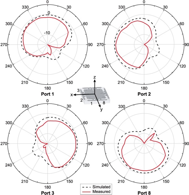
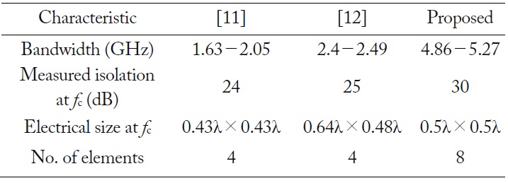
    Fig. 6 shows the simulated and measured radiation patterns at 5 GHz for ports 1, 2, 3, and 8 in the proposed antenna. The radiation patterns of the inverted-F antennas that radiate in the electrical field are determined by the direction of the upper arm. The radiation patterns of the antenna elements differ from each other. As can be seen, the radiation patterns of adjacent antenna elements are dissimilar enough to radiate individually with a peak gain of −1.65 dBi. Th erefore, it is inferred that the proposed antenna has eight different radiation patterns. Table 1 summarizes the specifications of the multi-port compact MIMO antenna and it also shows the number of integrated antenna elements compared with other previous works. The proposed antenna has attractive features such as approximately 30-dB isolation using LC resonance and wide coverage on the azimuth plane using eight antenna elements.

    [Table 1.] Comparison between compact MIMO antennas

    label

    Comparison between compact MIMO antennas

    IV. CONCLUSION

    In this paper, we propose a compact low-profile MIMO antenna that integrates multiple antenna elements with an isolation-enhanced structure employing a slot and capacitor for small mobile applications. Our experimental results verify the feasibility of the design incorporating eight antenna elements in a very small area. The proposed antenna is easy to implement within a planar structure and has a high isolation characteristic with a simple slot and capacitor structure. The proposed antenna can be utilized to transfer data with high channel capacity within the operating frequency band.

참고문헌
  • 1. Sharawi M. S. 2013 "Printed multi-band MIMO antenna systems and their performance metrics [wireless corner]," [IEEE Antennas and Propagation Magazine] Vol.55 P.218-232 google cross ref
  • 2. Pozar D. M., Schaubert D. H. 1995 Microstrip Antennas: The Analysis and Design of Microstrip Antennas and Arrays. google
  • 3. Chen S. C., Wang Y. S., Chung S. J. 2008 "A decoupling technique for increasing the port isolation between two strongly coupled antennas," [IEEE Transactions on Antennas and Propagation] Vol.56 P.3650-3658 google cross ref
  • 4. Han M. S., Choi J. 2009 "MIMO antenna using a decoupling network for next generation mobile application," [in Proceedings of the 9th International Symposium on Communications and Information Technology] P.568-571 google
  • 5. Chiu C. Y., Cheng C. H., Murch R. D., Rowell C. R. 2007 "Reduction of mutual coupling between closely-packed antenna elements," [IEEE Transactions on Antennas and Propagation] Vol.55 P.1732-1738 google cross ref
  • 6. Min K. S., Kim D. J., Moon Y. M. 2005 "Improved MIMO antenna by mutual coupling suppression between elements," [in Proceedings of the European Conference on Wireless Technology] P.135-138 google
  • 7. Yang L., Fan M., Chen F., She J., Feng Z. 2005 "A novel compact electromagnetic-bandgap (EBG) structure and its applications for microwave circuits," [IEEE Transactions on Microwave Theory and Techniques] Vol.53 P.183-190 google cross ref
  • 8. Islam M. T., Alam M. S. 2013 "Compact EBG structure for alleviating mutual coupling between patch antenna array elements," [Progress in Electromagnetics Research] Vol.137 P.425-438 google cross ref
  • 9. Park J., Choi J., Park J. Y., Kim Y. S. 2012 "Study of a Tshaped slot with a capacitor for high isolation between MIMO antennas," [IEEE Antennas and Wireless Propagation Letters] Vol.11 P.1541-1544 google cross ref
  • 10. Mak A. C. K., Rowell C. R., Murch R. D. 2008 “Isolation enhancement between two closely packed antennas,” [IEEE Transactions on Antennas and Propagation] Vol.56 P.3411-3419 google cross ref
  • 11. Zhang S., Zetterberg P., He S. 2010 "Printed MIMO antenna system of four closely-spaced elements with large bandwidth and high isolation," [Electronics Letters] Vol.46 P.1052-1053 google cross ref
  • 12. Li H., Xiong J., Ying Z., He S. 2010 "High isolation compact four-port MIMO antenna systems with built-in filters as isolation structure," [in Proceedings of the Fourth European Conference on Antennas and Propagation] P.1-4 google
OAK XML 통계
이미지 / 테이블
  • [ Fig. 1. ]  Geometry and dimensions of the proposed eight-element MIMO antenna (units: mm).
    Geometry and dimensions of the proposed eight-element MIMO antenna (units: mm).
  • [ Fig. 2. ]  Surface current distribution and prototype for the proposed antenna.
    Surface current distribution and prototype for the proposed antenna.
  • [ Fig. 3. ]  Comparison of the simulated mutual coupling according to the slot lengths.
    Comparison of the simulated mutual coupling according to the slot lengths.
  • [ Fig. 4. ]  Simulated and measured reflection coefficients of antenna element 1.
    Simulated and measured reflection coefficients of antenna element 1.
  • [ Fig. 5. ]  Simulated and measured isolations between other antennas (ports 2, 3, and 8) and antenna 1 (port 1). The dotted black and solid red lines are the simulated and measured results, respectively.
    Simulated and measured isolations between other antennas (ports 2, 3, and 8) and antenna 1 (port 1). The dotted black and solid red lines are the simulated and measured results, respectively.
  • [ Fig. 6. ]  Simulated and measured radiation patterns in the XY plane at 5 GHz.
    Simulated and measured radiation patterns in the XY plane at 5 GHz.
  • [ Table 1. ]  Comparison between compact MIMO antennas
    Comparison between compact MIMO antennas
(우)06579 서울시 서초구 반포대로 201(반포동)
Tel. 02-537-6389 | Fax. 02-590-0571 | 문의 : oak2014@korea.kr
Copyright(c) National Library of Korea. All rights reserved.